Abstract
To explore the optimal design method for main support structure of micro satellite, this paper proposed a method targeting the random acceleration response RMS value of the space camera installation position when design the main support structure of LQ-video satellite in Jilin-1 group satellites. Camera main support structure optimization mathematical model was established, and the thickness and flexible beam position of the flexible beam support structure has been optimized in the establishment of the optimization mathematical model. When the flexible beam thickness is 2.5 mm, and the distance between it and the support structure mounting surface is 94.5 mm, the camera installation point acceleration response root mean square (RMS) value is minimal. Engineering analysis showed that the maximal random response RMS of the camera installation point is 19.6 grms and the maximal relative magnification is 0.93. The camera mechanics test showed that the maximal relative error of finite element analysis and experimental measurements is 4.0 % and the maximal relative magnification of the response is 1.2 which is less than the overall index 1.5. It proved that the optimization method is effective and feasible.
1. Introduction
Modern micro-satellite has a strong practicability for small size, light weight, low cost, short development cycle and high performance characteristics [1, 2]. Therefore, the micro satellite has been paid more attention in the field of international space technology. With the vigorous development of micro satellite, the effective load ratio is increasing, and the requirements of the main structure of the satellite are more severe [3-5]. Exploring optimization method is even more urgent for main structure design of micro satellite.
LQ-video satellite in Jilin-1 group satellites is a micro video imaging satellite whose mass is no more than 95 Kg. Aiming at reducing the satellite structure mass and volume, it uses space-borne integration design to improve the structure density of micro satellite. The camera is connected with the satellite through the camera main support structure. When the rocket launches, the satellite suffering random acceleration vibration excitation which is integrated by pulsation generation rocket thrust, jet noise and turbulent boundary layer noise [6-8]. If the acceleration vibration directly passed through the main support structure to the camera, it will cause the camera structural deformation or even destroyed. Therefore, the camera main support structure should be optimized to gain a better dynamic performance under a given frequency band.
The existing research, based on random vibration theory and test, mostly examined the structural strength of the satellite rather than optimized the structure of the dynamic parameters [9-12].For instances, W. Jung, A. P. Mazzoleni, J. Chung [13] presents a dynamic analysis of a tethered satellite system with a moving mass.The analysis results show that a one-piece dumbbell model is qualitatively valid for studying the system under certain conditions, such as when the initial liberation angles, moving mass velocity, and moving mass size are small, the tether length is large, and the mass ratio of the two satellites is large. You B., Zhang H., Li W., et al. [14] presented a methodology for modeling and analysis of satellite antenna systems considering the effects of the joint clearance and reflector flexibility in the system. Based on a thorough geometric description of the eccentricity vector, the multibody dynamics of satellite antenna are analyzed by considering a flexible reflector with ideal and nonideal joints.
According to LQ-video satellite overall design requirements, this paper proposed a method to optimize design camera main support structure targeting the random vibration response RMS value of the camera installation position, and established a random vibration response optimization model. The thickness of the flexible joint and flexible beam position has been optimized. In order to verify the optimization results, engineering analysis and mechanical testing of the optimized camera main support structure are carried out. The results showed that the optimization designed main support structure match the overall satellite design specifications well, and the optimize design method is effective and feasible.
2. Optimization model
Size optimization is one of the most important topology optimization method, especially used in structure optimization [15-17]. It refers to a mathematical method for optimizing material distribution in a given area under a given load conditions, constraints and performance indicators. The optimization mathematical is established from the objective function, design variables and constraint conditions, and the optimization process is explained in this section.
2.1. Systematic random response function
Spectrum analysis method is generally used in the random response. An n degrees’ freedom linear system is expressed by random excitation and its kinetic equation [18, 19] is represented as Eq. (1):
where, , and respectively represent -order mass matrix, damping matrix and stiffness matrix. is displacement vector, is velocity vector, is acceleration vector and is system incentives.
Assume the acceleration incentive is , and its power spectral density (PSD) is , the kinetic random vibration equation is represented as Eq. (2):
where, indicates an acceleration vector.
First, to solve system’s intrinsic mode, it should be , and the system free motion equation [20] is represented as Eq. (3):
The corresponding characteristic equation is represented as Eq. (4):
System -degree natural frequency is , and the corresponding mode of vibration is , 1, 2,…, . where, , , , the mode of vibration multiplies a constant multiplier and the mass normalized vibration mode is . In classical damping, the Eq. (2) rewrite as follows:
In this formula, is the system -th modal damping ratio; is the -th mode participation coefficient:
Relationship between and is:
Solution of Eq. (5) in the time domains is:
where, is the -th impulse response function.
Through Eqs. (7)-(8), we get:
The auto correlation function of the matrix is:
According to the Wiener-Khintchine relationship [21], output PSD is the Fourier transform of the output of autocorrelation function. By exchanging integral order, and introducing variable , we get output PSD function as follows:
Input PSD function is the Fourier transform of input auto correlation function , and frequency transfer function is the Fourier transform of impulse response function , then Eq. (11) rewrite as Eq. (12):
Generally, ignoring the cross-order terms to simplify approximation method is used in engineering in Eq. (12), the response PSD abbreviated as follows:
The random acceleration RMS response expression which is also the optimization objective function shown in Eq. (14):
2.2. System sensitivity
Modal analysis is used to determine the vibration characteristics of the structure. It is mainly about the natural frequency and vibration mode of the system structure, which is an important index to investigate the dynamic stiffness. Structural low order mode is also an important basis for modifying the structure. The modal sensitivity of the structure is analyzed as follows.
and are the -th isolated eigen values and the corresponding mode vectors, which satisfy the characteristic Eq. (15):
and are the derivative of and under the design variable (1, 2,…, ), and are the derivative matrix of and under the design variable . Eigen values sensitivity and modal vector sensitivity are as follow:
To calculate and it should be calculate and first. In this paper, shell thickness is used in the optimization analysis. Therefore, the derivative matrix of the shell element matrix and the derivative matrix of the mass matrix are given.
Derivative Eq. (14), we would get random acceleration response sensitivity.
2.3. Design variables
Support structure flexible beam thickness and distance from flexible beam to support structure mounting surface are written as Eq. (20):
where, is thickness of flexible joint, is distance from flexible beam to support structure mounting surface.
2.4. Mathematical model
LQ-video satellite requires that the primary frequency of the camera main support structure is greater than the camera primary frequency 110 Hz. The safety factor is 1.2, the primary frequency of the camera main support structure is no less than 132 Hz. The and satisfy the Eq. (21):
where, represents the thickness variable, represents the distance variable.
The camera main support structure size optimization mathematical model is expressed as Eq. (22):
Until now, the random vibration mean square response is converted into a deterministic harmonic response analysis problem based on the virtual excitation method, and the sensitivity of the modal sensitivity and random acceleration response are analyzed.
3. Optimization process and results
According to the mathematical model in Section 2, the sizing optimization was introduced to optimize the thickness of the flex joint and the flex joint position in the main support structure of the camera. The optimization design flow is shown in Fig. 1.
Fig. 1Flow chart
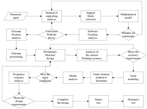
Table 1The acceleration power spectrum (PSD)
Frequency (Hz) | Power spectral density |
20-150 | +3 dB/oct |
150-280 | 0.08 g2/Hz |
280-320 | 0.30 g2/Hz |
320-380 | 0.20 g2/Hz |
380-850 | 0.10 g2/Hz |
850-1000 | 0.04 g2/Hz |
1000-2000 | 0.01 g2/Hz |
Overall design of the LQ-video satellite requires that the height of main support structure of the camera is 118 mm. The material of the main supporting structure is Titanium alloy TC4 which is provided with low density and high strength.
The applied loads are the random acceleration which is from the rocket in launching. The acceleration power spectrum is shown in Table 1, and the RMS value of PSD is 10.16 g. Structural damping is 0.03 in this model.
Optimize step size is 0.5 mm during the optimization design process. After 69 steps of iteration, the random vibration acceleration response of the camera mounting point is minimal and thickness of flexible joint is 2.5 mm, distance is 94.5 mm. Optimization iterative process convergence curve is shown in Fig. 2.
4. Finite element numerical analysis
To estimate the optimization result, the finite element analysis is carried out by using MSC. Patran&Nastran 2013. FEM includes secondary mirror (SM), SM linker, SM substrate, SM light shield, SM support, Primary mirror (PM), PM substrate, base plate and camera support structure which contains 56614 nodes, 35532 elements, 12 RBE2 and 1 CONM2. FEM is shown in Fig. 3.
Fig. 2Iterative convergence curve
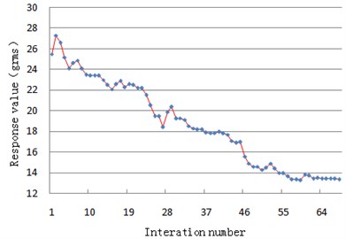
Fig. 3Finite element model
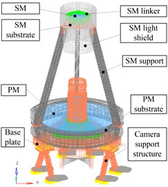
Table 2Main materials parameters
Name | Material | Elastic modulus (MPa) | Nu | Density (kg/m3) |
SM | Zerodur | 91 | 0.24 | 2500 |
PM | ||||
SM linker | Titanium alloy (TC4) | 110 | 0.34 | 4400 |
SM support | ||||
SM substrate | ||||
Base plate | ||||
Camera support structure | ||||
SM light shield | M40 | 70 | 0.3 | 1500 |
PM substrate | T700 | 50 | 0.28 | 1800 |
Table 3FE analysis results
Order | Frequency (Hz) | Modal formation |
1 | 141.8 | Support structure swing along axis |
2 | 156.4 | Support structure swing along axis |
3 | 320.7 | Support structure rotation around the axis |
Direction | Input RMS (g) | Output response RMS of sample point (g) |
-axis | 10.16 | 15.2 |
-axis | 19.8 | |
-axis | 23.3 |
5. Experiments
To verify the feasibility of the size optimization method and the accuracy of the finite element numerical analysis results, we used the model vibration test bench (# MPA3436/H1859A) to test the camera at room temperature according to conditions in Table 1. Test scene is shown in Fig. 4.
Curves of input, analysis and test of the random vibration response of the camera main support structure in the -axis, -axis and -axis are shown in Fig. 5. The comparison of random vibration response test results and the analytical data are listed in Table 4.
Fig. 4Placement of random vibration test
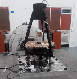
Fig. 5Curves of input, analysis and test
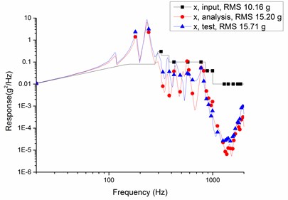
a) axis
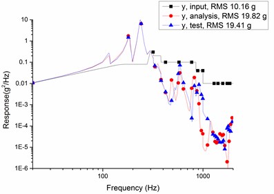
b) axis
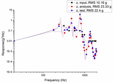
c) axis
Table 4Compare data of tests and analysis (grms)
Axis | Input | Analysis result | Test result | Relative errors | Relative magnification |
10.16 | 15.2 | 15.7 | 3.8 % | 0.54 | |
10.16 | 19.8 | 19.4 | 2.1 % | 0.91 | |
10.16 | 23.3 | 22.4 | 4.0 % | 1.2 |
According to Table 4, the relative errors of random vibration response between finite element analysis results and vibration test data are less than 5 %, and the maximum relative magnification is 1.2 which is less than overall index 1.5. The results validate correctness of finite element models and feasibility of optimization methods in this paper.
6. Conclusions
Traditional optimization methods are mostly based on static mechanical properties parameters or frequency characteristics, which cannot directly optimize the dynamic parameters of the structure. In this paper, due to the RMS value of the acceleration response of the main support structure of the LQ-video satellite in Jilin-1 group satellites is too large under the random vibration excitation, the optimization design method based on the RMS value of the random response is proposed, and the following conclusions are got.
1) The mathematical model of random vibration response optimization is established, the modal and acceleration response sensitivity analysis of the model are carried out, and the optimal design of the main support structure is also provided. This method can provide a new idea for the design of other small satellite main structure.
2) The thickness of the main support structure of the camera is 2.5 mm and the distance between the support structure and mounting surface is 94.5 mm after size optimization, the random vibration acceleration response of the camera mounting position is minimum.
3) Engineering analysis and test results show that the main support structure of the camera is 141.8 Hz, which is larger than the overall index 110 Hz, and the maximal relative amplification rate of the support structure is 1.2, which is less than the overall design index 1.5. The main support structure of the camera performance parameters match the overall index well.
References
-
Yatsu Y., Hayashi M., Kawakami K., et al. Development of a micro-satellite TSUBAME for X-ray polarimetry of GRBs. Proceedings of the International Astronomical Union, Vol. 7, Issue 279, 2015, p. 423-424.
-
Underwood C., Pellegrino S., Lappas V. J., et al. Using cubesat/micro-satellite technology to demonstrate the autonomous assembly of a reconfigurable space telescope (AAReST). Acta Astronautica, Vol. 114, 2015, p. 112-122.
-
Triharjanto R. H., Poetro R. E., Hardhienata S. Multi-objectives optimization of earth observation micro-satellite design using particle swarm. IEEE International Conference on Aerospace Electronics and Remote Sensing Technology, 2014, p. 192-196.
-
Safarabadi M., Bazargan S. Prediction of equivalent static loads act on a micro satellite via modal analysis. Engineering Solid Mechanics, Vol. 3, Issue 2, 2015, p. 75-84.
-
Romero S., Smitz J. Integrated design technique of satellite platform and payload based on micro-vibration isolators. Spacecraft Recovery and Remote Sensing, Vol. 137, Issue 6, 2014, p. 997-1005.
-
Dziopa Z., Koruba Z. The impact of launcher turret vibrations control on the rocket launch. Bulletin of the Polish Academy of Sciences Technical Sciences, Vol. 63, Issue 3, 2015, p. 717-728.
-
Bertin J., Batson J. L. Comparison of cold-gas simulations and rocket-launch data for constrictive launchers. Journal of Spacecraft and Rockets, Vol. 13, Issue 11, 2015, p. 684-691.
-
Thirty Meter Telescope Detailed Science Case: 2015 Warren Skidmore on behalf of the TMT International Science Development Teams and TMT Science Advisory Committee. Research in Astronomy and Astrophysics, Vol. 12, 2015, p. 1945-2140.
-
Xiong H., Kong X., Yang Zh., Liu Y. Response regimes of narrow-band stochastic excited linear oscillator coupled to nonlinear energy sink. Chinese Journal of Aeronautics, Vol. 2, 2015, p. 457-468.
-
Bendsoe M. P., Sigmund O. Topology Optimization: Theory, Methods and Applications. Berlin, Springer, 2003, p. 9-69.
-
Lu S. An overview of a unified theory of dynamics of vehicle-pavement interaction under moving and stochastic load. Journal of Modern Transportation, Vol. 3, 2013, p. 135-162.
-
Tang Ch., Zhang Y., Zhao G., Ma Y. Annoyance rate evaluation method on ride comfort of vehicle suspension system. Chinese Journal of Mechanical Engineering, Vol. 2, 2014, p. 296-303.
-
Jung W., Mazzoleni A. P., Chung J. Dynamic analysis of a tethered satellite system with a moving mass. Nonlinear Dynamics, Vol. 75, Issues 1-2, 2014, p. 267-281.
-
You B., Zhang H., Li W., et al. Dynamic analysis of satellite antenna system with joint clearance and reflector flexibility. Journal of Aerospace Engineering, Vol. 27, Issue 2, 2014, p. 297-307.
-
Bendsoe M. P., Kijuchi N. Generating optical topologies in structural design using a homogenization method. Computer Methods in Applied Mechanics and Engineering, Vol. 71, Issue 2, 1988, p. 193-202.
-
Cho J. G., Koo J. S., Jung H. S. A lightweight design approach for an EMU carbody using a material selection method and size optimization. Journal of Mechanical Science and Technology, Vol. 30, Issue 2, 2016, p. 673-681.
-
Tomsia P., Duhovnik J. Simultaneous topology and size optimization of 2D and 3D trusses using evolutionary structural optimization with regard to commonly used topologies. Advances in Mechanical Engineering, Vol. 2014, Issue 1, 2014, p. 1-13.
-
Qiu Zh, Qiu H. A direct-variance-analysis method for generalized stochastic eigenvalue problem based on matrix perturbation theory. Science China (Technological Sciences), Vol. 6, 2014, p. 1238-1248.
-
Mischler S., Mouhot C. Exponential stability of slowly decaying solutions to the kinetic-fokker-planck equation. Archive for Rational Mechanics and Analysis, Vol. 21, Issue 2, 2016, p. 1836-1841.
-
Yan L., Yang Z., Wang Y. Sine on random vibration based on combined vibration test system. Journal of Vibration and Shock, Vol. 32, Issue 2, 2015, p. 91-95.
-
Chen Zh, Zhu H., Kuang G. Experimental study on near-field acoustic holography based on the second-order cyclic statistics. Journal of Vibration and Shock, Vol. 30, Issue 9, 2011, p. 202-206.
Cited by
About this article

The authors would like to thank the financial support of the National Natural Science Foundation for Young Scholar of China (No. 61505203) and Youth Innovation Promotion Association CAS (No. 2011171).
