Abstract
The aspiration of ship owners and service staff to control according to the obtained information the execution of the set-up parameters and the operation modes by the ship equipment has caused the creation thermo-technical parameters monitoring devices. At first, local devices in engine and boiler rooms were used, and later, began to arrange in the Engine Control Room (ECR) with development of electrical measuring instruments and their conversions to electric secondary meters.
It is necessary to provide service system with full information on all technological processes and parameters of the engine to provide an effective and safe operation of the gas-diesel engine. Systems based on the integrated hardware-software centralized control systems providing data integration from various sources and applications in a complex medium of an operation monitoring and control in a real time operation are created for this purpose. These systems carry out the functions of measurement parameters’ and their matching with reference values [1-3].
Fig. 1The block diagram of the integrated hardware-software centralized control systems of alarm scanning type
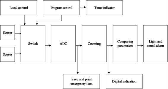
The system “Shipka” controlling parameters diesel MPP was the first domestic system of the centralized control, and its modification of “Shipka-M” has become the universal system.
The creation basis of the “Data logger” system by Fiat is the logical elements. Their installation takes place on cards with the printed schemes. Up to 16 standard elements are placed onto one card, then they are connected with plugs and place in the special ECR panel. The system is based on execution of NAND operation. The elements of schemes are executed with silicon
There is an opportunity to expand the functionality of the integrated hardware-software centralized control systems due to use of modern computer engineering and sensors. The use of microprocessor equipment increases reliability and effectiveness of the system and allows uniting of an emergency and warning signaling, protective systems, control systems and fault detection systems into a full complex.
Except central incorporating systems, there are systems with the distributed structure, which distribute functional units along the entire vessel (Fig. 2).
Fig. 2A complex system with the distributed structure of Kongsberg Company
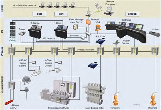
The automated systems collect all the information giving the operator the best review of a situation in general. The general information is shown at control station of any control system. The emergency shutdown system has to minimize the consequences of emergency situations connected with an uncontrollable process [4, 5].
The control system includes the preferred server and the event log server. These servers are connected via the pair of network interface controllers, having main and standby switches which are connected with each other and with routers which provide routing and the distribution of information between coastal and sea data networks with the help of satellite communication.
The design of a control system has a modular design, and consists of control stations and input-output modules, connected with local data networks. The control system is decentralized for the safety and the simplicity of installation, but it works centrally with the help of control stations. Each input-output module has a possibility of parameters’ alignment to correspond all the particular tasks of a certain system. The flexible design of a control system allows the linking up of additional input-output modules for a functionality extension. The modular design of system provides flexibility in a configuration of system to the individual system requirements from the systems with the low complexity degree of the alarm system to monitoring system with the advanced control process [4, 5].
The interaction of the operator is carried out through mimic diagrams at control station, or locally, from local control stations. The quantity of mimic in the system depends on the quantity of the equipment and systems which are under control. The main properties of the equipment characterizing it from a technical aspect and in the context of supervisory control and control were put into each mimic (for example, full-scale readings and the units of measurement of the sensor, a setting for an alarm generation, the need of an archiving, supplemental information, etc.). Then the objects which are directly attached to the concrete equipment were generated and adjusted from these patterns. The objects are grouped depending on a binding to process unit, units – to an operational space, etc. The logic tree of production with a possibility of specification of information at all levels is created as a result.
The systems created by SPA (science and production association) Avrora should be allocated from domestic integrated monitoring and control system. The EAS system has the centralized two-level hierarchy. The information and control system having information computer network is located at the top level. Monitoring systems are the lower level of hierarchy.
The actual problem of modern diesel engine manufacturing is a creation and a possibility of use of engine diagnostic system, and also the creation of the optimum functioning parameters’ calculation algorithms increasing the efficiency of operation. These systems raise a working life and reliability of the main ship engines, reduce expenses on service and repairs, and also energy resources expenses. A technical diagnostics of the engine is called a test of engine’s technical condition with a certain accuracy as a result of which there is a conclusion about technical condition of the engine with the designation of the place, a kind, and the reason of defect when necessary.
The creation of the first test systems of ship diesel engines began in the 30th years of the XX century. A that time the “Sulzer” firm began a development of systems of piston rings analysis, measuring pressure in an annulus. However, a creation of integrated systems began in 60-70th years. The experimental samples of the Predikat-1 and Predikat-2 system were investigated and created in Norway. These systems worked on the principle of a parametric technique. The current value of parameter was compared to reference one. On these parameter mismatch judged about the technical condition of the engine. Based on this system the “Norcontrol” company has created the “Datatrend” system which analyzes the generalized rates of engine’s technical condition. In the same years the Norwegian “Veritas” used the inductive sensors which are built into plugs controlling the technical condition of piston rings.
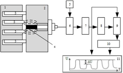
This type of the condition monitoring system of piston rings was widely used in a number of foreign systems. The “Sulzer” has installed in addition four thermal sensors, which define combustion process, a vibration of piston rings. Other two sensors define a condition of rings of details the alarm system activates at breakage.
Fig. 3The scheme of piston rings condition control: 1 − piston; 2 – cylinder liner; 3 – worn piston ring; 4 − inductive sensor; 5 – generator; 6 – signal transducer; 7 – data acquisition and storage block; 8 – storage unit; 9 – comparator; 10 – ring counter; 11 – representation device
The change of external features, at the engine operation in normal conditions happens due to a wear of the rubbing pairs. An emergence of knock happens because of the increased gaps in rod and main bearings. A dynamics of piston group’s work changes at wear of a cylinder face, a piston trunk and piston rings. At the same time a nature of vibrations and knocks, a break-in of exhaust gases into a crankcase and smoke changes. There is a possibility of an engine technical condition’s assessment Comparing the vibrations received at the analysis to vibration values of the initial and maximum permissible operating periods. There are various devices which measure separate parameters of vibration and can be gathered into the universal block scheme for simultaneous control of several parameters to make vibroacoustic control. Simultaneous control of all output ICE parameters is almost impracticable, and is economically inexpedient therefore it is chosen for the technical diagnostics of a parameters’ certain number. The greatest number of parameters is defined at a bench test, mooring and sea trials when the complex thermal tests of engines are carried out.
Its general state, the nature of processes running in it and, first of all, processes, making its cycle change in the course of engine’s continuous operation.
The main are the reasons:
• A wear of the CPG (cylinder-piston group) elements and a pollution of working cavities, including cooling systems, air supply and gas blades;
• A violation of a state and maladjustment of the fuel injecting equipment.
A change of fuel properties can also influence on a development of fuel’s ignition and combustion processes that distorts also a nature of operational process. The indicated changes lead to power reduction and efficiency, a decrease of resource and reliability, a growth of thermal and mechanical tension levels and, as a result to premature damages. A need, systematically, without being limited by control in the course of a watch service, to carry out a deeper check of its operational process and the general engine condition is defined by it.
The main foreign systems for a control of the parameters is possible to name the microprocessor MCS-5 and 6 system of MTU firm, the FAKS diagnostic system, created by the Wätrsilä Diesel, the NK-5 test system of AUTRONICA, the automated non-centralized system with PLC controlers of Control Measure Regulation (CMR), the monitor Simplot of ABB Industrietechnik AG, the parameters’ monitoring system of ship diesels’ operational processes DCS of Vista Ltd, the electronic monitoring system of ship engine’s operation of Kobelt Manufacturing Co., the electronic equipment Doctor of Icon Re-search for the control of diesels’ operational parameters of, etc.
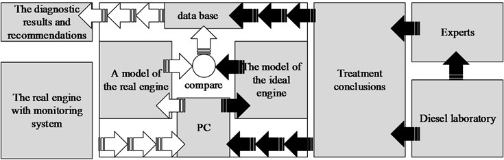
Let’s view a diagnostic system of Wätrsilä FAKS (Fault Avoidance Knowledge System) which is based on an expert analysis of the changes which have arisen at the change of engine’s technical condition. The majority of systems use mathematical methods of engine condition’s model which are necessary for a creation of diagnostic parameters’ reference values, and, therefore, a task solution is carried out with large errors. It is connected with many factors influencing the engine. It is difficult to execute the description of these factors mathematically. The FAKS system at the control of a certain engine is carried out in five stages. (Fig. 4). The expert in a certain type of engine creates the report on possible violations in engine operation which are compared to laboratory researches. After that there is an analysis of data, by means of computer processing. There is a data transmission into a model of the real engine after a collection of information from sensors There is an analysis of an ideal model and a real data from the engine after data collection and processing and the database and results of the diagnosis are created [6-8].
Fig. 4The block scheme of FAKS diagnostic system
The NK-5 test system of “AUTRONICA” (NORWAY) provides a control of diesels’ technical condition. The scheme of NK-5 diagnostic system’s structure is given in Fig. 6. Is included in the package of structure of system: the microcomputer, the mean indicated pressure computer with the display and the built-in disk drive for floppy disks, the printer.
For data acquisition and data processing and a condition of the engine the NK-5 system has a set of sensors.
1. A combustion pressure sensor of Piezoelectric type is established on the indicator cock of each cylinder, and as a portable unit is one for all cylinders. Pressure range – 0-160 bars, temperature – 0-300 °C.
2. A fuel pressure sensor of strain-gauge type is connected to high pressure pipelines and complete with the amplifier is used as portable one at an engine indication. Measurement range – 0-1000 bars, temperature of 0-150 °C. The pressure sensor of inductive type scavenging air measures pressure in the range of 0-4 bars.
3. The numeric and soft keyboard allows to control a processes of data acquisition, data processing and data representation on a display or a printer, and provides also operations with a disk which is used as an external storage.
A diagnostic of turbocompressor, the fuel equipment, cylinder-piston group, auxiliary systems of the engine were carried out by the SS-10 system of production by B&W and STL, but after maintenance check has shown a low reliability and efficiency.
The “Norcontrol” system of DETS is a measuring complex controlling an injection of fuel and a combustion process. The system has two piezoelectric sensors controlling a pressure of fuel injection and a pressure in a cylinder. The system plots a diagram of compression pressure and a curve of injection pressure.
The system of ASEA Sildet-SM controls plug temperature at a depth of 3 mm and 10 mm, a gap between piston rings and the cylinder plug, wear of the cylinder plug.
The system of Pielstick PED firm controls a condition of crank shaft’s main bearings and the top piston ring’s main bearings that have become possible owing to the use of noncontact displacement transducer.
The MEKOM system of Statronic firm (Norway) is applied on diesels, turbines, boilers. The system registers the vibration level of mechanisms, temperatures of turbines’ bearings, cylinder plugs,
The MEDIAG-22 system of Siemens controls cylinder-piston group ТА and ТK.
The problem of equipment’s reliability appears due to continuous MPP complication. For the increase of equipment’s reliability, the information technologies are used. Analyzing engine’s test systems, it is possible to draw a conclusion that the essence of malfunctions diagnostic’s undemounted methods is that features are investigated and any parameters (group of parameters) of the operating engine are measured. The obtained data are compared with standards of admissible limits established on serviceable and the adjusted engines. As a result of the analysis, the general conclusion about engine’s technical condition becomes and the decision on its repair is made [3-9]. An application of undemounted methods of engine technical condition’s fault detection with the use of engine’s test system in the propulsion plant gives considerable economic results: the optimum conditions of operational parameters’ adjustment influencing on the efficiency of ME operation and details’ wear are created; critical conditions of the ME are warned; the conditions running-in of the linked details remain. As a result, reliability and durability increases, the interrepair time increases and costs of repair of the ME are reduced.
References
-
Lanchukovskny V., Kozminykh A. Automated Control System of Marine Diesel and Gas Turbines. 1983.
-
Kornilov E. Ship Main Engines with Electronic Control. Express-Advertising, 2010.
-
Miroschnik I. The Theory of Automatic Control. SPb, 2005.
-
Korneev N. Automatic Control Theory with Workshop. 2008.
-
Chernyi S. Analysis of the energy reliability component for offshore drilling platforms within the Black Sea. Neftyanoe Khozyaystvo – Oil Industry, Vol. 2, 2016, p. 106-110.
-
Chernyi S. Techniques for selecting topology and implementing the distributed control system network. International Conference on Mechanical Engineering, Automation and Control Systems, IOP Conference Series: Materials Science and Engineering, Vol. 124, Issue 1, 2016, p. 12048.
-
Chernyi S., Zhilenkov A. Modeling of complex structures for the ship’s power complex using XILINX system. Transport and Telecommunication, Vol. 16, Issue 1, 2015, p. 73–82.
-
Chernyi S. Use of information intelligent components for the analysis of complex processes of marine energy systems. Transport and Telecommunication Journal, Vol. 17, Issue 3, 2016, p. 202-211.
About this article
