Abstract
According to longitudinal vibration differential equations of ship propulsion shafting, deduced transfer matrix of propeller, uniform shaft segment and thrust bearing which composed propulsion shafting. Given longitudinal vibration natural frequency of propulsion shafting using the transfer matrix solver, and compared with finite element simulation results to verify the accuracy of the finite element model. Then analysis the effect of elastic coupling axial stiffness on modal frequencies of shafting longitudinal vibration and vibration isolation performance through simulation. Results show that: elastic coupling can effectively isolate the propulsion shafting vibration transmitted to the propulsion motor; when the axial stiffness ratio of thrust bearing and elastic coupling is greater than 50, the impact of elastic coupling axial stiffness on longitudinal vibration natural frequency of propulsion shafting and acceleration level and axial displacement of thrust bearing is very small; when the stiffness ratio is greater than 100, the elastic coupling can achieve better vibration isolation effect.
1. Introduction
With the development of shipbuilding technology, people put forward increasingly high requirement on security, reliability and comfort of power system. Elastic coupling is widely used in modern ship power device to solve the vibration and noise problem of shafting [1]. It is set in the propulsion motor output terminal and its function lies in transmit torque, adjust shafting torsional vibration characteristics, compensate for the vibration displacement caused by the impact of the driving and driven shafts, buffer and absorb vibration. It can reduce vibration and noise and protect the entire driving system, has great ability to support load and compensate displacement.
Since the 1960s, developed countries have developed a Geislinger, Fu Kang and other new coupling, widely used in a variety of transmission devices. China in the late 1970s started to develop high elastic couplings, such as XL rubber metal ring coupling and the introduction of technology to produce Geislinger couplings [2]. Literature [3] use LS high elastic coupling as the research object, studied the prediction technology of vibration isolation performance of high elastic coupling combining software simulation and experimental validation method, but did not consider influence factors of vibration isolation performance; literature [4] use vibration level difference as evaluation index, studied the effect of elastic rubber and diaphragm on natural frequency of axial, radial and torsional direction and vibration level difference of elastic coupling; literature [5] established the simulation model of elastic rubber component of a certain type high elastic coupling using the ABAQUS software, and analyzed its axial displacement and axial force at work station.
In this paper, we took a ship shafting for the study, analyzed the vibration isolation performance and influencing factors of elastic coupling using finite element method under longitudinal excitation of propeller.
2. Mathematical model of propulsion shafting
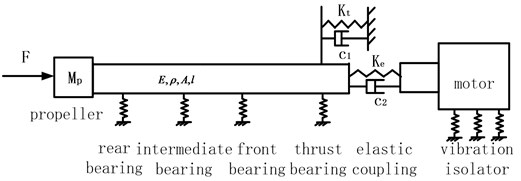
Propulsion shafting is composed of propeller, stern shaft, thrust shaft, stern shaft rear bearing, stern shaft intermediate bearing, stern shaft front bearing, thrust bearing, elastic coupling, propulsion motor and propulsion motor vibration isolator. The simplified model of propulsion shafting is shown in Fig. 1.
Fig. 1Simplified shafting model
When the shafting vibrate freely, namely 0, according to Newton’s laws of motion, the equation of motion for the propeller is:
where is displacement and is force. Then, consider of , written in matrix form is:
We can get the propeller transfer matrix:
The stern shaft is simplified as uniform shaft segment, and its longitudinal free vibration equation is:
The transfer matrix of uniform shaft segment can be obtained by solving the equation:
where .
For shafting, the quality of the thrust bearing is not involved in longitudinal vibration of shafting, in the case of ignoring damping, thrust bearing can be simplified to a massless spring. Due to the great quality of propulsion motor and great quantity and lateral stiffness of motor isolator, so the connection of elastic coupling to the motor can be simplified as connected to a fixed, elastic coupling can be simplified to three massless linear spring and torsion spring. Thus, the output boundary conditions of the thrust bearing can be simplified as two parallel spring support. Displacement and force around the end of massless linear spring have the following relationship:
Therefore, the transfer matrix of the massless linear spring is:
The total transfer matrix is:
The boundary condition of the shafting model is:
We can get the remaining amount .
Set 0:
3. Finite element model of propulsion shafting
3.1. Model parameters
Taking the propulsion shafting of a ship for example, the model parameters are shown in Table 1.
3.2. Finite element model
Finite element model of propulsion shafting established by using software Patran is shown in Fig. 2. Shaft segment is a homogeneous hollow shaft using hexahedral elements said, propeller using lumped mass instead. Without considering the non-linear of bearing stiffness, connections between shaft segment and stern bearings and thrust bearing are considered as linear spring support; elastic coupling use rubber Mooney-Rivlin model [6], propulsion motor use hexahedral solid element simulation, the motor is connected to the base through six vibration isolators.
As can be seen from Table 2, the first 5 order modal frequencies of the shafting longitudinal vibration calculated by transfer matrix method are smaller than simulation results, but the errors are less than 4 %. Visibly, in the study of shafting longitudinal vibration, simplified elastic coupling as three linear springs and one torsion spring and elastic coupling output end as rigid fixation are feasible, with high accuracy.
Fig. 2Finite element model of shafting
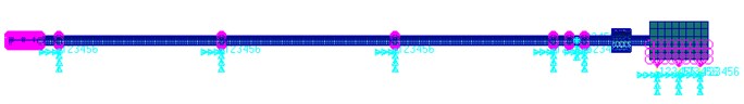
Table 1Model parameters
Parameter | Value | Parameter | Value |
Shafting length / m | 15.6 | Shafting outer radius / m | 0.27 |
Shafting inner radius / m | 0.12 | Propeller mass / kg | 3800 |
Motor mass / kg | 11700 | Stiffness of stern shaft rear bearing / n·m-1 | 1.5e+08 |
Stiffness of stern shaft intermediate bearing / n·m-1 | 1.5e+08 | Stiffness of stern shaft front bearing / n·m-1 | 2.0e+08 |
Radial stiffness of thrust bearing /n·m-1 | 3.0e+08 | Axial stiffness of thrust bearing / n·m-1 | 1.2e+09 |
Radial stiffness of elastic coupling / n·m-1 | 1.74e+09 | Axial stiffness of elastic coupling / n·m-1 | 1.2e+07 |
Torsional stiffness of elastic coupling / n·m-1 | 5.2e+08 | Transverse stiffness of motor vibration isolator / n·m-1 | 1.6e+08 |
Vertical stiffness of motor vibration isolator / n·m-1 | 1.1e+08 | Material density / kg·m-3 | 7.85e+03 |
Elastic modulus / n·m-2 | 2.10e+11 | Poisson’s ratio | 0.3 |
Table 2Modal frequencies
Modal order | 1 | 2 | 3 | 4 | 5 |
Calculate result | 39.50 | 144.25 | 285.70 | 442.88 | 605.63 |
Simulation result | 40.78 | 149.97 | 295.73 | 457.81 | 627.27 |
Error | 3.13 % | 3.81 % | 3.39 % | 3.26 % | 3.45 % |
4. Vibration isolation effect of elastic coupling
4.1. Effect of axial stiffness of elastic coupling on modal frequency of shafting
The effect of axial stiffness of elastic coupling on first 5 modal frequencies of shafting longitudinal vibration is shown in Table 3. In order to make the analysis result to be universal, the axial stiffness of elastic coupling is treated by non-dimensional, taking ratio of the axial stiffness of thrust bearing and elastic coupling as the variable.
Table 3Effect of axial stiffness of elastic coupling on the modal frequency of shafting
Modal order | Rigid connection | 1000 | 500 | 100 | 50 | 10 |
1 | 58.28 | 40.70 | 40.71 | 40.78 | 40.89 | 41.71 |
2 | 189.84 | 149.75 | 149.77 | 149.97 | 150.21 | 152.05 |
3 | 344.22 | 295.54 | 295.56 | 295.73 | 295.93 | 297.52 |
4 | 502.06 | 457.68 | 457.69 | 457.81 | 457.96 | 459.09 |
5 | 659.56 | 627.17 | 627.18 | 627.27 | 627.37 | 628.17 |
As can be seen from Table 3, after the installation of elastic coupling, the first 5 order modal frequencies of propulsion shafting longitudinal vibration decrease; when axial stiffness ratio of thrust bearing and elastic coupling decreases from 1000 to 50, the first 5 order modal frequencies of shafting longitudinal vibration increase, but the variation is very small; when axial stiffness ratio of thrust bearing and elastic coupling decreases from 50 to 10, the first 5 order modal frequencies of shafting longitudinal vibration increase 1-2 Hz.
4.2. Vibration isolation effect of elastic coupling
Axial displacement of propulsion shafting must meet requirement about allowed axial displacement of the standard on ship stern seal device. Simultaneously, axial displacement of the shafting has great impact on propulsion motor. Therefore, we choose axial displacement of the shafting, vibration acceleration level and insertion loss as evaluation of vibration isolation effect of elastic coupling in the following.
Under unit longitudinal excitation force at the end of propeller, when the shaft connected to the motor output rigidly and elastically, displacement frequency response curve of the thrust bearing and elastic coupling output end are shown in Fig. 3.
Fig. 3Displacement of thrust bearing and elastic coupling output end
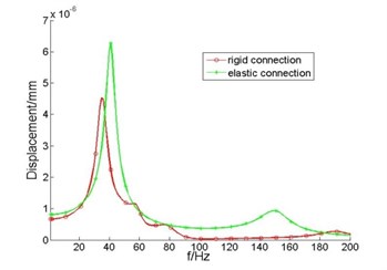
a) Thrust bearing
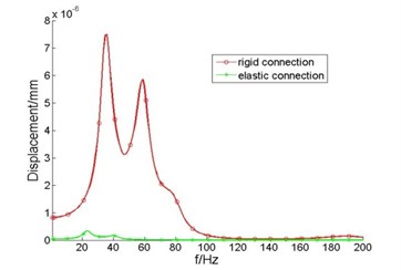
b) Elastic coupling output end
It can be seen from the Fig. 3(a) that, after the installation of elastic coupling, displacement peak of the thrust bearing moves to low-band, and increases compared with rigid connection, especially at the first and second modal frequencies of shafting. This is because, compared with rigid connection, after the installation of elastic coupling, axial stiffness of the thrust bearing is reduced, under the same exciting force, will inevitably lead to increased displacement response. However, displacement of the elastic coupling output end decreased, this is because the connection of motor output end and shaft becomes elastically instead of rigidly after installing elastic coupling, mechanical impedance of the thrust bearing to the motor output increases.
Fig. 4Acceleration level and insertion loss of elastic coupling output end
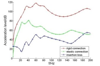
Before and after the installation of elastic coupling, vibration acceleration level and insertion loss of elastic coupling output end are shown in Fig. 4.
It can be seen from Fig. 4 that, after the installation of elastic couplings, vibration acceleration level of elastic coupling output end decreased significantly. In less than 40 Hz, the insertion loss is 15-30 dB; in 40-200 Hz frequency band, insertion loss reaches 40 dB, vibration isolation effect is obvious. This is because in addition to transmit to thrust bearing base, there are a considerable part of shafting vibration at the thrust bearing transmitted to the propulsion motor under rigid connection; after the installation of elastic coupling, it is equivalent that there is an vibration isolator between the thrust bearing and propulsion motor. Since the axial stiffness of elastic coupling is much smaller than thrust bearing, shafting vibration mainly transmitted to the hull through thrust bearing base.
4.3. Effect of elastic coupling stiffness on vibration isolation efficiency
The elastic coupling is equivalent to a vibration isolator installed between the thrust bearing and propulsion motor. The stiffness of the isolator is an important factor to influence the vibration isolation effect. In the following, effect of elastic coupling axial stiffness on the vibration isolation efficiency is analyzed.
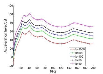
As the axial stiffness ratio of thrust bearing and elastic coupling changes, frequency response curves of displacement and vibration acceleration level at the thrust bearing are shown in Fig. 5.
Fig. 5Displacement and acceleration level of thrust bearing
a) Displacement
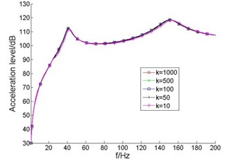
a) Acceleration level
It can be seen from Fig. 5 that, as the axial stiffness ratio of thrust bearing and elastic coupling reduced from 1000 to 50 (elastic coupling axial stiffness increases), displacement and acceleration level did not change significantly at the thrust bearing; when the axial stiffness ratio of thrust bearing and elastic coupling reduced from 50 to 10, the displacement of thrust bearing decreases. This is because the elastic coupling and thrust bearing base equivalent to two parallel spring providing longitudinal support for thrust shaft, when the axial stiffness ratio of thrust bearing and elastic coupling is larger than 50, the axial stiffness of thrust bearing is much greater than that of elastic coupling, the effect of elastic coupling and propulsion motor on the thrust shaft is small and can be neglected; as the axial stiffness ratio of thrust bearing and elastic coupling reduced increasingly, axial stiffness of elasticity coupling is closer to that of the thrust bearing, the shaft axial stiffness in the thrust bearing becomes bigger, so the displacement response of thrust bearing is reduced. It also shows that when the axial stiffness ratio of thrust bearing and elastic coupling is greater than 50, the effect of elastic coupling axial stiffness on the thrust shaft is small and can be neglected.
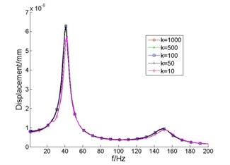
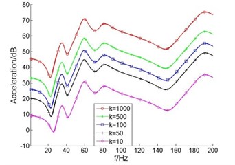
As the axial stiffness ratio of thrust bearing and elastic coupling changes, frequency response curves of displacement and vibration acceleration level of elastic coupling output end are shown in Fig. 6.
It can be seen from Fig. 6(a) that, as the axial stiffness ratio of thrust bearing and elastic coupling reduced from 1000 to 100, displacement of the elastic coupling output end changes little; displacement amplitude of elastic coupling output end doubled when stiffness ratio reduced from 100 to 50; when the stiffness ratio reduced from 50 to 10, the displacement amplitude of elastic coupling output end increased by almost 3 times. You can see from Fig. 6(b), as the axial stiffness ratio reduced from 1000 to 50, the acceleration level of elastic coupling output end increases, but the amplitude was small; as the stiffness ratio reduced from 50 to 10, the acceleration level of elastic coupling output end increased significantly, vibration amplitude at the first order modal frequency is close to the amplitude of the thrust bearing, vibration isolation efficiency decline seriously.
Fig. 6Displacement and acceleration level of output end of elastic coupling
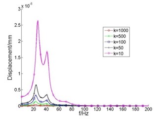
a) Displacement
a) Acceleration level
Fig. 7Insertion loss of elastic coupling
As the axial stiffness ratio of thrust bearing and elastic coupling changes, frequency response curves of insertion loss of elastic coupling are shown in Fig. 7.
It can be seen from the Fig. 7 that, as the axial stiffness ratio of thrust bearing and elastic coupling decreases, the insertion loss of elastic coupling decreases; when the stiffness ratio is smaller than 100, the insertion loss of elastic coupling at 23 Hz is only about 10 dB; when the stiffness ratio is greater than 100, the insertion loss of elastic coupling in the entire frequency range of within 200 Hz are more than 20 dB, in the frequency range of above 40 Hz, average insertion loss is around 40 dB, vibration isolation effect is very good.
5. Conclusions
By simplifying shafting model, calculate longitudinal vibration modal frequencies of shafting using transfer matrix method and compared with finite element result; choose axial displacement, vibration acceleration level and insertion loss as evaluation, simulate the vibration isolation efficiency of elastic coupling and the influence of axial stiffness on the longitudinal vibration modal frequencies and vibration isolation efficiency, obtained the following conclusions:
1) Simplified elastic coupling to three linear springs and one torsional spring is of high accuracy when study longitudinal vibration of shafting and the nonlinear characteristics of the elastic coupling are not considered.
2) When the axial stiffness ratio of thrust bearing and elastic coupling is greater than 50, the effect of elastic coupling axial stiffness on the longitudinal modal frequencies and the displacement and acceleration level of the thrust bearing is very small and can be neglected.
3) Compared with rigid connection, after the installation of elastic coupling, the axial displacement of thrust bearing is increased, but the vibration transmitted from the shaft to the motor is significantly reduced, and the vibration isolation effect is obvious.
4) The smaller the axial stiffness of elastic coupling, the better the performance of vibration isolation and the compensation performance of axial displacement. But the ship shafting usually need to transfer large torque, torsional stiffness cannot be too small, in order to ensure good vibration isolation performance of the elastic coupling, while ensuring the shafting stability, it’s better to set the axial stiffness ratio of thrust bearing and elastic coupling at about 100 or so.
References
-
Zhang Yun High elastic coupling for ship power plant. Ship and Boat, Vol. 1, 2006, p. 34-38.
-
Lin Ruilin, Huang Cihao Survey of development and application of highly flexible couplings on ships. Journal of Naval University of Engineering, Vol. 13, Issue 2, 2001, p. 49-53.
-
Ye Yongyong, Ye Linchang, Zhang Dong Research on the performance forecast of the vibration isolation for the high flexible couplings. Diesel Engine, Vol. 34, Issue 4, 2012, p. 44-47.
-
Wen Huabing, Zhong Qidong Research on the vibration transmission characteristics of the high-elastic coupling. Journal of Jiangsu University of Science and Technology (Natural Science Edition), Vol. 29, Issue 3, 2015, p. 251-255.
-
Xi Caoliang, Peng Yijun, Chu Hongsen The simulation analysis of axial force of the highly flexible coupling’s rubber element. Noise and Vibration Control, 2009, p. 72-75.
-
Lu Hui, Ding Chunhua, Huo Zhaobo Static characteristic analysis of the high-torsion flexible coupling. International Conference of Power Transmission, Vol. 35, Issue 10, 2011, p. 16-20.
-
A. I-Hussain K. M., Redmond I. Dynamic response of two rotors connected by rigid mechanical coupling with parallel misalignment. Journal of Sound and Vibration, Vol. 249, Issue 3, 2002, p. 483-498.
About this article
