Abstract
With the assumption t at the motion acceleration of the cargo is unknown, the dynamic model that accords with the engineering practice of sequential cargo airdrop operations is derived by using the separation body method, which can describe the impact of the sequential moving cargos on the flight safety and airdrop-mission capacity. On this basis, a novel flight control method is designed based on the active disturbance rejection control (ADRC) theory. the system is decoupled and linearized through the nonlinear state error feedback; the total unknown disturbances, including unmolded dynamics and uncertainty, are estimated and compensated real-timely by the extended state observer. Moreover, with the consideration of the time-delay system, the ADRC is improved to enhance the accuracy and rapidity of the control system. Simulations are carried out under the condition that one transport aircraft performs sequential airdrop operations. The results verify that the desirable performance and robustness have been achieved and the proposed control method is quite competent for the sequential airdrop operations.
1. Introduction
With the remarkable performance for quick delivery and disposition of troops and equipments, heavyweight airdrop has been playing an indispensable role in modern warfare. To take full advantage of the superiority in avoiding enemy radar detection, improving cargo delivery accuracy and minifying the damage risk of the payloads, ultra-low altitude sequential airdrop becomes an essential capability of a large transport aircraft [1, 2]. During the sequential airdrop process, the pitch angle of the carrier rises constantly under the stress of pitch moment exerted by the gradual rearward goods, and followed by a fierce bow because of a sudden extraction of the cargos [3, 4]. Thus, the aircraft suffers large and sudden disturbances exerted by the cargos one after another. Together with the strong coupling between the cargos and aircraft dynamics, and multiple uncertainties, the aircraft states will be sensitive to whatever disturbance, and even to result in a fatal crash [5]. To cope with the intricate and challenging problem mentioned above, to design an effective controller for the sequential airdrop operations is crucial to the task performance and the flight safety.
Over recent years, some significant achievements have been made in designing control methods for strong nonlinear system with uncertainty. Variable structure control has advantage of insensitivity to parameter changes and disturbances, removal of needs for the on-line model identification, and simplicity in mechanical implementation [6]. But it deals with the case in which upper bounds on the unknown nonlinearities are known and the control is devised based on the bounds; therefore, this method tends to be conservative, sometimes leading to high-frequency flutter. Feedback linearization transfers the complex nonlinear model to the simple one, and achieves the decoupling control [7]. However, this method depends on the accurate knowledge of the dynamic model; it is not the case with the heavyweight airdrop flight control project, since there always exits unmolded dynamics. The control method, in theory, could obtain a perfect performance, and doesn’t rely on the precise model of the system [8]; while its performance will deteriorate constantly with the growth of the cargo weight. Besides the methods mentioned above, the development of online learning methods and algorithm have provided efficient reference for the solution of the uncertainty during the airdrop process [9-13].
Moreover, compared with the single-cargo airdrop, the sequential operations pose a stronger nonlinear and decoupling dynamics. The methods mentioned above are less effective to the single-cargo airdrop operations, let alone to the sequential. In conclusion, a novel controller should be designed with the consideration of being practical to the physical reality, meeting the airdrop task demand and satisfying the flight safety requirement [14-15].
Active disturbance rejection control (ADRC) is a nonlinear method developed by professor Han [16]. This method employs the core of PID controller that basis on adopting error-feedback to regulate system, and the states error is eliminated without relying on accurate system model. Various disturbances, both in external and interior, are boiled down to “total uncertainty” and estimated through the extended state observer (ESO) [16-18]. And then, by real-time compensation for system states, we can obtain the linearized model. Combined with nonlinear state error feedback, the controller acquires an efficient performance. Applications in many industrial fields with ADRC controller show the good effectiveness of the method.
The study in this paper is done to cope with the problem emerges from the sequential airdrop process. Firstly, the dynamic model of the sequential airdrop operations is derived. Secondly, the closed-loop control system based on ADRC technique is put forward for the airdrop task demands and flight safety. In addition, to validate the rationality of the dynamical models and control system, the real-time simulation is carried out and results demonstrate its effectiveness.
2. Dynamics modeling of the aircraft-cargo during airdrop process
To design a reasonable flight controller, an aircraft-cargo dynamic mode which coincides well with the airdrop reality is essential. Until now, two types of modeling approaches, including the combination body method [3, 19] and the separation body method, [4, 6, 11] are available from the literature. While the common defect of these two approaches is the assumption that the cargo moving backward to the rear door with a constant acceleration, which inevitably introduces some model error since the component force along the motion-rail increases continuously.
To simplify the derivation of the mode, several reasonable assumptions are made:
(a) The aircraft can be viewed as a rigid body;
(b) The cargo is considered as a particle, and the mass of every single cargo is equal.
(c) The initial position of each cargo is the center of the gravity of the aircraft.
(d) The rail cargo moves along coincides with the aircraft longitudinal body axis.
When the aircraft arrived above the object region, the first cargo will be dragged backward by the parachute and extracts from the aircraft suddenly. seconds later, the second cargo begins moving. Thus, all of the cargos will be delivered in sequence. we can resort to the separation body approach to build the dynamic model of this operation.
Fig. 1Definition of coordinates and analysis of forces of the aircraft
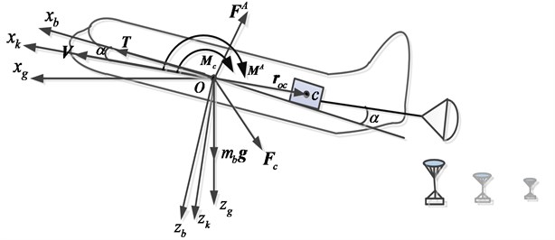
2.1. Aircraft dynamics
The coordinates definition and forces analysis are illustrated in Fig. 1, where is the center of the gravity of the aircraft, is the earth frame, is the body-fixed frame and is the cargo’s track-axes frame. is the mass of the aircraft without payloads. is the attack angle, is the gravity acceleration, is velocity of the aircraft. is aerodynamic force vector, is aerodynamic moment vector. is the disturbance force exerted by cargos, is the disturbance moment caused by cargos, is the engine thrust, is the position vector of the cargo that is moving to the rear door.
The longitudinal dynamic equation of the aircraft can be described as:
where is the momentum of the aircraft. According to the forces analysis, it is obvious that cargos affect the longitudinal dynamics of the aircraft but does not influence the lateral. Thus, we can obtain:
where , and stand for the unit vector of the , and , respectively. is the pitch moment of the inertia, is the pitch rate, is the pitch acceleration, and stand for the drag force and lift force, respectively, is the pitch aerodynamic moment, is the pitch moment exerted by the cargos, and denote the components of the along and .
Eq. (1) and Eq. (2) can be expressed as:
where , and represent the climb angle, pitch angle and angle of attack (AOA), respectively. And the aerodynamic forces and moment can be found by:
where is the dynamic pressure; is the wing area; [–25°,…, +25°] is the elevator deflection; is the mean aerodynamic chord; and are the pitch moment coefficients and , are the lift and drag coefficients, respectively.
The engine thrust is:
where is the maximum thrust of the engine, (0, 100 %) is the throttle.
2.2. Cargos dynamics
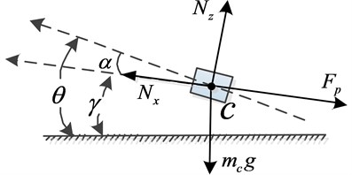
For each cargo that is moving to the rear door, as shown in Fig. 2 the forces and moments exerted on the cargo are the resultant force vector , the parachute drag force which point to the direction of the . And is the mass of each single cargo.
Fig. 2Forces analysis of the moving cargo
As the movement of the cargo is the relative motion to the aircraft, the absolute acceleration of the center of the gravity consists of transport acceleration , Coriolis acceleration and relative acceleration :
where denotes the angular velocity vector of the aircraft. stands for the relative derivative operator. Then, can be expanded in the track-axes frame as:
where and are the and components of in the track-axes frame.
According to Newton’s Second Law, the dynamic equation of the cargo can be obtained as:
And the friction caused by the cargo’s pressure can be found by:
where is the friction coefficient.
According to the Eqs. (7)-(10), we can obtain:
with:
2.3. The interaction between the aircraft and cargos
For the aircraft, the influence exerted by the cargos including the force and moment . There are two types of the cargos that affect the dynamics of the aircraft, including one moving cargo which is being delivered and several fixed cargos that are still locked at the initial position.
(1) The moving cargo produces the effect and moment . And according Newton’s Third Law, we can obtain that:
(2) The fixed cargos only produce the force , and do not exert the pitch moment according to the Assumption (c):
where is the number of cargos. Then, the force caused by the cargos is:
According to Eqs. (3)-(17), we can rewrite the aircraft-cargo model:
Where:
and is the uncertainty of each state channel.
3. Control system design
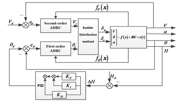
During the airdrop process, cargos are pulled out of the deck one after another by the extraction umbrella. To guarantee the airdrop precision and flight safety, the flight states should be stabilized as far as possible. Therefore, the object of the controller is to keep the states in the trim position. According to the dynamics modeling, the AOA is not affected directly by the controlled quantity , which can be regulated with the altitude , pitch angle and airspeed according to the relationship . Therefore, the controller is designed for tracking the desired instructions of the and to maintain the longitudinal states during the sequential airdrop process. Meanwhile, a holder for flying altitude of the aircraft is essential to the flight safety and task requirement. As shown in Fig. 3, the framework of the control system is integrated by the inner loops for airspeed and pitch angle stabilization and PID controller in outer loop for altitude holding.
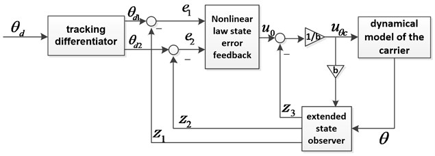
For the airspeed and pitch angle , designing the first-order and second-order ADRC controller, respectively. Since the similar principle of two channels, here we take the sub-loop of the pitch angle as an example to introduce the ADRC controller. As illustrated in Fig. 4, the controller for the pitch angle consists of tracking differentiator (TD), nonlinear law state error feedback (NLSEF) and extended state observer (ESO). Let denotes the trim pitch angle.
According to the , the TD produces the input of the controller:
where is the tracking parameter, which determines the rate of the TD for tracking the input, the signal function is used to reduce the difference between and . Thus with the transient process to prevent an excess input, to provide the differential signal shielding the noise interference.
The aircraft states , and the external disturbance are estimated by the ESO:
where , 1, 2, 3 are feedback coefficients, , are the estimations of the pitch angle and angle rate, is the estimation of “total disturbance” (the extended state) which contains the external disturbance and the internal dynamics .
with the nonlinear exponential and saturation zone is the time optimal control function to approximate the states instantly but without high frequency flutter: , , [20, 21].
Fig. 3Framework of the control system
The error feedback quantity is obtained from the NLSEF, and the nonlinear feedback is more efficient than the linear one in eliminating the error [16, 18]:
where , is the nonlinear feedback coefficient.
Then:
Combining Eq. (18) and Eq. (22), we can obtain that:
Thus, a nonlinear system with unknown disturbance and uncertainty is transferred into a first-order linear equation; it’s well-known that the model is easy to be controlled.
Moreover, in the inner loop, the airspeed and pitch angle are controlled by the first-order and second-order ADRC controllers, respectively. We can obtain the desired instructions and through the decoupling control. Both the elevator deflection and the throttle opening have effect on the airspeed and pitch angle at the same time, and a proper control surface distribution method is necessary to realize the requirement to both of them. Since , then:
Through state feedback and disturbance compensation, we can obtain the desired responses.
In the outer loop, a PID controller is employed to hold the flight altitude. The structure of the height controller is shown in Fig. 4, where is the current flying altitude, is the desired command of ; , and represent the proportion, integration and differentiation gains, respectively.
Fig. 4Second-order ADRC controller block for pitch control
4. Improvement of ADRC controller
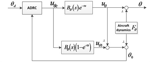
The ADRC controller is suitable for strong nonlinear system with much interference. However, since the instant feedback for error, the existence of the time-delay between the controller and actuator always results in worse effect. When considering the time delay, the dynamics of pitch angle loop can be transformed to the complex frequency domain:
where denotes the signal of Laplace transform, , , and denote the Laplace transform expression of , , and , respectively, is the length of delay time.
The pitch angle controlled quantity obtained by the controller in the time is , but the factual input to the aircraft is due to the time delay, which will lead to an inaccurate result. To eliminate the impact of delay, as shown in Fig. 5, the pitch angle is processed to :
Thus, there is not the time delay for the input to , Eq. (26) can be transferred to:
Since:
Thus:
which implies that the contains the information of delay time . Through the feedback of to replace , the impact of time delay can be eliminated.
Fig. 5Schematic of improved ADRC controller for time-delay system
Based on the excellent filter capacity of the TD, the improved ADRC control law for time-delay systems can be expressed as:
The parameter can be adjusted according to the length of the time delay to improve the accuracy of the controller.
5. Simulation and analysis
Simulate the sequential airdrop mission of a certain transport aircraft at the altitude of 10 m with 4 cargos, and the mass of each cargo is 2,000 kg. The cargos are locked in the aircraft initially and do not produce pitch moment to the carrier. the airdrop operation starts with the condition: 10 m, 80 m/s, and 2.5269, the engine thrust 38435 N, the flap deflection 25 , the drag force of the parachute is with drag rate 0.2. The interval time of two adjacent cargos’ delivery 3 s, and the coefficients of the controller are shown in Table 1.
Table 1Coefficients value of the controller
Coefficient | Value | Coefficient | Value | Coefficient | Value |
100 | 0.0025 | 50 | |||
0 | 0.8 | 0.5 | |||
0.0025 | 0.6 | 0.0025 | |||
0.5 | 0.0025 | 1.8 | |||
0.002 | 10 | 0.5 | |||
0 | 0.56 | 0.0025 | |||
0.0025 | 0.0025 | 1.2 | |||
10 | 30 | 0.04 | |||
10 | 0 | 0.025 | |||
0.5 | 0.002 | 0.0065 |
Fig. 6Aircraft responses in sequential cargo extraction without controller
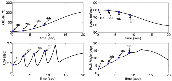
Fig. 7Aircraft responses in sequential cargo extraction with the proposed controller
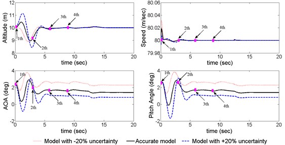
As illustrated in Fig. 6, when four cargos are dropped from the transport orderly, the aircraft states without control change instantly and fiercely, which has been far beyond the flight safety-boundary [5]. To verify the control performance and robustness of the proposed control method, we hypothesize that the aerodynamic coefficients exit ±20 % uncertainty the successful implementation of the control law can be observed from Fig. 7. Among all the three cases, the altitude is maintained within the range of [8.5, 11.2] m though being subjected to the large disturbance of the cargos and uncertainty. The airspeed fluctuates lightly compared to the open-loop response, the pitch angle and the AOA are also controlled in the range of 3°. It can be seen that the controller is capable to be employed to the sequential airdrop operations.
The effectiveness of the ADRC controller is mainly determined by the capacity of the ESO that executes the estimation for the total disturbance. From the results depicted in Fig. 8, we can conclude that the ESO estimates the total disturbance perfectly both in airspeed channel and the pitch angle channel, which explains the reason of the effective control capacity and robustness to a large extent.
Fig. 8System total disturbance and its estimation
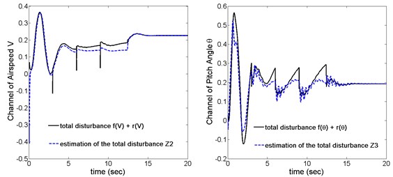
Fig. 9Responses of elevator and throttle
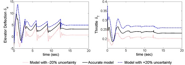
Fig. 10Responses of aircraft with time delay
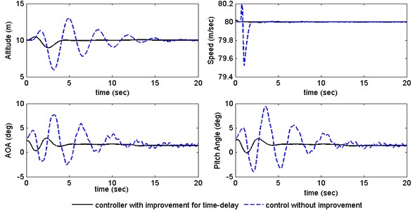
Fig. 9 shows that the response of the elevator and throttle with ±20 % uncertainty; both the elevator deflection and the engine throttle are within the available range, which means the control law is feasible to practical applications. Compared the response with the proposed controller to the one without controllers in the Fig. 10, it is clear that the improved ADRC achieves high-precision and rapid control performance in the presence of 1.5 seconds’ delay. In summary, the proposed control method meets the requirements of the sequential airdrop.
6. Conclusions
1) With the reasonable preconditions close to the engineering reality, the nonlinear model of the aircraft for sequential cargos airdropping is established through the analysis of the interaction between the cargos and aircraft. The open-loop simulation for 4 cargos sequential airdrop indicates that the flight safety has been seriously threaten by the disturbance of the moving cargo, which lays the foundation for analyzing the influence of the moving cargo on the flight states and control law design.
2) A novel control strategy for sequential airdrop operations is proposed for the inner-loop speed and pitch angle control of the carrier and the altitude controller for the outer-loop. This control method can guarantee the safety of the strong nonlinear system with uncertainty by introducing the ADRC controller, which can estimate and compensate the uncertainty timely under the condition of inaccurate system model. Moreover, considering the practical case of time delay, the ADRC controller is improved through the input forecast to increase the control precision, thus enhancing the practicality of the controller.
3) The performance of the proposed control system is evaluated by four cargo sequential airdrop mission at an ultra-low altitude. Simulation results show that the strategy can control the flight states to meet the flight safety and airdrop mission performance demands even in the presence of ±20 % parameters perturbation and delay time.
The research results will benefit the future implementation of the sequential airdrop missions. While the presentation of this paper has assumed that the locked cargos have no torque disturbance to the aircraft. This is, of course, an idealized situation. Moreover, the ADRC theory provides an effective control approach for nonlinear systems, further studies in tuning methods of the controller parameters is needed at the same time, and this will be one of our future studies.
References
-
Desabrais K. J., Riley J., Lee C. Low-cost high-altitude low-opening cargo airdrop systems. Journal of Aircraft, Vol. 49, Issue 1, 2012, p. 349-354.
-
Jann T. Coupled simulation of cargo airdrop from a generic military transport aircraft. AIAA, Report No. 2011-2011-2566, 2011.
-
Chen J., Shi Z. K. Aircraft modeling and simulation with cargo moving inside. Chinese Journal of Aeronautics, Vol. 22, Issue 2, 2009, p. 191-197.
-
Pang S., Ng E., Chiu W. S., et al. Comparison of turbulence models in near wake of transport plane C-130H fuselage. Journal of Aircraft, Vol. 50, Issue 3, 2013, p. 847-852.
-
Raissi K., Mani M., Sabzehparvar M. A single heavy load airdrop and its effect on a reversible flight control system. Aircraft Engineering and Aerospace Technology, Aircraft Engineering and Aerospace Technology, Vol. 80, Issue 4, 2008, p. 400-407.
-
Zhang H. Y., Shi Z. K. Variable structure control of catastrophic course in airdropping heavy cargo. Chinese Journal of Aeronautics, Vol. 22, Issue 5, 2009, p. 520-527.
-
Qiu J., Gao Y. K., Hei W. J. Control law design for heavy cargo airdrop on low altitude based on dynamic inversion. Proceedings of Chinese Guidance, Navigation, and Control Conference, 2010, p. 532-539.
-
Han Y. H., Lu Y. P. Dynamics analysis for transport airdropping heavy cargo at super-low-altitude and design of H∞ robust control. Journal of Nanjing University of Aeronautics and Astronautics, Vol. 1, 2012, p. 520-527, (in Chinese).
-
Xia Zhihua, Wang Xinhui, Sun Xingming, Liu Quansheng, Xiong Naixue Steganalysis of LSB matching using differences between nonadjacent pixels. Multimedia Tools and Applications, Vol. 75, Issue 4, 2016, p. 1947-1962.
-
Gu B., Sheng V. S. A robust regularization path algorithm for v-support vector classification. IEEE Transactions on Neural Networks and Learning Systems, https://doi.org/10.1109/TNNLS.2016.2527796, 2016.
-
Wen X. Z., Shao L. A rapid learning algorithm for vehicle classification. Information Science, Vol. 295, 2015, p. 395-406.
-
Gu B., Sheng V. S., Tay K. Y., Romano W., Li S. Incremental support vector learning for ordinal regression. IEEE Transactions on Neural Networks and Learning Systems, Vol. 26, Issue 7, 2015, p. 1403-1416.
-
Gu Bin, Sun Xingming, Sheng Victor S. Structural minimax probability machine. IEEE Transactions on Neural Networks and Learning Systems, https://doi.org/10.1109/TNNLS.2016.2544779, 2016.
-
Fu Zhangjie, Ren Kui, Shu Jiangang, Sun Xingming, And Huang Fengxiao Enabling personalized search over encrypted outsourced data with efficiency improvement. IEEE Transactions on Parallel and Distributed Systems, https://doi.org/10.1109/TPDS.2015.2506573, 2015.
-
Zheng Yuhui, Jeon Byeungwoo, Xu Danhua, et al. Image segmentation by generalized hierarchical fuzzy C-means algorithm. Journal of Intelligent and Fuzzy Systems, Vol. 28, Issue 2, 2015, p. 961-973.
-
Han J. Q. Nonlinear design methods for control system. 14th World Congress of IFAC International Federation of Automatic Control, 1999, p. 521-526.
-
Pan Zhaoqing, Zhang Yun, Kwong Sam Efficient motion and disparity estimation optimization for low complexity multiview video coding. IEEE Transactions on Broadcasting, Vol. 61, Issue 2, 2015, p. 166-176.
-
Bagus M., Luo Z. H., Han J. Q., et al. High-speed high-precision motion control of robots using extended states observer. Journal of the Robotics Society of Japan, 2000, p. 86-93.
-
Zhang J., Yang L. Y., Shen G. Z. Modeling and attitude control of aircraft with center of gravity variations. Proceedings of the IEEE Aerospace Conference, 2009, p. 1-11.
-
Huang Y., Han J. Q. Analysis and design for the second order nonlinear continuous extended state observer. Chinese Science Bulletin, Vol. 45, Issue 21, 2000, p. 1938-1944.
-
Wang Y. H., Yao Y., Ma K. M. Analysis and application of Fal function filter. Electric Machines and Control, Vol. 11, 2010, p. 88-91, (in Chinese).
Cited by
About this article

This work is supported by the National Natural Science Foundation of China (Grant No. 61273141) and the Aviation Science Foundation of China (Grant No. 20141396012).
