Abstract
According to the fluid mechanics and rolling theory, the rolling interface friction dynamic characteristics and their influence on rolling speed, rolling load, roller material, rolling temperature and oil properties were studied respectively with lubrication or without lubrication in hot rolling. The two-dimensional Reynolds equation was established for steady and unsteady rolling friction interface. Through the research of rolling interface friction characteristics influence on the mill vibration, we found that when the lubrication film thickness in the roll gap was thicker, the friction coefficient was lower, its damping effect and system stability was worse. And if the rolling speed is greater than a certain value, the rolling interface friction coefficient will fall sharply with the increase of rolling speed and produces the self-excited vibration caused by negative damping. So the contrast test with different rolling interface has been carried out, such as the emulsion is open or close, high chromium cast iron/high speed steel roller is put to use, high chromium cast iron roller is grinded finely or coarsely, rolling speed is normal/reduced. And the results showed that it had an obvious effect on the mill vibration suppression by the adoption of the emulsion close and high speed steel roller.
1. Introduction
The CSP (Compact Strip Production) hot rolling process has a high temperature and big reduction. Its metal organization and properties have changed, and its surface has a strong oxidation, sticking or sliding. The physical and chemical property of the rolling interface is very complex. In order to reduce the rolling force and roller wear in the rolling production, a lubricant is widely used in hot rolling, which makes the interface friction to be more complex. In rolling mill vibration, people find that the bad lubrication condition is an important factor. When the emulsifier stability performance is poor, oil film strength is insufficient or the film is broken, the oil film thickness is instable, the friction condition and friction type in the roll gap will change and make the rolling process unstable. So, adopting proper lubrication conditions to improve the friction behavior and eliminate the adverse effect is an important aspect for the rolling process stability and rolling mill vibration inhibition study.
Furumoto designed a chamber in the Mill Stabilizing Device and optimized its size for suppressing the mill vibration [1]. KIM modeled a rolling mill by multibody dynamics to investigate the cause and characteristics of the mill chatter, and they found the chatter frequency was equal to 1190 Hz and was caused by rolling force. The amplitude of chatter vibration could be reduced by controlling the rolling speed and rolling force of the static and dynamic components [2]. He also proposed a mathematical model of a cold rolling mill including the driving system and a novel combination of the direct integration method and quasistatic analysis to solve the model efficiently, he found the horizontal chatter vibration had a strong effect on the dynamic characteristics [3]. Świątoniowski presented a probabilistic model of the friction phenomena on the work-back up rolls contact surface and found that such a character of the disturbance in the distribution of zones with static and kinetic friction could be regarded as one of the sources of self-excited vibrations appearing in the system consisting of a rolling mill and a strip [4]. Y. A. Amer studied the torsional vibration reduction for a rolling mill’s main drive system via a negative velocity feedback under the parametric excitation and found the resonance condition was the first natural frequency vibration as one of worse resonance cases [5]. Fujita proposed a new actuator for controlling the friction coefficient balance between the final stand and preceding stand as an intelligent hybrid lubrication control system for preventing from chatter. The results showed that the hybrid lubrication system could prevent from chatter efficiently in high speed cold rolling region [6]. Kijima investigated the influence of lubrication on elongation and roughness transfer in skin-pass rolling by experimental rolling tests in which the relationship between lubrication behavior and roll radius was clarified. It was found that operational size rolls could be explained convincingly by height characterization parameters and were considered to be reasonable, some characteristics of skin-pass rolling related to lubrication were not properly simulated using a small radius, laboratory size rolls due to the insufficient contact length between the rolls and the workpiece [7]. Although these researchers have conducted a lot of researches, but they have hardly studied the effect of the rolling interface friction on the rolling mill vibration, meanwhile the hot rolling mill vibration problem has not been solved perfectly.
This paper studied the influence characteristic of rolling lubrication on hot rolling interfacial friction dynamics through theoretical analysis and experimental research, these influencing factors include rolling speed, rolling load, roller material, rolling temperature and lubricating oil influences on the mill vibration. Rolling friction and lubrication dynamic equations were established for steady and non-steady state. The influence of rolling process and force parameters on the mill vibration from the rolling interface and vibration suppression measures was studied.
2. Rolling interface friction dynamics
Rolling interface friction is divided into four basic forms, such as dry friction, boundary friction, fluid friction and mixed friction state. A friction surface without any lubricant or defiled objects is dry friction. A contact surface with very thin oil film (film thickness is around 0.1-0.01 microns) is boundary friction. The friction body surface has a thick oil layer and does not have direct occlusion of surface roughness, the friction under this condition is liquid friction. The rolling interface friction dynamic characteristics are described by the sliding friction and shear friction law, such as the Kalman curve obeying the dry friction law, Siebel curve obeying the local friction law, Nadai curve obeying the liquid friction law, Uermxo curve obeying the dry friction law in the sliding zone and liquid law in the adhesion area [8].
2.1. Rolling interface friction properties without lubrication
The major influence factors on friction performance under the unlubrication condition are rolling speed, rolling load, roll surface roughness, tin oxide thickness, rolling temperature, etc. W. L. Roberts deduced the friction coefficient experiential formula with the roll surface roughness , tin oxide thickness and temperature according to the test data as follows [9]:
where, the unit of temperature is ℉. It can be seen the interface friction coefficient increases with the increment of temperature and roll surface roughness, and decreases with increment of tin oxide thickness. And the production weight of iron oxide can be described by Eq. (2):
where, , and are strip thickness, width and length respectively, is the exposure time, is the strip temperature, is the steel strip density, and are constants. From Eq. (2), with the extension of exposure time and the improvement of the strip steel temperature, the thickness of the tin oxide is also gradually thickening. The iron oxide producing speed is different for steel types. Carbon, silicon, nickel, and copper can promote the iron oxide formation. But manganese, aluminum and chromium can slow tin oxide formation.
Under large reduction, rolling interface does not meet the coulomb friction model, but shear friction model based on the shear stress can be used. That is, the friction stress is a part of the materials’ equivalent shear stress [10]. So, Wanheim and Bay deduced the relationship between friction coefficient and friction factor , the pressure and rolled strip shear strength as . According to experiments, they gave out the regression polynomial between friction coefficient and friction factor as 4.3923-4.1402-1.1522. In a word, the friction coefficient under non-lubrication rolling can be enlarged by raising temperature and roll surface roughness or reducing the speed (reflecting value).
2.2. Rolling interface friction properties with lubricant
From a field test, we found the process lubrication can reduce the contact arc surface friction in a deformation area, total rolling pressure and energy consumption, and increase the reduction per pass, reduce the minimum rolling thickness and roll wear, prevent metal stick on roller [11]. Liquid lubricant is commonly used in hot rolling, it is divided into pure oil, oil-water mixture and emulsion. Because the emulsion has an excellent performance (oil content stability, etc.), it has been widely used in rolling production, as this CSP production line.
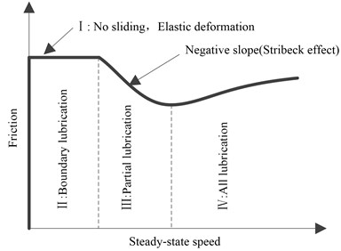
Rolling interface lubrication schematic for strip rolling is shown in Fig. 1. For different rolling speed, the relationship between friction force and speed can be divided into as follows: I region, that is a non-sliding zone, it has only elastic deformation; II boundary lubrication region, the speed is very low and has not enough lubricating oil to be sucked in, there is a solid and solid contact; III segmental lubrication region, although it has certain speed and lubricating oil can be inhaled, but it is not enough to separate the contact area; IV full lubrication area, the contact surface is separated by the oil film completely, its characteristic curve is shown in Fig. 2. Among them, the negative slope in part III is caused by the oil film gradual increase with speed increasing and friction decreasing. There has the Stribeck effect, namely there is negative damping phenomenon [12].
Fig. 1Rolling interface lubrication schematic
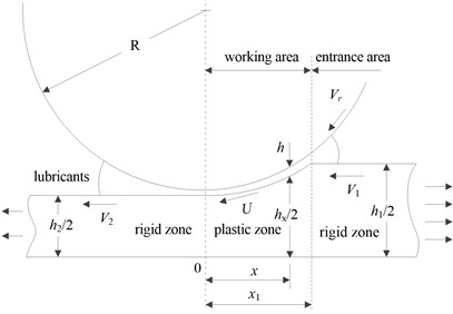
Fig. 2Interface friction characteristic curve
When the interface has a full fluid lubrication state, the lubricant fills cuneate cracks on the surface of the roller and rolled strip, and forms a thin oil film with a certain bearing capacity [13], so we set up the following two-dimensional Reynolds equation for steady and unsteady rolling process:
For wide strip (, is contact arc length, is the average thickness of strip entrance and exit), Eq. (3) can be simplified as one dimensional Reynolds equation as follows:
where, is the distance along the rolling direction, is the oil film thickness, is lubricating oil film pressure on the length of the wedge front the entrance of deformation area, is the average of the work roller surface circumferential velocity and strip steel velocity, is the dynamic viscosity of lubricant. For unsteady rolling process, the lubricant dynamic viscosity is not a constant, and it can be represented as (where, is the viscosity at temperature and normal pressure, is viscous pressure coefficient, is viscosity-temperature coefficient).
It can be seen from Eq. (4), the oil film pressure variation is composed by squeezing effect and dynamic pressure effect , and oil film thickness has no fluctuation in the steady rolling process. That is, the latter effect can only be considered but not the former. Then oil film pressure at any location is deduced as follows:
where, is work roller surface circumferential velocity, is the strip speed, , is the roll radius, the entrance lubrication layer thickness is (where, is viscosity compression coefficient, is the nip angle, is the rolled strip yield strength, is the strip steel back tension); The oil film shear stress at any location in deformation area is as follows:
where, is the fluid resistance coefficient, is the fluid lubrication coefficient, , are the neutral point coordinates, is the contact arc length, is the pass reduction rate. From the friction factor , and according to the Eq. (5) and Eq. (6), the average friction coefficient of the deformation zone can be approximately expressed as the follows:
where, is the rolled strip entry thickness, is the roller diameter. According to the rolling theory, only when is greater than the smallest friction coefficient , the rolling process can proceed steadily and there is Eq. (8):
So, in order to guarantee the rolling stability for a certain pass reduction rate , dynamic viscosity must have the maximum permission. Because the interface friction characteristics change is caused by the lubrication film thickness in the deformation area affected by the rolling speed and reduction rate, we deduce the average oil film thickness of deformation area . It can be seen the lube film thickness is proportional to the rolling speed and lubricant viscosity within a certain scope, it is inversely proportional to the contact angle and strip yield limit. At the same time, the thickness of the lubricating oil is also related to the roller material, such as cast iron roll is 30-40 % more than steel roll.
When the rolling interface is in the boundary or mixed friction state, there is ups and downs organization between a roller and strip, the lubrication film thickness of deformation area is very uneven, the entire contact area is composed by alternate boundary friction, liquid friction and dry friction area. And the total friction force can be represented as . where is the shear resistance within a very thin boundary lubrication layer, is the boundary friction zone area, is the shear resistance in large lubricating oil thickness, is the liquid friction zone area, is the shear resistance of direct contact with the surface area, is the dry friction area, is the sculpture resistance per unit, is the area to produce a sculpture function. Here, the segmental film elastohydrodynamic Reynolds equation should be adopted as Eq. (9) to the boundary friction [14]:
where, and are the nominal oil film thickness and the actual oil film thickness considering the effects of surface waviness. , and are the roughness effect coefficient respectively, the comprehensive roughness ( and are root mean square deviation of two surface roughness).
2.3. Influence analysis of rolling interface friction characteristics
The influencing factors of rolling interface friction characteristics are available very distinctly. In different extents of rolling deformation zone (such as the back-slip zone, adhesion area, stagnation zone, adhesive area and forward slip zone), the friction mechanism is different, and brings great difficulties to the theoretical calculation, so we often need to use experiments to study. In general, the influence factors of the rolling friction interface can be divided into: main influence factors, such as rolling temperature, lubricant viscosity, rolling speed and pass reduction rate, etc.; Secondary influence factors, such as the roll surface roughness, chemical composition, contact surface unit pressure, work roller diameter and vibration, etc.
2.3.1. Influence of temperature and speed
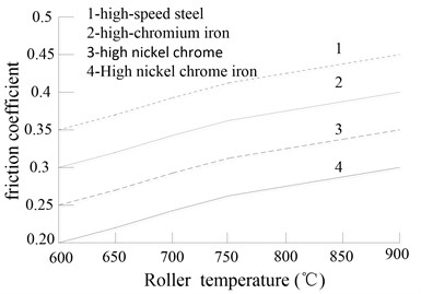
When the temperature is high, the microstructures and properties of metal will change, there will be surface bonding and the oxide film formation, so the rolled strip temperature influence on the friction coefficient is the largest. For low carbon steel, when the rolling temperature is above 700 ℃, the friction coefficient decreases with the increase of the rolling temperature and speed . And we often calculate it by empirical formula as follows:
or
where, is the roller surface roughness, is the carbon content of rolled strip, (0 2 m/s) or (2 3 m/s), friction coefficient variety test curve with the change of temperature is shown in Fig. 3.
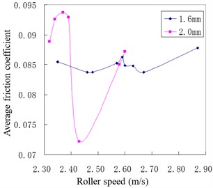
From the calculation of the experimental data, the F3 mill rolling friction coefficient is 0.01-0.1, which is at a mixture of fluid friction and boundary friction state. Based on field test data fitting, the relationship between the friction coefficient and speed is shown in Fig. 4 (1.6 mm and 2.0 mm are strip finishing thickness respectively). It can be seen that the curve was consistent with the Stribeck curve, namely, there is instability regions which friction fell sharply with the increase of rolling speed. And the friction coefficient is small, the regression equation between the friction coefficient and rolling speed is obtained as follows (corresponding to 2.0 mm strip curve):
Fig. 3Relationship between friction coefficient and strip temperature
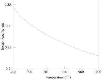
Fig. 4Relationship between friction coefficient and rolling speed
2.3.2. Oxide skin of roller and strip material influence analysis
The major influence of roller material on the friction coefficient is a carbon content, and each roller is different by carbide materials, such as the carbides in a high chromium cast iron roller is M7C3 (Hv2500), carbide in an infinite chilled cast iron roller is Fe3C (Hv1300), a high-speed steel roller has MC (Hv3000). Namely, the wear resistance of the high-speed steel roller is better than the one of the high chromium cast iron and infinite chilled cast iron roller, and it also has good red hardness to ensure it have high anti-wear ability under a high temperature. Their mechanical properties comparison is shown in Table 1. We also find it because the high-speed steel has the special microstructure, high thermal conductivity and high hardness carbides on the roller surface, it makes the friction coefficient increase by 3 %-5 % or greater. Its thermal cracking and anti-skid performance have obvious advantages.
Table 1Roller outer mechanical properties
Project | High-speed steel | High-chromium iron | High alloy chilled cast iron |
Carbide / % | 10-15 | 5-10 | |
Hardness / hsc | 70-90 | 70-80 | 75-85 |
Strength of extension / MPa | 700-1000 | 700-900 | 400-600 |
Compressive strength / MPa | 2500-3200 | 1700-2200 | 1900-2500 |
Fracture toughness / MPa·m-0.5 | 25-28 | 21-34 | 18–25 |
The oxide skin in hot rolling can be divided into: the thick primary oxide skin, the furnace life oxide skin, refractory oxide skin, secondary oxidation skin and red oxide, etc. Basic part of the iron oxide close to the metal surface is FeO, which accounts about 60-80 %. Fe3O4 and thin Fe2O3 in turn are outward. Due to the primary oxide skin, FeO is in a softening state, the friction coefficient is small, so it can cause slipping easily. The secondary oxidation skin is thin and hard, it can't completely fill the bumpy texture on the roller surface in the deformation zone, roller surface bump will be pressed into the surface of rolled piece to form the mechanical occlusion bond and even make the friction coefficient increase. In addition, the friction coefficient is affected by the carbon content in the roller or rolled piece, with the increase of carbon content in rolled piece, the friction coefficient has a significant reduction, such as the friction coefficient in rolling stainless steel is 1.3 times smaller than rolling carbon steel. According to the field test data and Eq. (7), the friction coefficient influences the relation curve with rolled piece type and roller material (roller temperature is also considered) fitted out for ordinary Carbon Steel (CS) and Steel Plate Atmospheric-Hot (SPA-H), and they are shown in Fig. 5 and Fig. 6 respectively. It can be seen from Fig. 5, with strip finishing, the thickness becomes smaller, the average friction coefficient is smaller, the rolling stability becomes worse, the mill vibration is easy to be produced. It can be seen from Fig. 6, the friction coefficient of high speed steel roller is the largest, that is, the use of a high-speed steel roll in certain conditions is beneficial to suppress the rolling mill vibration.
Fig. 5Rolled piece material influence on friction coefficient
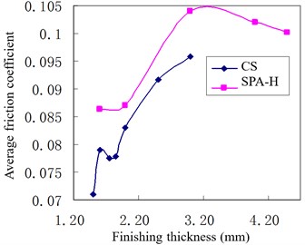
Fig. 6Roller material influence on friction coefficient
2.3.3. Lubricating oil influence
Hot rolling oil lubrication has a great influence on the rolling friction interface. The hot rolling friction coefficient of all kinds of additives is shown in Table 2. The kinematic viscosity of mineral oil 1 is 40 mm2·s-1 at 40 ℃. It can be seen that the friction dynamics of rolling interface can be improved if the emulsion liquid containing mineral oil is used. The kinematic viscosity of mineral oil 2 is 150mm2·s-1 at 40 ℃. In addition, the rolling oil lubrication performance will be different for a different roller material. Such as when the high alkaline organic acid salt rolling oil is used in a high-speed steel roller, due to the high alkaline organic metal salts has high alkaline Ca sulfonate (with reducing) as the main ingredients of hot rolling oil, it can prevent from the oxidation FeO of rolled piece transfer to the roller surface and turn into Fe3O4. So, it can inhibit the roller surface black oxidation generation, make the roller and surface oxidation film to modify, and can improve the roller surface friction coefficient.
Under the same lubrication condition, rolling force will increase with the reduction rate increase. The increase of rolling force will lead to roller flattening, the distortion of surface contact arc shape, curvature radius increase, elastic deformation in the contact region extension, reduction of hydrodynamic wedge angle of lubrication wedge forward area. It is advantageous for the lubricant into the deformation zone and increases the lubrication film thickness. So, with the increase of reduction rate, the deformation area lubrication dose increases and the friction coefficient reduces. For instance, when there is a vibration in the F3 mill, there is a sharp sound in the rolling interface sometimes, because with the increase of rolling speed, pumping oil increases, and the friction coefficient decreases. With the workpiece deformation increasing and deformation zone temperature rising, lubricating oil viscosity declines, oil film relative strength declines or breaks, the sharp noise sends out from the gap. Experiments showed that the roll with transverse cut has more than double lubricating layer thickness, because the transverse microscopic convex roughness has a “fence” role and can block lubricant extrusion.
Table 2Hot rolling friction coefficient of all kinds of additives
Additive | Friction coefficient | Additive | Friction coefficient |
Mineral oil 1 | 0.314 | P-c key compounds | 0.11 |
Mineral oil 2 | 0.219 | Vulcanized ester | 0.106 |
Rapeseed oil | 0.14 | Alkaline acid calcium | 0.1 |
Oleic acid | 0.126 | Calcium sulfonate | 0.161 |
Dimer acids | 0.1 | Oil soluble boric acid ester | 0.252 |
High viscosity resin | 0.106 |
3. Relation between interface friction and mill vibration
3.1. Influence of interface friction on mill vibration
Interface friction mainly affects rolling force, rolling process stability and mill structure stability. And then strengthens or weakens the rolling mill vibration strength [15]. According to experiment, the per-unit rolling force and its parameter effects (such as the friction coefficient) can be calculated as follows:
where, ( is the heat transfer coefficient, is the inlet temperature, is the average flow stress, is the interface relative speed), is the constant, is the strip steel average thickness. By Eq. (13), rolling force increases with the friction coefficient increase.
The rolling process stability is poorer in partial or full lubrication, and when the vertical vibration occurs in the roller, convex bodies have a slight contact and separation, the oil film thickness is thickening and thinning, the vertical contact stiffness of the whole system is also changing. When the work roller has a downward movement, the system stiffness increases; Conversely, it has soft spring characteristic. The lubrication state has great changes, and even causes bearing oil film rupture, then the influence of the squeezing effect in the Reynolds Eq. (4) cannot be ignored. That is, the vertical vibration is a typical nonlinear system caused by the friction force, the system is easy to produce the abnormal phenomenon such as parametric resonance. Under the full hydraulic lubrication, the oil film thickness (reflecting roll gap friction coefficient) has the greatest influence on rolling force . And the oil film thickness is mainly affected by the rolling speed , reduction rate and lubricant viscosity , then we can write as follows:
Rolling force fluctuation quantity can be expressed as:
Lubricant viscosity is the biggest influence factor on the oil film thickness, so its impact on rolling force can be represented as:
According to the rolling theory, rolling force is expressed as , and there is:
When reducing the reduction rate and increasing the lubricant viscosity , we have the same effect on the oil film thickness and lubrication state. Setting roll vertical vibration displacement equation as , there is:
After substituting Eq. (17) and Eq. (18) into Eq. (16), we find is negative. Namely, it increases stand vertical vibration system stiffness. Lubricating oil film in the roll gap for the vertical motion of the rolling mill system also play a role in damping, the greater is the lubrication film thickness, the lower is the friction coefficient, worse damping effect, reducing the friction influence on the rolling pressure, the closer is the relation between tension and rolling force, the worse system stability. When the rolling speed is greater than a certain value, the relation between the speed of rolling mill and the friction coefficient can be approximately expressed as the following formula:
where, , and are constants. From the Eq. (19), friction coefficient falls sharply with the increase of rolling speed, this friction force down can cause rolling mill negative damping and self-excited vibration easily, such as the Stribeck effect section in Fig. 2. Supposing the roll movement differential equation is expressed as , where, is the system damping, is a friction change slope with the speed (equivalent to the negative damping). When in negative damping critical conditions, i.e. , a roller likely produces self-excited chatter and is not stable. And when negative damping exceeds the critical condition , the rolling instability is divergent, rolling will not be able to maintain and even cause the equipment destruction.
When there is torsional vibration or horizontal vibration, the tangential and horizontal slide of mill roller and rolling piece will play a major role. Namely, the contact region with adhesion and sliding coexistence transits to full sliding. At this time, a neutral point will escape from the deformation zone periodically, rollers and rolled piece will produce the “slip-glue” skid phenomenon. It can make the interface friction coefficient to be changed at a dramatic and periodical state; The stability of the rolling process will decrease and induce vibration. By the Kaller theory, when the entire contact area from adhesion and sliding coexistence shift to full sliding, the friction (tangential force) of contact area reduces the maximum static friction force to dynamic friction, and the friction varies. Namely, the system produces a critical speed, and stick slip has a typical form of instability caused by friction. Namely, in the mixed film, lubrication is larger because of the effect of plastic fluid hydrodynamic lubrication, the interface shear stress decreases with the speed increase, and it can produce sudden acceleration and start an oscillation process, that is the self-excited vibration process. So, in order to control the rolling mill vibration, it is best to control the rolling lubrication thickness with or without lubrication.
3.2. Contrast test with rolling interface friction changing
From the foregoing analysis, the friction coefficient increases within a certain range and will contribute to the rolling stability, so we took the following measures for vibration comparison test by improving the interface friction state, such as open/close emulsion, high chromium cast iron/high speed steel roll and fine grinding/coarse grinding high chromium cast iron respectively,
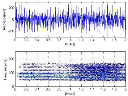
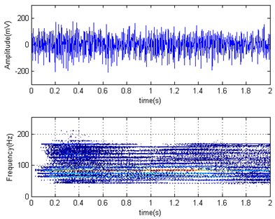
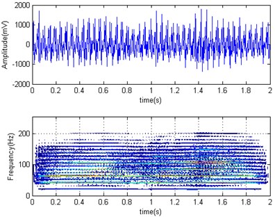
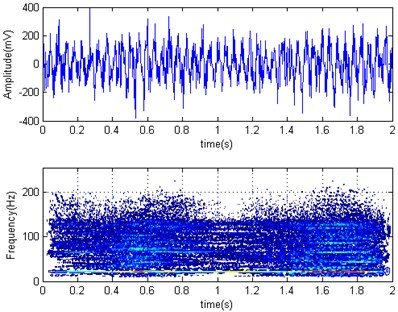
The CSP production line accepts the HYG-1 lubricating oil and in proportion by mixing device, lubricating oil and water are mixed evenly, we should prevent from oil and water emulsification completely. The horizontal acceleration time domain and Wigner-Ville distribution diagrams of F2 mill work roller were shown in Fig. 7 for rolling container plate at 2 mm finishing thickness when emulsion open (Fig. 7(a)) and close (Fig. 7(b)). It can be seen that the roller horizontal acceleration root mean square value is 87.30 mV (the unit is not converted) in emulsion open and 65.74 mV in emulsion closed, the amplitude decreased by 25 %. The rolling process and force parameter comparison is shown in Table 3 by changing the interface friction condition. It can be seen that although two strength parameters changed a little, but roller horizontal vibration acceleration amplitude decreased obviously after the emulsion close. From the frequency domain curve of emulsion close, work roller vibration energy is relatively concentrated, and shifts to a high frequency, which is beneficial to avoid system low order natural frequency and reduce the rolling mill vibration possibility. That is, the rolling interface has an improvement after the emulsion shut off, and there is a suppression effect on the rolling mill vibration.
Table 3Rolling process and force parameters comparison after interface friction condition change
Normal rolling | F2 high speed steel | F3 high speed steel | F3 roller coarse grinding | ||
F2, F4 emulsion open | F2, F4 emulsion close | ||||
F3 entrance width mm | 1143.07 | 1199.21 | 1199.4 | 1143.22 | 1143.25 |
F3 entry thickness mm | 12.099 | 12.354 | 12.372 | 11.318 | 11.537 |
Reduction rate % | 46.8 | 46.9 | 46.9 | 46.9 | 46.6 |
F3 inlet temperature ℃ | 982.84 | 991.73 | 996.53 | 995.86 | 1000.3 |
F3 exit temperature ℃ | 981.61 | 989.06 | 992.83 | 992.12 | 996.5 |
F3 contact arc length mm | 48.3 | 49.9 | 49.9 | 48.1 | 47.4 |
F3 work roller temperature ℃ | 52.84 | 38.02 | 53.36 | 47.86 | 46.83 |
F3 rolling force kn | 23994 | 26066 | 25368 | 22060 | 21341 |
F3 rolling torque kn∙m | 814.9 | 919.2 | 902.2 | 742.6 | 713.9 |
F3 largest rolling torque kn∙m | 14315.5 | 14725.2 | 14538.9 | 12963.6 | 12064.8 |
F3 rolling power kw | 5024 | 5508 | 5476 | 5056 | 5222 |
F3 backward tension N/mm2 | 69.15 | 74.08 | 74.19 | 64.69 | 65.95 |
F3 speed m/s | 2.32 | 2.37 | 2.4 | 2.73 | 2.83 |
F3 bending force kn | 1399.9 | 1400.2 | 970.3 | 1403.1 | 1400 |
F3 axial float mm | –38.55 | –33.13 | –100 | –88.27 | –72.12 |
F3 roller angular velocity round/sec | 0.96 | 0.9480 | 0.9600 | 1.0920 | 1.1320 |
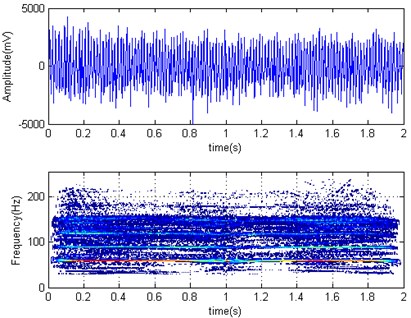
Fig. 7Horizontal acceleration time domain and Wigner-Ville distribution diagrams of F2 work roller
a)
b)
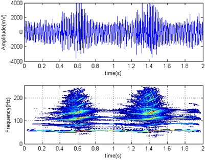
The horizontal acceleration of time domain and its Wigner-Ville distribution diagrams of F3 mill work roller were shown in Fig. 8 for rolling container plate at 2 mm finishing thickness with high chromium cast iron roller (Fig. 8(a)) and high speed steel roller (Fig. 8(b)). It can be seen the mean square root value is 519.9 mV and 116.21 mV respectively. That is, the roller acceleration amplitude decreased about 76 % after high speed steel adoption and the rolling force is also reduced. From their frequency domain graph, we can also see the energy distribution after using a high-speed steel roller, there is no obvious advantage frequency and vibration, it also can be felt at the scene obviously. So, there are obvious effects on the rolling mill vibration suppression by using high speed steel rollers.
Fig. 8Horizontal acceleration time domain and Wigner-Ville distribution diagrams of F3 work roller
a)
b)
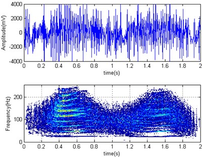
We also made a contrast test by normal and reduced rolling speed at field, the horizontal acceleration time domain and its Wigner-Ville distribution diagrams of F3 mill work roller were shown in Fig. 9 for rolling container plate at 1.6 mm finishing thickness with normal speed (Fig. 9(a)) and reduced (Fig. 9(b)) rolling speed. Its corresponding RMS values were 1283.7 mV and 1607 mV. Namely, the work roller acceleration amplitude increases about 20 % after reducing speed, vibration intensity has a tendency to increase after speed reducing. So, while it will be helpful to improve the friction coefficient, reduce strip strain rate and the rolling force with rolling speed reducing, but due to CSP technology restrictions, the pass rolling temperature decreases and the rolling force increases (which can be seen from Table 4) after reducing rolling speed. So, it is not desirable to suppress mill vibration by reducing the speed. Then the main factor affecting the rolling mill vibration intensity is the rolled piece material, such as the harder are materials under the same process, the greater is the rolling force and the more intense is vibration. The noticeable influence on the rolling mill vibration is the roll gap lubrication friction conditions for the same material conditions.
Fig. 9Horizontal acceleration time domain and Wigner-Ville distribution diagrams of F3 work roller
a)
b)
Table 4Rolling process force parameters at normal and slow speed
Normal rolling | Slow speed | Normal rolling | Slow speed | ||
Entrance width, mm | 1142.54 | 1142.84 | Rolling torque, KN∙m | 861.8 | 849.6 |
Entry thickness, mm | 10.546 | 10.543 | Maximal rolling torque, KN∙m | 11544.2 | 14095.7 |
Inlet temperature, ℃ | 971.53 | 956.52 | Rolling power, kw | 6567 | 5303 |
Outlet temperature, ℃ | 972.67 | 956.12 | Backward tension, N/mm2 | 60.24 | 60.25 |
Contact arc length, mm | 46.7 | 46.9 | Rolling speed, m/s | 2.87 | 2.35 |
Work roll temperature, ℃ | 38.66 | 46.56 | Roll bending force, KN | 1400 | 1401.4 |
Rolling force, KN | 25165 | 25494 | Axial float, mm | -35.01 | -28.58 |
Experiments of work roller surface coarse grinding were also carried out, the time domain horizontal acceleration and its Wigner-Ville distribution diagrams of F3 mill work roller were shown in Fig. 10 for rolling container plate at 2.0 mm finishing thickness with work roller coarse grinding. It can be found from the time-domain diagram, roller acceleration root mean square value is 1655.4 mV and has gained more than two times, so we think there is no suppression benefit for coarse grinding roller. And it can be seen from the scene feeling, F3 vibration feeling is more intense after coarse grinding.
Fig. 10Horizontal acceleration time domain and Wigner-Ville distribution diagrams of F3 work roller
4. Conclusions
Based on the fluid mechanics theory and rolling theory, we studied hot rolling friction interface dynamic characteristics under lubricated and non-lubricated condition respectively, the factors influence such as rolling speed, rolling load, roll material, rolling temperature and oil properties. The two-dimensional Reynolds equation was set up for steady and unsteady rolling process. Through the study of the interface friction influence on the rolling mill vibration, we found if the lubrication film thickness in the roll gap is greater, the friction coefficient is lower, its damping effect is worse, this will reduce the influence of friction on the rolling force, the closer is the relation between tension and rolling force, the worse is the system stability. When the rolling speed is greater than a certain value, the rolling interface friction coefficient falls sharply with the increase of rolling speed, this produces self-excited vibration by negative damping. The field contrast tests were carried out by changing rolling interface state, such as open/close emulsion, high chromium cast iron/high speed steel roller, fine/coarse grinding high chromium cast iron roller and normal/reduced speed. It can be found that the emulsion close and high speed steel roller adoption have the obvious effectiveness on rolling mill vibration suppression.
References
-
Furumoto H., Kanemori S., Hayashi K., Sako A., Hiura T., Tonaka H. Enhancing technologies of stabilization of mill vibration by mill stabilizing device in hot rolling. Procedia Engineering, Vol. 81, 2014, p. 102-107.
-
Kim Y., Chang-Wan K., Sung-Jin L., Park H. Experimental and numerical investigation of the vibration characteristics in a cold rolling mill using multibody dynamics. ISIJ International, Vol. 52, Issue 11, 2012, p. 2042-2047.
-
Kim Y., Park H., Soo L. S., Chang-Wan K. Development of a mathematical model for the prediction of vibration in a cold rolling mill including the driving system. ISIJ International, Vol. 52, Issue 6, 2012, p. 1135-1144.
-
Świątoniowski A., Gregorczyk R. Self-excited vibrations in four-high rolling mills caused by stochastic disturbance of friction conditions on the roll-roll contact surface. Mechanics and control, Vol. 29, Issue 3, 2010, p. 158-162.
-
Amer Y. A., El-Sayed A. T., El-Bahrawy F. T. Torsional vibration reduction for rolling mill's main drive system via negative velocity feedback under parametric excitation. Journal of Mechanical Science and Technology, Vol. 29, Issue 4, 2015, p. 1581-1589.
-
Fujita N., Kimura Y., Kobayashi K., Itoh K., Amanuma Y., Sodani Y. Dynamic control of lubrication characteristics in high speed tandem cold rolling. Journal of Materials Processing Technology, Vol. 229, 2016, p. 407-416.
-
Kijima H. An experimental investigation on the influence of lubrication on roughness transfer in skin-pass rolling of steel strip. Journal of Materials Processing Technology, Vol. 225, 2015, p. 1-8.
-
Schey J. A. Tribology in Metal Working: Friction, Lubrication and Wear, American Society for Metals, Ohio, 1983, p. 131-141.
-
Roberts W. L. Hot Rolling of Steel. CRC Press, Marcel Dekker Inc., New York, 1983.
-
Lee Wei-Pin Three-Dimensional Analysis in Rolling. The University of Michigan, 1992
-
Wilson W. R. D. Tribology in cold metal forming. Journal of Manufacturing Science and Engineering, Vol. 119, Issue 4, 1997, p. 695-698.
-
Dobrucki W., Bar A. Changes in roll-gap shape in the case of vibrations in a four-high rolling mill stand. Journal of Materials Processing Technology, Vol. 61, 1996, p. 328-337.
-
Geindreau C., Auriault J.-L. Investigation of the viscoplastic behavior of alloys in the semi-solid state by homogenization. Mechanics of Materials, Vol. 31, 1999, p. 535-551.
-
Hu Pei-Hua, Ehmann Kornel F. A dynamic model of the rolling process. Part I: Homogeneous model. International Journal of Machine Tools and Manufacture, Vol. 40, 2000, p. 1-19.
-
Munther Per A. The Effect of Material and Process Parameters on the Frictional Conditions in Hot Flat Rolling of Steels. University of Waterloo, 1997.
About this article

This research was supported by the Key Scientific Research Project of the Henan Province (No. 17A580003), Henan Polytechnic University Education Teaching Reform Research Projects (No. 2015JG034) and Colleges and Universities Focus on Soft Science Research Project Plan (No. 16A630049).
