Abstract
Theoretical investigation of the lateral and torsional vibrations of the hoisting cage in the cable-guided hoisting system caused by the eccentric load and the flexibility of the guiding cable is presented in this paper. The assumed modes method (AMM) is adopted to discretize the hoisting cable and two guiding cables, then Lagrange equations of the first kind are used to derive the equations of motion, while the geometric relationships between the hoisting cage and the cables are accounted for by the Lagrangian multiplier. Considering all the geometric matching conditions are approximately linear, the differential algebraic equations (DAEs) are transformed to the ordinary differential equations (ODEs). The dynamic responses of the hoisting cage are calculated, and especially the lateral displacements of the guiding cable and the constraints forces at the interfaces are obtained. Preload plays a vital role in affecting the cage vibration, thus, the effects of the total preload and the tension difference are analyzed. The numerical results indicate increasing the total preload can decrease the vibration displacements, while the tension difference has little impact on the vibration but can obviously change the constraint forces. In addition, the vibration displacements are directly proportional to the eccentric load, but less sensitive to the hoisting mass.
1. Introduction
Cables, due to their high strength and light weight, have been extensively applied to not only the hoisting system, such as mobile cranes [1], elevators [2] and mine hoisting [3], but also the other engineering including suspension bridges [4] and cable-driven parallel robots [5]. The cable-guided bucket hoisting system [6] is usually exerted to sink the deep vertical shaft, and then temporarily converted into one cable-guided cage hoisting system for transportation of equipment. In the typical cage hoisting system shown in Fig. 1(a), cables play an important role in guiding the cage when compared with the rail-guided hoisting system. The system is mainly composed of one hoisting cable, two guiding cables, a hoisting cage and a set of tensioning device, where the cage is held by the hoisting cable and supported by the two guiding cables. It is worth noting that the cage is connected to the guiding cables by four guide sleeves, and both ends of the guiding cables are completely restricted by the tensioning device. Unfortunately, cable is subjected to three-dimensional vibrations because of the external excitation and the cage undergoes the lateral vibration and even rotation for the high flexibility of the guiding cable. Therefore, it is necessary to predict the vibration displacements to avoid the danger of collision, and probe further into the relationship between the vibrations and the preload to improve the performance of the cable-guided cage hoisting system.
Many researchers have concentrated on the lateral vibrations of the hoisting cable or container for decades. Deb [7] studied the lateral vibration of a fixed-length string impacted by an elastic load at any point using. Fung et al. [8] analyzed the lateral vibration of an elevator cable characterized by time-varying length. Zhu and Xu [9] described the lateral behaviors for the stationary and moving hoisting cables with the initial displacement and presented the optimal suspension stiffness and damping coefficient. Kaczmarczyk and Ostachowicz [10, 11] investigated the lateral in-plane and out-of-plane responses of a catenary cable in the mine hoisting system and a compensation cable in a high-rise high-speed elevator. Zhu and Chen [12] conducted innovative experiments on a scaled elevator to validate the theoretical predictions for the uncontrolled and controlled lateral responses of a moving cable. Kimura et al. [13] performed a theoretical solution to the forced vibration of an elevator cable where both ends are excited and clarified the effect of the rate of change of cable length and the damping factor on the maximum lateral displacement. Bao et al. [14] theoretically and experimentally studied the nonlinear lateral vibration of a moving elevator cable and analyzed the passage through resonances by calculating the natural frequencies of the system. Ren and Zhu [15] presented the longitudinal and lateral vibrations of a moving two-cable one-rigid-body-car system, in which the rotation of the car is considered. For the spatial discretization of a cable, assumed modes method (AMM) [9, 14] and finite element method [16, 17] are commonly adopted. For the equation of motion, Lagrange’s equations [18, 19] or Hamilton’s principle can be selected.
However, until now little research has focused on the dynamic responses of the cable-guided hoisting system, especially the lateral and torsional vibrations of the hoisting cage caused by the eccentric load. In general, the guiding cables are simplified to a spring-mass system with a single degree of freedom and the high-order modes are omitted by the linear deformation assumption [6], thus, it is difficult to describe the whole vibration of the guiding cable. But in this paper, several challenging problems, such as the lateral displacement of the guiding cable and the constraint forces of the guide sleeves, are worked out. Considering the complicated boundary conditions between the hoisting cage and the guiding cables, the AMM and Lagrange’s equations with Lagrangian multipliers are combined to establish the vibration model.
Fig. 1Cable-guided cage hoisting system with eccentric load
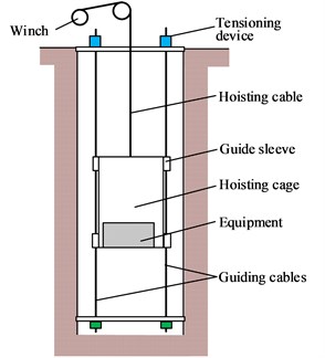
a) Cage hoisting system
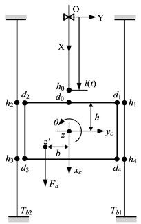
b) Schematic diagram
2. Lateral and torsional vibrations
For simplicity and without loss of generality, the cable-guided hoisting system (Fig. 1(a)) can be described as the vertically translating model shown in Fig. 1(b). This model is composed of one hoisting cable of length at time instant , two guiding cables of length and one cage attached to the lower end of the hoisting cable (). The cage of height 2 is supported by the two guiding cables through four guide sleeves (, 1-4). The hoisting cable has a vertically translating velocity and acceleration , where the over dot denotes time differentiation. In Fig. 1(b), the upper ends of two guiding cables are fixed to the derrick and the lower ends are constrained laterally and tensioned by the preloads and ; the displacements , and represent the longitudinal, lateral and torsional vibrations of the hoisting cage, respectively; and are the eccentric load and the offset distance.
2.1. Spatial discretization
With reference to Fig. 1(b), the kinetic energy associated with the longitudinal, lateral and torsional vibrations is:
where and are the mass per unit length of the hoisting cable and the guiding cable; and denote the longitudinal vibration of the hoisting cable and the lateral vibration of the guiding cables; and are the mass and moment of inertia of the hoisting cage, respectively.
The static tension in the cable is much larger than the vibratory one, as demonstrated in [15], thus the tension can be approximated by the static tension. The total potential energy of all the cables and the hoisting cage is:
where is the axial stiffness of the hoisting cable, and are the static tensions in the hoisting and guiding cables at position due to the gravitational acceleration g and given as:
The dissipated energy of the cables due to the damping is:
where and are the distributed damping coefficients of the hoisting and guiding cables, respectively.
For the hoisting cable and the guiding cables, the boundary conditions at both ends are:
The geometric matching condition at the interface between the hoisting cable and the hoisting cage is:
while the geometric matching conditions at four contact points between the hoisting cage and the guiding cables are:
Since the rotation of the cage is generally small, the approximations , and can be adopted. Therefore, Eq. (7) becomes:
For simplicity, herein two new dimensionless parameters and are introduced and the time-varying domain and the time-invariant for are both transformed to a time-invariant one [0, 1] for and . Hence, the dependent variable and become and , respectively. Further, the partial derivatives of with respect to and are related to those of with respect to and :
The similar derivations are presented as:
Accordingly, the boundary conditions in Eq. (5) become:
The lateral displacements can be approximated by expansions of a complete set of trial functions and expressed as:
where represents the number of included modes; are the generalized coordinates, in which 0, 1, 2; are the trial functions and should satisfy the homogeneous boundary conditions in Eq. (11), which can be expressed as:
Substituting Eqs. (1), (2) and (4) into Lagrange equations of the first kind [18]:
yields the equations of motion:
where is the vector of generalized coordinates; , , denote the displacements , and , respectively. It should be noted that these (33) generalized coordinates are not independent, however, the geometric matching conditions Eqs. (6) and (8) yield the holonomic constraints of the generalized coordinates, where is a vector including all the constraint conditions; is the Jacobian matrix of the constraint Eqs. (6) and (8), which is a 5×(33) matrix; and are called the Lagrangian multipliers [20], which denote the constraint forces between the hoisting cage and the three cables.
For notational convenience, a transformation matrix is introduced:
where is another sequence of the generalized coordinates. The matrices , , and are expressed as:
where:
2.2. DAEs to ODEs for solution
Considering the constraint conditions in Eqs. (6) and (8) are all linear algebraic equations, Eq. (15), a system of DAEs, could be transformed to ODEs. Thus, the second equation in Eq. (15) could be expressed in the form [21]:
where . Without loss of generality, suppose:
where must be a nonsingular 5×5 matrix, because its inverse matrix will be used subsequently. By Eqs. (6), (8) and (12), one can obtain:
It should be noted that the sequence of generalized coordinates is of great importance, because will be a singular matrix if rather than is selected in Eq. (15).
By Substituting Eq. (19) into Eq. (18), one has:
where a (32) vector, become the new generalized coordinates, which are linearly independent; is a (32) identity matrix.
Differentiating Eq. (20) twice yields:
Eq. (19) multiplied by Eq. (20) can yield . Substituting Eq. (21) into the first equation in Eq. (15), premultiplying by and applying yield:
with:
Eq. (22) can be solved by an ODE solver. can be assembled as:
3. Examples and discussion
The parameters of the cable-guided hoisting system used in the numerical simulation are as follows: 3 kg/m, 2.2 kg/m, 800 kg, 8 m, 870 kg·m2, 3.2×10⁷ N and 400 m. The damping coefficients are 30 kg/(m∙s) and 0.3 kg/(m∙s). The eccentric load and the offset distance are 1000 N and 1 m. The preloads in two guiding cables are 3×10⁴ N. The downward movement profile is plotted in Fig. 2, where the maximum velocity and acceleration are 5 m/s and 1 m/s2, respectively. The initial and final lengths of the hoisting cable are 50 m and 300 m, respectively. The external excitation is 0.01 m. The total simulation time is 60 s and the time step size is 0.01 s. The number of the modes is 50.
Fig. 2Downward movement profiles
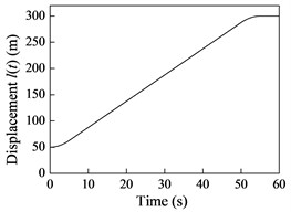
a) Displacement
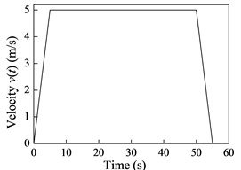
b) Velocity
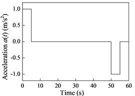
c) Acceleration
3.1. Dynamic responses
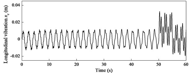
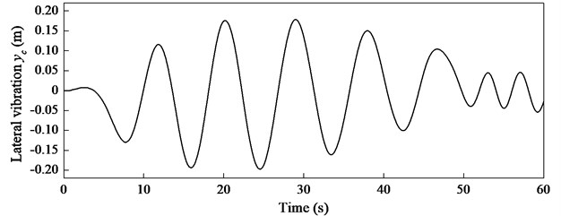
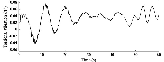
The longitudinal, lateral and torsional displacements of the hoisting cage can be obtained by solving Eq. (22) and the results are shown in Fig. 3. It is interesting to describe the shape of the guiding cable at different times. The lateral displacements of two guiding cables are identical because of the same preloads, thus, only one of two guiding cables is analyzed and the results at 18, 36 and 60 s are shown in Fig. 4.
Fig. 3The a) longitudinal, b) lateral and c) torsional displacements of the hoisting cage
a)
b)
c)
Fig. 4The lateral displacements of one guiding cable at different times
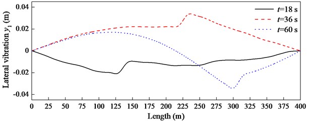
In Fig. 4, there is one short segment in each broken line, which is the position of the hoisting cage at that moment and results from the rotation of the cage. The length of the short segment is consistent with the height of the hoisting cage. It should be noted that the high-order modes of the guiding cable are considered, thus, the proposed method could present the whole vibration of the guiding cable.
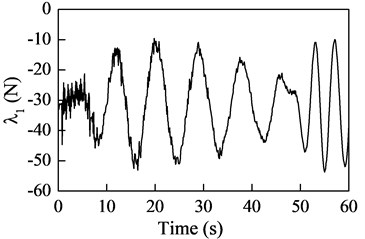
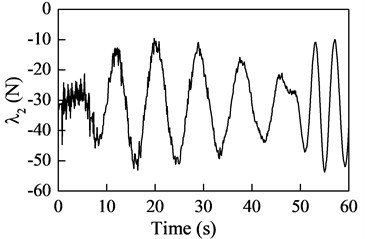
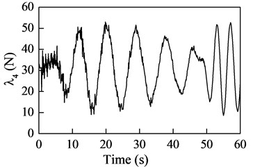
The Lagrangian multipliers can be obtained by substituting the solution Eq. (24) into Eq. (15), where denote the constraint forces between and . The results shown in Fig. 5 indicate and . However, and are approximately equal, because the height of the hoisting cage is too small when compared with the length of the guiding cable, but in opposite direction.
Fig. 5The constraint forces between the hoisting cage and two guiding cables

3.2. Effect of preload on system response
Preload in the guiding cable plays an important role in affecting the lateral and torsional vibrations, thus, here will analyze the effect from two aspects: total preload and tension difference.
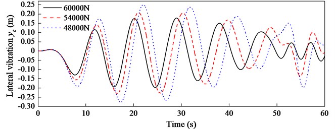
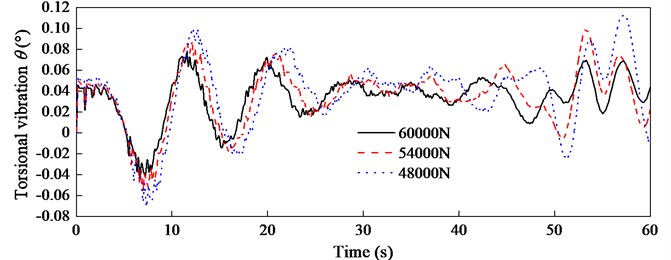
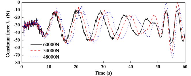
In case 1, the total preload 4.8×10⁴, 5.4×10⁴, 6×10⁴ N and . The effect on the lateral and torsional vibrations of the hoisting cage is shown in Fig. 6. It can be observed that the lateral and torsional displacements decrease with the increase of the total preload but the frequencies of both vibrations increase instead. The constraint force is shown in Fig. 7, which indicates that the frequency increases in the uniform velocity stage (first 50 s) and the amplitude decreases in the deceleration stage (last 10 s) as the total preload increases.
Fig. 6The a) lateral and b) torsional displacements with different total preloads
a)
b)
Fig. 7The constraint forces with different total preloads
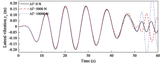
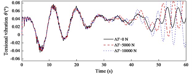
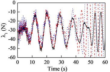
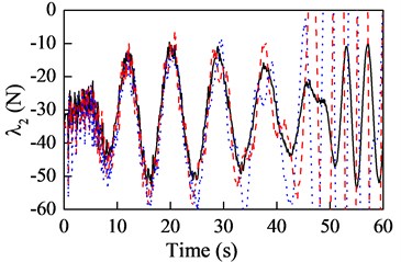
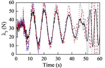
In case 2, the total preload is constant 6×10⁴ N and the tension difference 0, 5000, 10000 N. The effect of tension difference on the lateral and torsional vibrations of the hoisting cage is shown in Fig. 8. As can be seen in Fig. 8, in the uniform velocity stage the tension difference has little impact on the vibrations, but in the deceleration stage the displacements increase with the increase of the tension difference. Fig. 9 is presented to describe the effect on the constraint forces between the hoisting cage and two guiding cables. In Fig. 9, the constraint forces and decrease with the increase of the tension difference but and increase instead, which is reasonable because the lateral stiffness of the guiding cable increases with increase of the preload. In addition, the effect on the bottom ( and ) is more remarkable than the top ( and ).
Fig. 8The a) lateral and b) torsional displacements with different tension differences
a)
b)
Fig. 9The constraint forces with different tension differences
3.3. Effect of other parameters
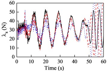
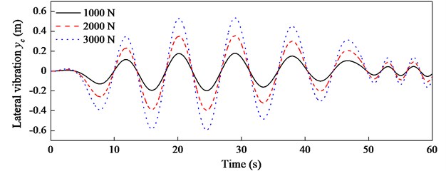
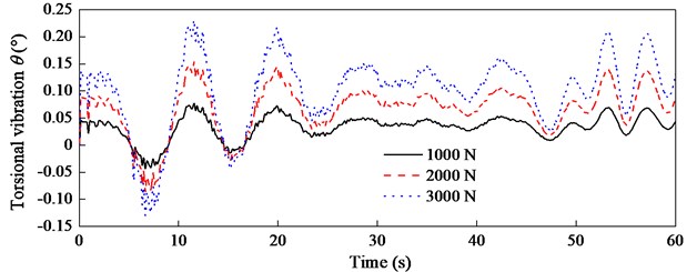
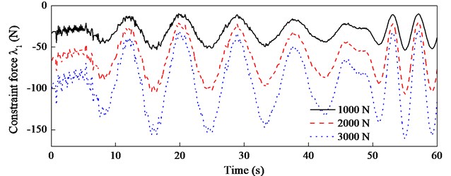
The system responses are affected by many factors besides the preload, here will concentrate on the effect of the eccentric load and the mass of the hoisting cage on the lateral and torsional vibrations of the hoisting cage. Let the eccentric load 1000, 2000, 3000 N and fix other parameters and the results are shown in Fig. 10. The lateral and torsional displacements are both directly proportional to the eccentric load, so is the constraint force, as shown in Fig. 11.
Fig. 10The a) lateral and b) torsional displacements with different eccentric loads
a)
b)
Fig. 11The constraint forces with different eccentric loads
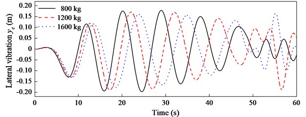
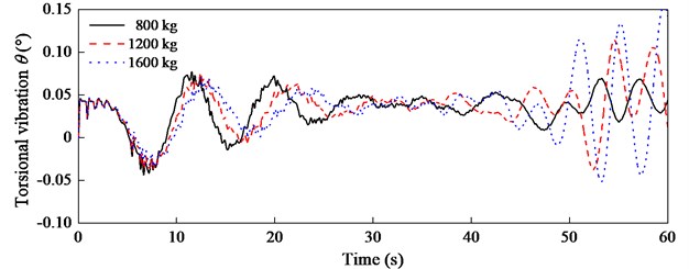
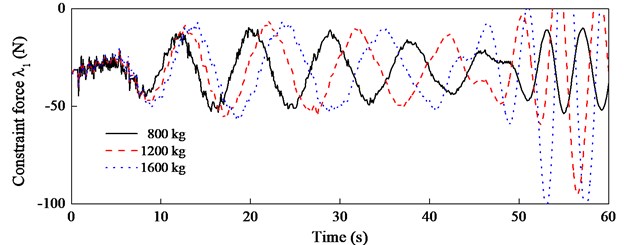
Considering the moment of inertia has a linear relation with the mass, the vibrations with 870, 1305, 1740 kg∙m2, corresponding to 800, 1200, 1600 kg are analyzed. As shown in Fig. 12(a), increasing the hoisting mass has little effect on the lateral vibration of the hoisting cage, but does decrease the frequency of vibration. In Fig. 12(b), increasing the hoisting mass has little impact on the amplitude and frequency of the torsional vibration in the uniform velocity stage, but decreases the amplitude in the deceleration stage. The effect on the constraint force is shown in Fig. 13. It can be observed from Fig. 13 that the amplitude remains the same and the frequency decreases with the increase of the hoisting mass in uniform velocity stage, but in the deceleration stage the amplitude increases.
Fig. 12The a) lateral and b) torsional displacements with different hoisting mass
a)
b)
Fig. 13The constraint forces with different hoisting mass
4. Conclusions
In this paper, the lateral and torsional vibrations of the hoisting cage induced by the eccentric load and the flexibility of the guiding cable are investigated. The cables are spatially discretized using the AMM and the equations of motion are established by Lagrange equations of the first kind. However, the introduction of the Lagrangian multiplier could deal with the complex geometric constraint conditions in the cable-guided hoisting system, but generates the DAEs. Therefore, the DAEs are transformed to the ODEs for solution, in which the permutation of the generalized coordinates is of great importance. The dynamic responses of the hoisting cage are calculated, and the lateral displacements of the guiding cable and the constraints forces at the interfaces are obtained. Because the high-order modes of the guiding cable are considered, the position and height of the hoisting cage is accurately presented in lateral vibration of the guiding cable. The theoretical model can not only predict the response of the cage to optimize the design of the hoistway, but also determine the suitable preload in the guiding cable.
Preload plays a vital role in the cable-guiding hoisting system, thus, the effects of the total preload and the tension difference on the cage vibration are analyzed. The numerical results indicate increasing the total preload can decrease the vibration displacements but increase the vibration frequency, while the tension difference has little impact on the vibrations but can obviously change the constraint forces. In addition, both the vibration displacements and the constraint forces are directly proportional to the eccentric load, but the displacements are less sensitive to the hoisting mass.
References
-
Qian S., Zi B., Zhang D., Zhang L. Kinematics and error analysis of cooperative cable parallel manipulators for multiple mobile cranes. International Journal of Mechanics and Materials in Design, Vol. 10, Issue 4, 2014, p. 395-409.
-
Arrasate X., Kaczmarczyk S., Almandoz G., Abete J. M., Isasa I. The modelling, simulation and experimental testing of the dynamic responses of an elevator system. Mechanical Systems and Signal Processing, Vol. 42, Issues 1-2, 2014, p. 258-282.
-
Wang D. G., Zhang D. K., Ge S. R. Effect of terminal mass on fretting and fatigue parameters of a hoisting rope during a lifting cycle in coal mine. Engineering Failure Analysis, Vol. 36, 2014, p. 407-422.
-
Wang Z. Q., Kang H. J., Sun C. S., Zhao Y. B., Yi Z. P. Modeling and parameter analysis of in-plane dynamics of a suspension bridge with transfer matrix method. Acta Mechanica, Vol. 225, Issue 12, 2014, p. 3423-3435.
-
Du J. L., Bao H., Cui C. Z. Stiffness and dexterous performances optimization of large workspace cable-driven parallel manipulators. Advanced Robotics, Vol. 28, Issue 3, 2014, p. 187-196.
-
Wang J. J., Cao G. H., Zhu Z. C., Wang Y. D., Peng W. H. Lateral response of cable-guided hoisting system with time-varying length: theoretical model and dynamics simulation verification. Proceedings of the Institution of Mechanical Engineers, Part C: Journal of Mechanical Engineering Science, 2015.
-
Deb K. K. Dynamics of a string and an elastic hammer. Journal of Sound and Vibration, Vol. 40, Issue 2, 1975, p. 243-248.
-
Fung R. F., Lin J. H., Yao C. M. Vibration analysis and suppression control of an elevator string actuated by a PM synchronous servo motor. Journal of Sound and Vibration, Vol. 206, Issue 3, 1997, p. 399-423.
-
Zhu W. D., Xu G. Y. Vibration of elevator cables with small bending stiffness. Journal of Sound and Vibration, Vol. 263, Issue 3, 2003, p. 679-699.
-
Kaczmarczyk S., Ostachowicz W. Transient vibration phenomena in deep mine hoisting cables. Part 1: Mathematical model. Journal of Sound and Vibration, Vol. 262, Issue 2, 2003, p. 219-244.
-
Kaczmarczyk S., Picton P. The prediction of nonlinear responses and active stiffness control of moving slender continua subjected to dynamic loadings in a vertical host structure. International Journal of Acoustics and Vibration, Vol. 18, Issue 1, 2013, p. 39-44.
-
Zhu W. D., Chen Y. Theoretical and experimental investigation of elevator cable dynamics and control. Journal of Vibration and Acoustics, Transactions of the ASME, Vol. 128, Issue 1, 2006, p. 66-78.
-
Kimura H., Ito H., Fujita Y., Nakagawa T. Forced vibration analysis of an elevator rope with both ends moving. Journal of Vibration and Acoustics, Vol. 129, 2007, p. 471-477.
-
Bao J. H., Zhang P., Zhu C. M., Sun W. Transverse vibration of flexible hoisting rope with time-varying length. Journal of Mechanical Science and Technology, Vol. 28, Issue 2, 2014, p. 457-466.
-
Ren H., Zhu W. D. An accurate spatial discretization and substructure method with application to moving elevator cable-car systems. Part II: Application. Journal of Vibration and Acoustics, Transactions of the ASME, Vol. 135, Issue 5, 2013, p. 51037.
-
Wang P. H., Fung R. F., Lee M. J. Finite element analysis of a three-dimensional underwater cable with time-dependent length. Journal of Sound and Vibration, Vol. 209, Issue 2, 1998, p. 223-249.
-
Du J. L., Cui C. Z., Bao H., Qiu Y. Y. Dynamic analysis of cable-driven parallel manipulators using a variable length finite element. Journal of Computational and Nonlinear Dynamics, Vol. 10, Issue 1, 2015, p. 11013.
-
Dvorak R., Freistetter F. Chaos and Stability in Planetary Systems. Springer-Verlag, Berlin, Germany, 2005.
-
Zhu W. D., Ren H. An accurate spatial discretization and substructure method with application to moving elevator cable-car systems. Part I: Methodology. Journal of Vibration and Acoustics, Transactions of the ASME, Vol. 135, Issue 5, 2013, p. 051036.
-
Lanczos C. The Variational Principles of Mechanics. Dover Publications, New York, 1986.
-
Ilchmann A., Reis T. Surveys in Differential-Algebraic Equations II. Springer-Verlag, Berlin, Germany, 2015.
Cited by
About this article

This work is supported by the National Natural Science Foundation of China (51475456), the National Key Basic Research Program of China (2014CB049401), the Fundamental Research Funds for the Central Universities (2013QNB12), and the Priority Academic Program Development of Jiangsu Higher Education Institutions (PAPD).
Jinjie Wang derived the equations of motion of the cable-guided hoisting system, discussed the dynamic responses and drew the conclusions. Guohua Cao proposed the idea of the paper, transformed the differential algebraic equations to the ordinary differential equations (ODEs) and improved the conclusions from dynamic responses. Zhencai Zhu analyzed the previous literature, summarized the “Introduction”. Jinjie Wang, Guohua Cao and Zhencai Zhu drafted the manuscript together. Weihong Peng wrote the computing programmer, obtained the solution and improved the language of the revision. Jishun Li studied the effects of all parameters on the system responses. All authors have corrected and approved the final manuscript.
