Abstract
A high-energy liquid-jet hammer with specially designed backward stroke end buffer structure was investigated computationally. Computational Fluid Dynamics (CFD) with the technique of dynamic and sliding meshes method was employed in this study. Results indicated that each of the geometric parameter of the buffer structure had a significant effect on the backward impacting energy of the impact body and brought a maximum of 49.8 % of backward impacting energy reduction. Experimental tests based on the non-contact measuring method were conducted to verify the simulation results, by which the accuracy and reliability of this CFD simulation method was proved. In addition, the high-energy liquid-jet hammer worked well with the optimal parameters of the buffer structure in bench testing and reached high penetration rate in a drilled borehole.
1. Introduction
Hard rock drilling is becoming increasingly important due to both the progress on the use of geothermal heat as a new energy source and the development of new unconventional gas fields [1]. Down-the-hole (DTH) hammer drilling method is considered as one of the best approaches for hard rock drilling [2], which can convert a portion of the power resident in the drilling fluid into mechanical impacts directly upon the drill bit, thus driving the drill bit into the formation. This percussive action has the effect of increasing the instantaneous weight on bit (WOB), even though the mean WOB may be kept at typical or below than typical levels for drilling. The end results of this action are that the penetration rate of the drill bit is increased, the drill bit life is increased, and the unplanned borehole deviation is decreased [3]. DTH hammer drilling with mud instead of air as drilling fluid, is a competitive method for production of drill-holes. The use of mud eliminates many of the disadvantages connected with air-driven DTH hammers. One of the main differences is the capability to drill deep holes even in water rich environment. Low energy consumption is another benefit that has made the method popular in exploration core drilling and oil, gas drilling. Also, working environment is improved because dust is eliminated and the atmosphere is oil-free and without grease residues [4, 5].
The liquid-jet hammer is a type of DTH hammer driven by mud and has been widely applied in exploration core drilling. It has also played an important role in the No.1 hole of the Project of China Continental Scientific Drilling (CCSD) from 2001 to 2005 [6]. Numbers of field tests show that the drilling efficiency by the use of liquid-jet hammer in hard rock formations can be improved more than 50 % on average compared with the conventional rotary drilling method [7]. In addition, the work performance of the liquid-jet hammer will not be affected by the borehole depth due to its working principles [8]. It has made successful application by the use of YSC178 liquid-jet hammer in deep hole drilling at the depth of 6322 m in Xinjiang Tahe Industrial Zone in China and the field tests have proven that the liquid-jet hammer can increase the rate of penetration (ROP) by more than 120 % in deep borehole drilling project [9]. However, to date there is no drilling tool available on the market, which uses mud hammer drilling methods and can increase ROP by multiples like an air hammer drilling does.
In the liquid-jet hammer, a bi-stable fluidic amplifier, rather than a sliding or rotating valve, is used to control the reciprocating movement of the impact body. Because of the absence of moving parts in the bi-stable fluidic amplifier, a liquid-jet hammer can work more reliably in a drilling hole than tools with a moving mechanical valve, especially in the extreme situations of high temperature and high pressure, where mechanical valves have difficulties in coping with the complex and harsh working environment [10]. Comparing with a traditional mud hammer tool based on the switching movement of a mechanical valve, there seems to be much more room of performance improvement for a liquid-jet hammer, and the development of a high energy liquid-jet hammer is incredibly significant.
The ROP in the DTH hammer drilling is closely related to the impacting energy of hammers. Improving the flow velocity at the supply jet of the bi-stable fluidic amplifier is a effective way to reach higher impacting energy for the liquid hammer [11]. However, technical difficulties associated with erosion and wear have slowed down the improvement and made putting this idea into practice difficult. This situation began to change until resent years when experiments show that the use of cemented carbide materials to develop the bi-stable fluidic amplifier can effectively avoid premature failure of the bi-stable fluidic amplifiers in the hammers caused by rapid erosion or wear. Nevertheless, the cemented carbide is a kind of brittle composite material which breaks easily under powerful impact loads. While the impact body reaches its rear stroke end position with considerable energy, it will cause impact of collision on the end. In order to avoid the damage of the bi-stable fluidic amplifier caused by the backward impact [12], it is necessary to design a suitable buffer structure for the liquid-jet hammer to buffer the backward impact, and the buffer structure must be simple and reliable due to the complex and volatile environment in the drilling boreholes. Zhang et al. has successfully made cylindrical helical springs applied to buffer the backward impact of piston, however adding wearing parts to the system and the springs are easy to fail for the rapid erosion and fatigue failure [13]. Considering the damping devices widely used in a hydraulic system, a new buffer structure is proposed to buffer the backward impact by using the damping force of liquid. In this paper, the parametric design of the buffer structure was investigated and experimental tests were conducted to validate the effectiveness and feasibility of the specially designed buffer structure.
2. Description of the liquid-jet hammer and the buffer structure
As shown in Fig. 1, a liquid-jet hammer mainly consists of a bi-stable fluidic amplifier and an actuator which is composed of a cylinder, a piston and a mass block. The piston divides the cavity of the cylinder into two chambers: the front chamber and the rear chamber. The piston and the mass block are connected to each other to form an impact body.
When the liquid-jet hammer works normally, the high pressure liquid enters the bi-stable fluidic amplifier through the supply nozzle and is turned into a jet with relatively large kinetic energy in the interaction region, because of the transversal pressure difference produced by the unbalance of entrainment of the surrounding liquid, the jet will deflect to one side of the adjacent attachment wall and enters one of the chamber of the cylinder through the output channel, thus pushing the impact body to move forth or back. When the impact body reaches one of its stroke ends, a large pressure pulsation charged with high pressure energy will be produced in the output channel caused by sudden stop of the impact body. Part of the pressure pulsation propagates along the feedback loop to the outlet of the control nozzle on the deflected jet side, where the pressure energy is converted into kinetic energy of liquid, exerting a transverse force and flow momentum on the supply jet, thus triggering the supply jet to detach from the initially attached side wall and attach onto the other side. This detachment and attachment process continues, leading to the periodic oscillation and the reciprocating movement of the impact body, thereby generating persistent periodic impact force acting on the drill bit [14].
Fig. 1A schematic of the liquid-jet hammer. 1: Top tie-in; 2: disc springs; 3: Seal cover; 4: Bi-stable fluidic amplifier; 5: Cylinder; 6: Upper sleeve; 7: Piston; 8: Cylinder lid; 9: Mid tie-in; 10: Lower sleeve; 11: mass block; 12: Drill bit retainer semi-ring; 13: Internal splined sleeve; 14: Drill bit
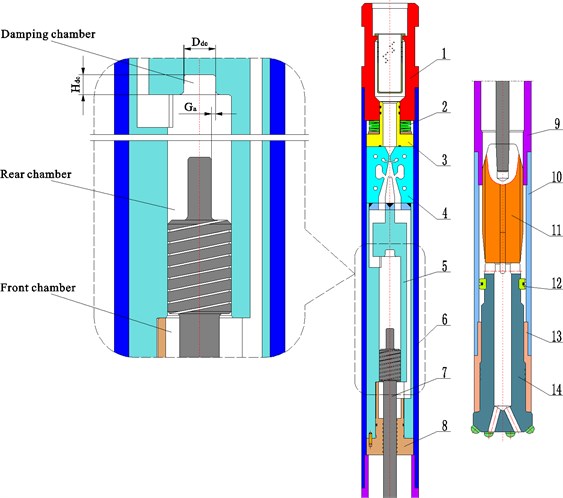
The buffer structure (shown in Fig. 1) consisting of the rear piston rod and the damping chamber is arranged on the upper part of the cylinder and the geometric parameters of the buffer structure include (diameter of the damping chamber), (size of the annular gap between the rear piston rod outer wall and the inner damping chamber wall) and (depth of the damping chamber). When the impact body moves up and is about to reach its rear stroke end position, the piston is dampened by the rear piston rod cutting off the damping chamber so that the piston is retarded before it lands in its rear stroke end position and will therefore not tend to rebound with high velocity. The whole buffering process is divided into three stages, which are local pressure loss caused by across sectional area shrinking, sharp edge throttling and aperture throttling [15].
3. Governing equations for the movement of the impact body
Ignoring frictional and buoyant forces, the impact body is driven by the pressure difference between the rear and front surfaces of the piston and the gravity force. The net force acting on the impact body can be calculated from:
where is the piston section area, is the front piston rod section area, is the rear piston rod section area, is the rear chamber liquid pressure, is the front chamber liquid pressure, is the damping chamber liquid pressure, is the mass of the impact body, is the acceleration of gravity, 9.81 m/s2.
The acceleration a of the impact body is presented as follows:
The initial velocity of rebound is calculated from:
where is the impacting velocity of the impact body, is the coefficient of rebound.
The acceleration is considered to be a constant in each time step, respectively. In each time step the displacement of the impact body can be written as:
where and 1 represent the present and immediate next numerical time step value.
4. Numerical simulation
By means of computational fluid dynamics (CFD) technology, Chen et al. investigated the flow field of the fluidic amplifier in a liquid-jet hammer [16]. With the help of CFD dynamic analysis, the velocity field of the flow domain in a liquid-jet hammer was investigated in detail, and the process of the attachment and switch of the supply jet was numerically modeled. Peng et al. investigated the effect of geometric parameters of the bi-stable fluidic amplifier in the liquid-jet hammer on its threshold flow velocity by means of dynamic CFD analysis and verified their theoretical prediction by an experimental test [10]. By using simplified 2D computation CFD Models, Wang et al. [17] investigated the effect of varying structural parameters on the flow characteristics of the fluidic amplifier. By the use of 3D CFD computational models, He et al. [18] calculated the pressure drop in a fluidic jet oscillator which is similar to a fluidic amplifier in working principles.
While the present study is intended to computationally investigate the buffering performance on 14 liquid-jet hammer models, among which there were 13 liquid-jet hammers having different geometric parameters of the buffer structure and another one without setting buffer structure as a comparison. These 13 models are divided into three groups, only one design parameter is variable in each group. In these different computational domains, the flow field of the liquid-jet hammer which contains the flow field of a bi-stable fluidic amplifier, the discharge channels, the front and rear chambers of the cylinder and the connecting passages between the bi-stable fluidic amplifier and the cylinder were kept the same. In addition, the stroke of all the liquid-jet hammers simulated is 140 mm and the mass of the impact body is 4 kg.
Table 1The geometric parameters of the buffer structure in the liquid-jet hammers simulated
/ mm | / mm | / mm |
6 | 0.05 | 2 |
8 | 0.10 | 4 |
10 | 0.15 | 6 |
12 | 0.20 | 8 |
14 | 0.25 | 10 |
The present computational model is based on a 3D geometry, Fig. 2 shows the CFD mesh of one of the 14 models of computational domains used in this study. A pentahedron mesh can fit into small acute angles in the geometry and a hexahedral mesh is known to be less diffusive compared to other types of meshes like tetrahedral [19]. In this mesh there are totally 122,098 cells among which 396 cells are pentahedron and the rest are hexahedral. All the grids used were generated by Altair Hypermesh software. Each grid serves as a starting volume mesh needed to use the dynamic mesh model.
There are two stages for the simulation of a liquid-jet hammer, the steady computation and the transient computation. The results of steady computation are used as the initial conditions for the transient computation. In the simulation with steady computation, flow simulation was carried out using a 3D single-precision steady-state segregated solver. In this method, the governing Navier-Stokes equations are solved sequentially using iterative methods until defined values of convergence are met. In this stage, a velocity inlet boundary condition was applied at the inlet of the fluidic amplifier, and the outlets of the liquid-jet hammer which are connected with the discharge channels of the fluidic amplifier were defined as pressure outlet boundary conditions and were set to atmospheric pressure. Water was selected as the fluid material for the fluid zone of the liquid-jet hammer. The initial input flow rates of all models were 200 L/min and the cross section areas at the inlet of the fluidic amplifiers were 207.6 mm2, therefore, the initial inlet velocity of the liquid-jet hammer was 16.04 m/s. Besides, the no slip boundary condition was used at other boundaries.
Fig. 2CFD mesh of a liquid-jet hammer
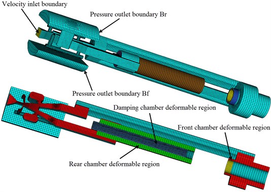
Fig. 3Sliding and deforming meshes
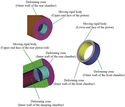
In the stage of a transient computation, eight dynamic mesh zones were defined, as shown in Fig. 3. The outer walls of the rear and front chambers, the inner walls of the rear and front chambers and the inner wall of damping chamber were defined as deforming zones, respectively. The upper and lower end face of the piston and the upper end face of the rear piston rod were defined as moving rigid body.
Motion of the piston and the piston rod faces changes the flow zones immediately nearby them. Therefore, the computational grid should be updated. In the simulations, dynamic layering method provided by Fluent was used to update the mesh in the deforming regions subjected to the boundary motion caused by piston and rear piston rod movement. The update of the volume mesh in dynamic mesh modeling is handled automatically at each time step based on the new positions of the piston and the rear piston rod.
The rear piston rod face has a reciprocating motion in the damping chamber of the buffer structure while the liquid-jet hammer is in operation. Therefore, the moving boundary of the rear piston rod face is an internal zone. Cells on the damping chamber zone and the rear cylinder chamber zone are of different cell layer heights. In order to use dynamic layering on cells adjacent to the moving wall of rear piston rod face that do not span from boundary to boundary, these cells involved in the dynamic layering must be separated and use the sliding interfaces capability in Fluent to transit from the deforming cells to the adjacent non-deforming cells. For a moving interior face, the zones must be separated such that they are either expanding or collapsing on the same side. No one zone can consist of both expanding and collapsing layers.
In the sliding mesh technique two or more cell zones are used. Each cell zone is bounded by at least one “interface zone” where it meets the opposing cell zone. The interface zones of adjacent cell zones are associated with one another to form a “grid interface”. The two cell zones will move relative to each other along the grid interface. As shown in Fig. 3, The inner wall of the rear chamber and the inner wall of the damping chamber were defined as interface zones, respectively.
5. Simulation results
14 models were investigated computationally by CFD simulations and a large amount of information is obtained. The buffer performance of the buffer structure in an SC86H liquid-jet hammer can be predicted using the computational information and whether the geometric parameters of a buffer structure make an SC86H liquid-jet hammer work or not can also be known. Shown in Fig. 4, are a group of typical sectional contours of the flow velocity magnitudes of a liquid-jet hammer at four instants when it works normally.
Fig. 4Typical sectional contours of flow velocity (m/s) at four instants when the liquid-jet hammer with buffer structure works: a) At the midway of backward movement of the impact body; b) At the end of backward movement of the impact body; c) At the midway of forward movement of the impact body; d) At the end of forward movement of the impact body
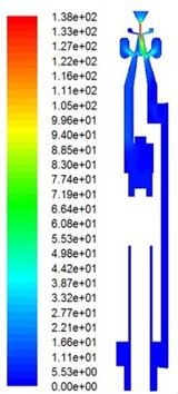
a)
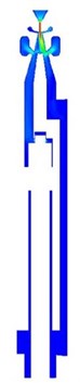
b)
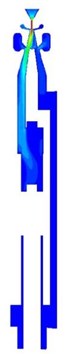
c)
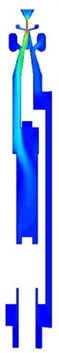
d)
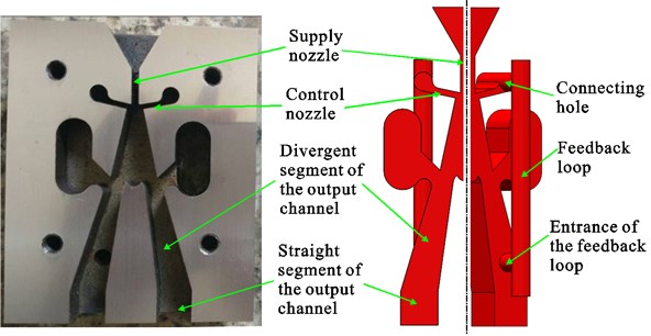
The buffer structure is mainly applied to reduce the backward impacting energy of the impact body so as to minimize damages to the bi-stable fluidic amplifier. As the backward impacting energy is proportional to the square of the backward impacting velocity, the backward impacting velocities of the impacting bodies were calculated by the simulation. Theoretically, if the value of backward impacting velocity is near 0, almost all the impacting energy will be absorbed by the buffer structure and there will be little damage to the fluidic amplifier caused by impacting. However, previous studies [10, 14] have indicated that the backward impacting velocity of the impact body should be limited in a certain scope, for the supply jet switching mechanism of the fluidic amplifier in the liquid-jet hammer is special. As shown in Fig. 5, in a fluidic amplifier, a feedback loop has been designed between the control nozzle and the output channel on each side. When the impact body reaches one of its stopping ends, a large pressure pulsation is produced in the cylinder chamber charged with high pressure liquid. Part of the pressure pulsation propagates along the feedback loop on the side of the attached supply jet. As the pressure energy reaches the control nozzle, it converts into kinetic energy of liquid and the flow velocity at the control nozzle increases significantly, forming a liquid jet to push the supply jet to switch to the other side. The pressure pulsation is mainly composed of pressure energy caused by sudden stop of the impact body and its value of the pressure pulsation is in positive correlation with the impacting velocity. Therefore, if the backward impacting velocity decreased greatly, the pressure pulsation as was mentioned will not be large enough to trigger the supply jet to the other side and the liquid-jet hammer will not work. In order to analyze the effect of the velocity at the control nozzle on the switching process, the velocity is monitored in the cross sections of the control nozzle.
Simulation results concluded that the forward and the backward impacting energy of the SC86H liquid-jet hammer without setting buffer structure are 131.22 J and 28.58 J, respectively, and its impacting frequency of the liquid-jet hammer is 15.5 Hz.
Fig. 5Configuration of the bi-stable fluidic amplifier in the liquid-jet hammer. Left – amplifier with cover plate removed; right – solution domains of amplifier
5.1. The effect of the geometric parameters of the buffer structure on impacting energy and impacting frequency of the impact body
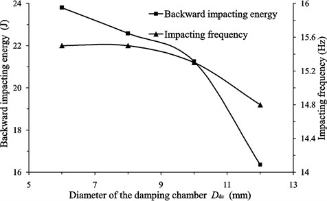
As shown in Fig. 6(a), the backward impacting energy decreases with the increasing of the diameter of the damping chamber. As the damping chamber diameter changes from 6 mm to 12 mm the backward impacting energy decreases to 16.36 J. Comparing to the value of 28.58 J that the impact body moves without buffering, poses 42.8 % of energy reduction. However, when the damping chamber diameter changes to 14 mm, the liquid-jet hammer cannot work.
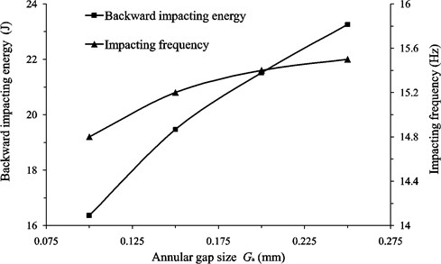
As shown in Fig. 6(b), the backward impacting energy increases with the increasing of the size of the annular gap. However, when the annular gap size is less than 0.1 mm the liquid-jet hammer will not work. As the annular gap size varies from 0.1 mm to 0.25 mm, the minimum and the maximum of the backward impacting energy are 16.36 J and 23.26 J, respectively. When the size of the annular gap increases beyond 0.25 mm, the buffer structure is likely to have little effect for the liquid-jet hammer.
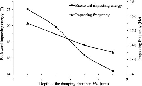
Fig. 6(c) indicates that with the increase of the depth of the damping chamber the backward impacting energy increases. When the depth of the damping chamber is greater than 8 mm, the liquid-jet hammer will not work and the minimum of the backward impacting energy is 14.36 J, meaning 49.8 % of energy reduction.
As shown in Fig. 6, it can be concluded that the impacting frequency has the same trend with the backward impacting energy as the geometric parameters of the buffer structure varies. Nevertheless, the value of variation of the frequency is less than 1 Hz which is very small and can be ignored. Meanwhile, the forward impacting energy is kept the same of 131.22 J. Therefore, the setting of the buffer structure is reasonable and causes little energy consumption.
Fig. 6The effect of the geometric parameters of the buffer structure on the backward impacting energy and the impacting frequency of the liquid-jet hammers: Geometric parameters include a) Diameter of the damping chamber Ddc; b) Annular gap size Ga; c) Depth of the damping chamber Hdc
a)
b)
c)
5.2. Analysis of simulation results on buffering process of the impact body with the action of buffer structure
As shown in Fig. 7, at the beginning of the buffering process, the acceleration of the impact body changes sharply with displacement varying, which is mainly due to the sudden local pressure loss and sharp edge throttling. The maximum of the acceleration in this process is remarkably large, and it is clear to find that as the annular gap size increases the maximum value of the acceleration approximately decreases linearly. In the next stage of the buffering process, the acceleration changes relatively smoothly, as the aperture throttling action is relatively steady and changes little. Obviously, under different annular gap sizes, the variation tendencies of the acceleration are similar though the magnitudes are different.
Fig. 7The curves of the buffering process under different annular gap sizes
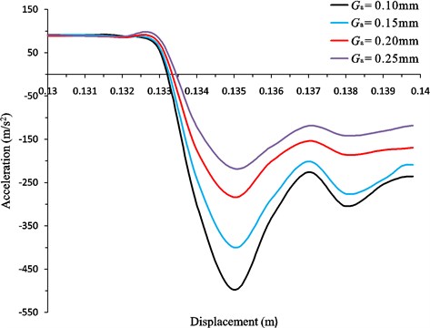
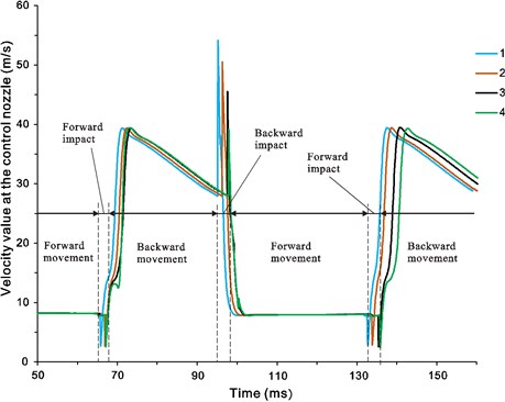
Fig. 8The curves of the velocity at the control nozzle. Corresponding to the curves 1-4 the depth of the damping chamber is 2-8 mm respectively
5.3. Analysis of simulation results on switching process of the bi-stable fluidic amplifier
In order to analyze the effect of the depth of the damping chamber on the switching process, average velocity was monitored at the cross section of one of the control nozzles (corresponding to the rear chamber). Simulation results showed that once the depth of damping chamber is not larger than 8 mm, the peak velocity at the control nozzle is great enough to make the supply jet switch. As shown in Fig. 8, the peak velocity at the control nozzle decreases from 53.8 m/s to 39.4 m/s as the depth of the damping chamber increases from 2 mm to 8 mm. Therefore, the value of 39.4 m/s can be seen as the threshold of the peak velocity at the control nozzle, when peak velocity at the control nozzle is lower than the threshold value, the supply jet will not switch to the other side attachment wall.
6. Experimental validation
It can be concluded by the CFD simulation results that the optimal design of the geometric parameters of the buffer structure consists the diameter of the damping chamber, annular gap size and the depth of the damping chamber with the values of 12 mm, 0.1 mm, 6 mm, respectively. The liquid-jet hammer was designed and manufactured with the optimal geometric parameters of the buffer structure and the experimental tests had been subsequently conducted in order to validate the working feasibility of the liquid-jet hammer with setting the buffer structure and the consistency between the experiments and the simulations.
In order to validate the working feasibility of the liquid-jet hammer with setting the buffer structure, as shown in Fig. 9, the complete prototype of the liquid-jet hammer was use to drill on granite blocks with 140-160 MPa compressive strengths. Measurements of the penetration rate during this drilling were performed, with the aim to mainly compare the effectiveness of conventional rotary drilling. The results of the vertical directed drilling were summarized in Table 2. Experimental tests showed that the average ROP of drilling by the use of liquid-jet hammer was 5.2 m/h, which was 5.5 times faster than rotary drilling with a roller cone bit. Moreover, the liquid-jet hammer can work more than 30 h without failure while the impact body striking an anvil continuously in the bench testing. Therefore, the buffer structure for the liquid-jet hammer was suitable and effective, keeping the bi-stable fluidic amplifier in safe condition without damage of collision.
Table 2Summarized results from vertical directed drilling with SC86H liquid-jet hammer
Hammer | SC86H liquid-jet hammer |
Bit | ø95 mm |
Rock | Granite, Compressive strength 130-150 MPa |
Drilling direction | Vertical |
Piston frequency | 14-16 Hz |
Volume flow rate | 200 L/min |
WOB | 0.6 t |
Average ROP | 5.2 m/h |
Fig. 9Experimental prototype of the liquid-jet hammer: a) process of drilling by the use of the liquid-jet hammer; b) structure of the liquid-jet hammer manufactured
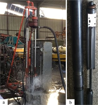
Fig. 10Schematic of the experimental system
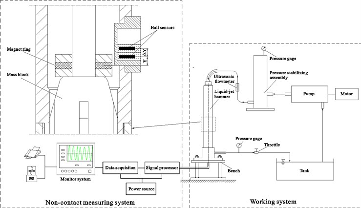
In order to validate the consistency between the experiments and the simulations, a series of bench tests were conducted. As shown in Fig. 10, the tested liquid-jet hammer was driven by a high pressure triplex pump which supplied clean water to it. The flow rate of the feed water was measured by an ultrasonic flowmeter and was adjusted by changing the speed of the electric motor which was the power source of the triplex pump and its speed can be varied by an inverter. A pressure stabilizing cylinder was used to reduce the fluctuation of flow rate. Besides, a non-contact measuring system based on the Hall sensors was employed to measure the backward impact velocity and impact frequency of the impact body. The non-contact measuring system mainly contained a magnet ring, a pair of Hall sensors and a data analysis system. The integrated Hall sensors can provide an output voltage proportional to the magnetic intensity. The cylindrical magnet was fastened to the lower end face of the mass block. Two Hall sensors with the same specifications, one above the other, were mounted in pairs on the wall of the mid tie-in. The distance between the two Hall sensors was 1.0 mm. The magnet ring moves up and down with the movement of the impact body. When the distance between the lower Hall sensor and the magnet ring was , assuming that the corresponding output voltage of the sensor was , and when the impact body moves continuously with a distance of , then the distance between the upper Hall sensor and magnet ring was also , thus the produced corresponding output voltage of the upper sensor was also . The moving time corresponding to the distance was recorded during the movement of the impact body. As the distance of was small enough, the impact velocity of the impact body was approximately equal to .
Table 3 listed the results obtained by CFD simulation and experimental tests. The input flow rates were 200 L/min. It can be found that the result data obtained by CFD simulation is slightly different with that of the experimental tests, but the differences are very small and do not exceed 8 %, showing considerable agreement between them. The relative error may be caused by the fact that leakage and frictional force in the working chambers was ignored in the numerical calculation, and as the value of cannot be infinitely small the measurement of impact velocity was an approximation.
Table 3Comparison of the results (backward impact velocity and impact frequency) obtained by CFD simulation and experimental tests. (The difference is smaller than 8 %)
Backward impact velocity (m/s) | Impact frequency (Hz) | ||
CFD | Exp. | CFD | Exp. |
2.68 | 2.5±0.2 | 14.6 | 13.7±0.5 |
Fig. 11The effect of downhole pressure on the performance of the liquid-jet hammer with buffer structure
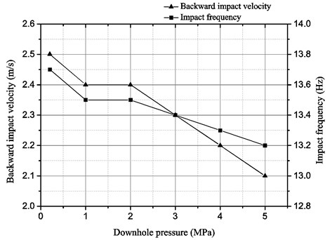
The work performance of most of the DTH hammers is greatly affected by downhole pressure. Though the liquid-jet hammer is one type of the DTH hammers which can be hardly affected by the downhole pressure due to its unique working principle, but the quantitative and detailed measured results are still rarely reported. It is meaningful to investigate the effect of downhole pressure on the performance of the liquid-jet hammer. As shown in Fig. 10, a throttle between the bench and the tank is used to adjust the backpressure of liquid-jet hammer so as to serve as the downhole pressure and a pressure gauge is used to read its pressure value there. The input flow rate was kept 200 L/min. Fig. 10 shows the variations of the backward impact velocity and the impact frequency versus the downhole pressure. When the downhole pressure increased from 0.2 MPa to 5 MPa, both of the backward impact velocity and the impact frequency decreased, but the extent of variation was quite small. This may be attributed to that the increase of downhole pressure would increase the pressure difference between the inner and outer fluid of the cylinder chamber, which increased the interaction force caused by hydraulic clamping between the cylinder lid and the piston rod.
7. Conclusions
In this paper, CFD simulations with dynamic and sliding meshes have been conducted to study the buffer performance of the newly designed buffer structure in a liquid-jet hammer. Results showed that all the geometric parameters of the buffer structure in the liquid-jet hammer have a significant effect on its buffer performance and each of them has an optimum value resulting in a lower backward impacting energy of the impact body. Nevertheless, when the geometric parameters values of the buffer structure in the liquid-jet hammer are smaller or larger than a certain value, the bi-stable fluidic amplifier will not work, for the liquid jet caused by pressure pulsation at the control nozzles is not strong enough to push the supply jet to switch to the other side attachment wall. Therefore, the buffer structure for the liquid-jet hammer must be specially designed to meet the requirements of application. In addition, the liquid-jet hammer was designed and manufactured with the optimal geometric parameters of the buffer structure. The experimental tests showed that the agreement between the numerical and the experimental data is quite good. Moreover, the liquid-jet hammer can work in good condition without failure for more than 30 h and produced the ROP of drilling granite blocks with 140-160 MPa compressive strengths up to 5.2 m/h, hence the working feasibility of the liquid-jet hammer with setting the buffer structure was validated.
References
-
Gabriel W., Michal C., Zuzana J. Deep hole drilling modern disintegration technologies in process of HDR technology. Acta Montanistica Slovaca, Vol. 17, Issue 4, 2012, p. 241-246.
-
Franca Luiz F. P. A bit-rock interaction model for rotary-percussive drilling. International Journal of Rock Mechanics and Mining Sciences, Vol. 48, Issue 5, 2011, p. 827-835.
-
Yin Q. L., Peng J. M., Bo K., He J. F., Kui Y. L., Gan X. Study on dust control performance of a hammer drill bit. International Journal of Mining, Reclamation and Environment, Vol. 27, Issue 6, 2013, p. 393-406.
-
Tuomas G. Water Powered Percussive Rock Drilling: Process Analysis, Modeling and Numerical Simulation. Ph.D. Thesis, University of Lulea Tekniska, 2004.
-
Luo Y., Peng J., Li L., He J., Gan X., Yin K., Zhao Z. Development of a specially designed drill bit for down-the-hole air hammer to reduce dust production in the drilling process. Journal of Cleaner Production, Vol. 112, Issue 1, 2015, p. 1040-1048.
-
Wang D., Zhang W., Zhang X. X. Drilling Techniques for China Continental Scientific Drilling Engineering No.1 Well. Science Press, Beijing, 2007.
-
Jian Z. J., Sang L., Hu G. Q., Zhang W. H. The drilling experiment in geothermal well of DGSC-203 type hydro-efflux hammer. Geology and Prospecting, Vol. 38, Issue 5, 2002, p. 92-93.
-
Deulsch U., Marx C., Rischmuller H. Evaluation of Hammer Drilling Potential for KTB in Supper-Deep Drilling and Deep Geophysical sounding. Springer Verlag, Heidelberg, Berlin, 1995.
-
Li G. G., Suo Z. W., Wang J. C., Gao C. B., Zhang R. L. Application of jet hammer and PDC bit in super deep well. China Petroleum Machinery, Vol. 41, Issue 4, 2013, p. 31-34.
-
Peng J. M., Zhang Q., Li G. L., Chen J. W., Gan X., He J. F. Effect of geometric parameters of the bistable fluidic amplifier in the liquid-jet hammer on its threshold flow velocity. Computers and Fluids, Vol. 82, 2013, p. 38-49.
-
Jian Z. J., Yin K., Jang R. Q., Gu H. L. The research on increasing impacting energy of hydro-efflux hammer. Journal of Changchun University of Science and Technology, Vol. 30, Issue 3, 2000, p. 303-306.
-
Liu H., Yin K., Peng J. M., Yin Q. L. Fracture failure analysis of baseplates in a fluidic amplifier made of WC-11Co cemented carbide. Frattura ed Integrità Strutturale, Vol. 27, 2014, p. 53-65.
-
Zhang Y. G., Peng J. M., Liu H. Buffering the backward impact of piston of liquid-jet hammer. Journal of Jilin University Earth Science Edition, Vol. 40, Issue 6, 2010, p. 1415-1418.
-
Peng J. M, Yin Q. L., Li G. L., Liu H., Wang W. The effect of actuator parameters on the critical flow velocity of a fluidic amplifier. Applied Mathematical Modelling, Vol. 37, 2013, p. 7741-7751.
-
Sun J. Y., Jiao S. J., Huang X. C., Hua H. X. Investigation into the impact and buffering characteristics of a non-Newtonian fluid damper: experiment and simulation. Shock and Vibration, Vol. 2, Issue 2014, 2014, p. 1-10.
-
Chen J. W., Yin K., Peng J. M., Gu Y. L., Zhou B. Numerical simulation of the performance of the SC-89 jet impact system. Proceedings of the 2nd Annual Dynamic Systems and Control Conference Bath/ASME Symposium on Fluid Power and Motion Control. ASME, Hollywood, USA, 2009.
-
Wang C. Y., Zou J., Fu X., Yang H. Y. Study on hydrodynamic vibration in fluidic flowmeter. Journal of Zhejiang University Science A, Vol. 8, 2007, p. 1422-1428.
-
He J. F., Yin K., Peng J. M., Zhang X. X., Liu H., Gan X. Design and feasibility analysis of a fluidic jet oscillator with application to horizontal directional well drilling. Journal of Natural Gas Science and Engineering, Vol. 27, 2015, p. 1723-1731.
-
Mousavian S. M., Najafi A. F. Numerical simulations of gas–liquid–solid flows in a hydrocyclone separator. Archive of Applied Mechanics, Vol. 79, Issue 5, 2009, p. 395-409.
Cited by
About this article

The authors gratefully acknowledge the support of the Public Science and Technology Research Funds Projects of Ministry of Land and Resources of China (No. 201311112) for this work. The authors are also grateful to the reviewers for their helpful advices.
Jianming Peng and Qilei Yin conceived and designed the study. Xinxin Zhang performed the numerical simulations. Xinxin Zhang and Dongyu Wu conducted the experiments. Xinxin Zhang wrote the paper. Jianming Peng, Qilei Yin and Kun Yin reviewed and edited the manuscript. All authors read and approved the manuscript.
The authors declare no conflict of interest.
