Abstract
Development of spherical ultrasonic motor (SUSM) for space is an aim of this investigation. SUSM is a motor of multi-DOF. It's necessary to clear the various conditions to use a motor at space. In this paper, to confirm the durability to the radiant heat from the sun, drive experiments of SUSM was conducted in high temperature condition. As a result, our SUSM maintained the drive performance in high temperature condition. Materials of piezoelectric elements and of adhesives used in SUSM for space were important elements to maintain its drive performance in space. Selection results of the piezoelectric element and the adhesive were also reported in detail.
1. Introduction
Space developments are performed increasingly actively with progress of scientific technique in this century. Attitude control and orbital adjustment of space crafts (for example, artificial satellite, ISS, etc.) in earth orbit are carried out by periodic jet of thrusters. On the other hand, the space crafts which exceed its life span soon are increasing every year and are one of the causes of the space debris increase. Space debris is the artifact which became unnecessary on the circling orbit of the Earth and is so-called space trash. Space debris which increased is one of serious problems, and the danger which strikes against an active space craft is high, and breakdown of a space craft is caused. For example, the next disposal procedure is proposed to space debris. To incinerate itself by atmosphere reentry, a space craft beyond its life span is left from a circling orbit using remaining thruster power. But plural general thrusters without the degree of freedom are be equipped with by a space craft and are one of the cause of the obstruction of downsizing and the increase of weight. To replace plural thrusters by singular thruster with multi-DOF motor contributes to downsizing of a space craft, reduction in launch cost and energy conservation.
The purpose of this investigation is to develop a spherical ultrasonic motor (SUSM) [1-3] for space. The SUSM is a miniature multi-DOF motor. SUSM is very compatible with a small-sized artificial satellite of increased tendency. The various performances are necessary for an actuator for space. In this investigation, it was experimented on durably under high temperature condition to investigate the durability to the radiant heat by the sun. As a result, it was confirmed that SUSM for space retains the drive performance in the high temperature condition. The materials of the piezoelectric element and adhesives which have influences on the performances of SUSM for space are described attentively.
2. Spherical ultrasonic motor
2.1. Feature of SUSM
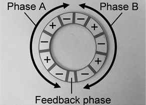
Main components of ultrasonic motor are a rotor which is a drive part and a stator which attached a piezoelectric element and a metallic elastic body. The mechanical oscillation with the ultrasonic range beyond 20 kHz is a drive source for ultrasonic motor. Its structure is indicated on Fig. 1. The piezoelectric element and the metallic elastic body are attached by an adhesive. The piezoelectric element seen from the top and the side are indicated on Fig. 2 and Fig. 3 respectively. The piezoelectric element is divided into 11 parts. When the positive voltage is impressed, the parts of “+” indicated in the Fig. 2 expand in the circumference direction, and when the negative voltage is impressed, those parts shrink in the circumference direction. On the other hand, the parts of “–” indicated in the Fig. 2 shrink by the positive voltage, and expand by the negative voltage. When the sinusoidal wave alternating current voltage of two, the phase A and the phase B, is impressed on the piezoelectric element, the piezoelectric element generates travelling wave as combined wave of input to two phases. This travelling wave appears on the circle surface of the metallic elastic body, and drives the rotor forced on the circle. When the phase difference of the input sinusoidal wave of the phase A and the phase B is changed, the velocity of the travelling wave changes. Therefore, the rotation speed of the rotor can be controlled by the phase difference of the input voltage.
Fig. 1Construction of ultrasonic motor
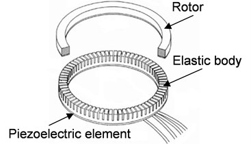
Fig. 2Polarization pattern of piezoelectric element
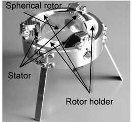
The SUSM is indicated on Fig. 4. The rotor is a sphere and the stator is arranged in three points around the rotor. When rotation vector of the drive force generated by one of stator is composed, the spherical rotor can be rotated on an optional axis. The direction of rotation is controlled by setting the phase difference of two of input sinusoidal wave alternating current voltage to each stator. The SUSM has the following merits in comparison with an electromagnetic motor: (1) having 3DOF by oneself, (2) miniaturization of a motor is easy because a structure is simple and a reduction gear is unnecessary, (3) having high torque and high response in low speed area for a direct drive by friction, (4) a brake is not necessary to have holding torque without turning on electricity, and (5) an electric field and a magnetic field do not influence. These merits have big advantage as the actuator applied to the spacecraft like an artificial satellite and have big advantage to the applicability to the robot for operations used under the MRI environment and the small robot which checks inside the water pipe or the gas pipe. On the other hand, when the piezoelectric element to generate drive force of SUSM exceeds some temperature, piezoelectric falls suddenly, and the rotor cannot be driven any more. This temperature is called a Curie temperature. Unless polarization work is performed again, the piezoelectric element beyond the Curie temperature does not restore piezoelectric. Therefore, SUSM cannot be used under the temperature condition beyond the Curie temperature of the piezoelectric element.
Fig. 3Electrostrictive behavior
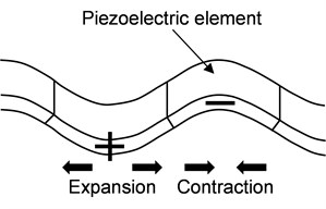
Fig. 4Schematic of SUSM
2.2. Specification of motor for space
Diameters of the stator and the rotor are 30 mm and 45 mm respectively for the size in SUSM for space developed by this investigation. These are the appropriate size as thruster of an artificial satellite. The performances as shown in the below are required for the actuator used as components of a space craft. It's necessary to satisfy the requested whole performances to use SUSM at the space.
1) Drive under the ultrahigh vacuum environment (approximately 10-6 Pa).
2) Heat-resistant under a vacuum.
3) Outgassing is not released under a vacuum.
4) Shock and oscillation resistance at launch (100 Hz, 20 G).
5) Radiation resistance at space.
6) Drive without maintenance within an operating term of an artificial satellite.
In space, an artificial satellite receives radiant heat from the sun and radiates heat to space by the surface opposite to the artificial satellite. Therefore, outer surfaces of an artificial satellite receive severe heat cycles. The performance is estimated by taking a heat cycle from the +120 °C to the –120 °C from outside by a performance testing to a part for space in JAXA (Japan Aerospace Exploration Agency). Drive of SUSM in high temperature condition from normal room temperature to the +120 °C within this temperature range was set as the first target by this investigation. On the other hand, the jet of the thruster for attitude control and orbital adjustment of a space craft is performed the annual average 20 times, and 20 seconds for once are needed. Therefore, when setting a durable period of a space craft to 10 years, it was decided that drive time of 70 minutes in total is a durable target by this investigation.
3. Evaluation of piezoelectric element
3.1. Selection of piezoelectric element
The Curie temperature of the piezoelectric element of the previous SUSM was 120 °C. When a piezoelectric element causes electrostrictive strain, most of various loss (for example, piezoelectric loss) is generated as heat. The heat which generated does not radiate at space of the vacuum environment, and stay around stator. As a result, when the temperature of stator in SUSM for space reached about 120 °C estimated at space, the temperature of stator will be the temperature higher than 120 °C. Accordingly, the drive performance of the previous SUSM is not kept in the high temperature condition which set the surrounding temperature to 120 °C.
So selection of a piezoelectric element with a high Curie temperature was attempted. The conditions about the piezoelectric element requested as SUSM for space are that the Curie temperature is more than 300 °C and that the electromechanical coupling coefficient, the mechanical quality coefficient and the piezoelectric constant are high respectively. The electromechanical coupling coefficient represents the conversion efficiency to the mechanical energy observed as the amplitude of vibration of the travelling wave from electrical input. The mechanical quality coefficient represents the size of the elasticity loss of a piezoelectric element which has an elastic deformation. And the piezoelectric constant represents the size of the strain of the piezoelectric element by the given electric field. From selecting condition based on the above, the N6 material made by NEC/TOKIN Co. satisfied with the condition as a piezoelectric element using by SUSM for space was selected. Table 1 summarizes the main physical properties value of N6 material. Here, this piezoelectric element is called N6 piezoelectric element. The Curie temperature of N6 piezoelectric element is 325 °C, and it is expected to indicate piezoelectric in assumed high temperature conditions.
3.2. Evaluation of selected piezoelectric element
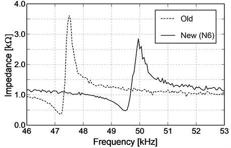
The results by which the torque and the number of rotations were measured about new SUSM using a selected N6 piezoelectric element and previous SUSM are shown in Table 2. The results by which those impedances were measured using an impedance analyzer are indicated on Fig. 5. On condition that impedances were measured in the normal temperature (25 °C) and the atmosphere pressure. The frequency which indicates a local minimal value of impedance in an impedance curve of a piezoelectric element is called a resonant frequency. Ultrasonic motor shows the biggest output of power at this frequency. And an indicator to the size of the piezoelectric effect is the difference between the local minimum value and the local maximum value of the impedance, or the closeness of the resonant frequency and the anti-resonance frequency of the impedance. On condition that anti-resonance frequency is the maximum of the impedance.
On the other hand, to measure the torque of SUSM, a load by the weight hanged through a pulley was given to the axis installed in the spherical rotor. It was confirmed from Table 2 and Fig. 5 that changes to the new piezoelectric element from the previous piezoelectric element do not give a remarkable change to the torque, the number of rotations and a resonant frequency.
Table 1Material constant of piezoelectric element
Dielectric loss | [%] | 0.3 |
Electromechanical coupling factor | [%] | 55.0 |
Mechanical quality factor | 1500 | |
Curie temperature | [°C] | 325 |
Table 2Torque and rotation speed of SUSM
Piezoelectric element | Torque [mNm] | Rotation speed [rpm] |
Old material | 29.3 | 74.2 |
New material (N6) | 41.5 | 62.5 |
Fig. 5Impedance characteristic of piezoelectric element at 25 °C
3.3. Performance test of piezoelectric element
To confirm that a selected N6 piezoelectric element shows piezoelectric in high temperature condition, the measurements of the impedance were conducted while raising the stator temperature of SUSM. A thermocouple was installed in the surface of the stator using N6 piezoelectric element as shown in Fig. 6 and it was set in the thermostatic chamber. After the stator temperature was the state of thermal equilibrium equal to the temperature in the chamber set as 50 °C, the impedance of the stator was measured. And the measurement of the impedance was conducted every 10 °C until the temperature in the chamber was 100 °C from 50 °C. The used thermostatic chamber (DQ-50SL special type) which made by Sato vacuum machine Industry Company is indicated on Fig. 7. Heating was used the outside direct heat system by the seeds heater (200 V, 6 kW) in chamber.
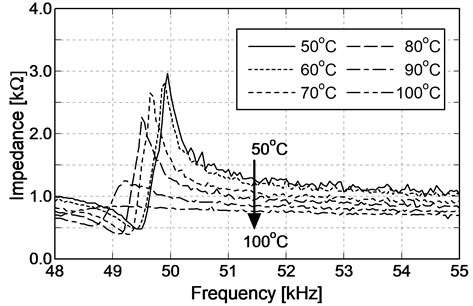
When making the temperature of the stator surface rise every 10 °C from 50 °C to 100 °C, results of the acquired impedance characteristic are indicated on Fig. 8. When the temperature of the stator was 50 °C, the impedance showed a remarkable change in the neighborhood of the resonant frequency and the anti-resonance frequency. The change of impedance in the neighborhood of a resonant frequency and anti-resonance frequency was gently while rising the temperature of stator, and when it was 100 °C, the sharp peak of the impedance curve has disappeared clearly. Further when the measurement of the impedance was conducted in the same way while falling the temperature of the stator from 100 °C to 50 °C, the result similar to Fig. 8 was obtained. As mentioned above, because there is reproducibility in loss of piezoelectric by the temperature, the prediction that the internal temperature of the piezoelectric element reached the Curie temperature as the cause of the loss of piezoelectric by about 100 °C is excluded.
Fig. 6Stator using N6 and setting of thermocouple
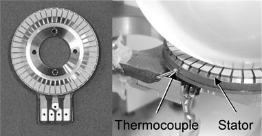
Fig. 7Thermostatic chamber
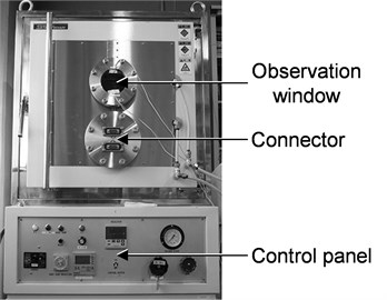
Fig. 8Impedance characteristic of stator using N6 material
So adhesive softening was predicted as the cause which has caused loss of piezoelectric in high temperature condition. The thermosetting adhesive is used in SUSM to attach a piezoelectric element and a metallic elastic body. The travelling wave generated by electrostrictive strain of a piezoelectric element transmits to a metallic elastic body through the adhesive, and driving force is caused in the rubbing surface with rotor. To perform molecular motion dramatically in high temperature condition, the thermosetting adhesive increases liquidity. The temperature by which the adhesive begins to signify liquidity is called glass transition temperature. When driving ultrasonic motor by temperature environment higher than this temperature, the travelling wave which generated by a piezoelectric element is not transmitted by adhesive buffer action to a rotor rubbing surface. When the adhesive is softened, a load of deformation by the metallic elastic body which was controlling elastic deformation of a piezoelectric element disappears, and the impedance falls. Further, a sudden change about impedance in the neighborhood of a resonant frequency and an anti-resonance frequency are lost. When the adhesive beyond glass transition temperature is refrigerated, the adhesive is hardened again and the travelling wave generated by the piezoelectric element is transmitted to the metallic elastic body again.
4. Evaluation of adhesive
4.1. Selection for adhesive
The evaluation based on measuring result of the impedance in high temperature condition was conducted to an adhesive used in SUSM for space. Selecting conditions of an adhesive appropriate about SUSM for space is that glass transition temperature is high, that bonding strength detached and shearing bonding strength after hardening in non-conductivity are large, and that the hardness after hardening is high. For oscillation by electrostrictive strain of a piezoelectric element to apply heavy load to the all-direction to an adhesive, the intensity of the adhesive has to be maintained by the shearing and the detaching direction powerfully. The intensity of the adhesive layer has to be high after adhesive hardening to transmit the oscillation of the travelling wave generated by a piezoelectric element to a metallic elastic body without attenuating in adhesive layer.
Three kinds of adhesives selected based on adhesive selecting conditions are compared. Tables 3-5 summarize the main physical properties value of adhesives.
1) Made by ThreeBond Co., Ltd., TB2285.
2) Made by Aremco Products Inc., Aremco-Bond 570.
3) Made by Tokyo Chemical Industry Co., Ltd., B1796/M0567/D0688 (3 liquid mixtures).
Table 3Characteristics of TB2285
Contents | Features |
Component | Bisphenol F epoxy resin, Epoxy resin and inorganic filler, Dicyandiamide C2H4, Diuron C9H10Cl2N2O, Silica |
Viscosity | 1400 Pa s |
Glass transition temperature | 180 °C |
Longitudinal shear strength (200 °C) | 3.9 MPa |
Table 4Characteristics of AREMCO 570
Contents | Features |
Component | Phenolic resin, Phenol, Carbon black, Methyl Ethyl Ketone, Isopropyl Alcohol, Ortho-Cresol, Formaldehyde |
Viscosity | 35 Pa s |
Heat proof | 316 °C |
Tensile shear strength | 14.5 MPa |
Table 5Characteristics of 3 chemicals
Items | Features |
B1796 | 2,2-bis (4-glycidyloyphenyl) propane |
M0567 | 4-methylcyclohexane-1, 2-dicarboxylic anhydride |
D0688 | N, N-dimethylbenzylamine |
The stators using these adhesive were produced respectively and drive experiments of a spherical rotor were conducted using the laboratory equipment for driven of single axis indicated on Fig. 9. As a result, only a stator using TB2285 made the spherical rotor revolve.
The causes which the stator using Aremco-Bond 570 could not drive the spherical rotor are two. For one thing, the bubbles in adhesive phase are generated as gluing because the viscosity before adhesive hardening becomes very high. For another, the traveling wave in adhesive phase is damped because the adhesive phase is too thick. In particular, when bubbles are mixed in adhesive phase, loads to adhesive phase by high frequency vibration of the piezoelectric element generate cracks around the bubbles, and transmission of travelling wave is prevented. The adhesive dividing by expansion of the crack will be the cause which detaches the piezoelectric element from the metallic elastic body. When the stator temperature rise, the bubble is expanded by the heat, and the travelling wave which generated by the piezoelectric element cannot be transmitted. On the other hand, 3 liquid mixed adhesive which made by Tokyo Chemical Industry is detached adhesive phase as drive, and cannot be driven spherical rotor.
We decided using TB2285 to consider the experimental result, simplicity of the stator production, and stability of the adhesive properties. Further the glass transition temperature of TB2285 is 185 °C, and it's expected to transmit the traveling wave without softening in high temperature condition of the target (120 °C).
4.2. Evaluation of selected adhesive
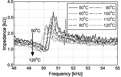
The selected adhesive TB2285 was used to produce the stator. And measurements of impedance were conducted while heating it in the thermostatic chamber. The N6 piezoelectric element selected at the previous chapter was used for a piezoelectric element. Fig. 10 is impedance characteristic of a measured result. When comparing with the result indicated on Fig. 8, it was indicated to maintain piezoelectric in high temperature condition by using TB2285 as the adhesive of the stator. Further, sharpness of the impedance curve does not also disappear in high temperature condition of the target (120 °C), and maintenance of piezoelectric is achieved.
Fig. 9Single axis SUSM using selected adhesive
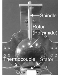
Fig. 10Impedance characteristic of stator using selected adhesive
5. Durability of heat load to SUSM for space
5.1. Performance evaluation by separate stator
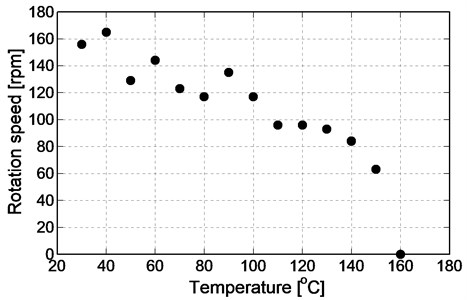
Selected piezoelectric element, adhesive and metallic elastic body were used to produce the stator newly. And the drive experiments were conducted for the performance assessment of the separate stator. The drive experiment is carried out giving heat load to rise temperature of the stator in the thermostatic chamber. Polyimide was used for the material of the spherical rotor. It’s appropriate to SUSM for space because the polyimide is used actually as the structure material for space. To confirm the performance to the produced separate stator, drive experiment was conducted using single axis laboratory equipment indicated on Fig. 9. The surface temperature of the stator was raised gradually from 30 °C to 160 °C while heating in the thermostatic chamber, and the motor was driven respectively for 20 seconds by the temperature every 10 °C. For the purpose of confirming the change in the number of rotations of the motor with a rise of the temperature, the drive state of the motor was recorded by a video camera and the number of rotations was calculated from the frame rate of the animation and the number of record frames.
The experimental results are indicated on Fig. 11. The rotation rate of the spherical rotor is decreasing gradually with temperature rise of the stator, but the motor is also driving in 120 °C of high temperature condition as a target. When temperature of the stator was 160 °C, and the wiring was broken due to high temperature, and the rotation of spherical rotor was stopped.
The lower of rotation speed with a rise of the temperature is the cause that the temperature inside the stator by the heat generating from the piezoelectric element is rose. When the piezoelectric element is carried out an elastic deformation by a piezoelectric effect, the input energy is lost as heat due to elasticity loss and piezoelectric loss. This reason can be expressed by the summation of the loss of the electromechanical coupling and the dielectric loss. The square root of the ratio of the given electric energy to the generated mechanical energy is the electromechanical coupling factor ( 55 %). Then the loss is 69.75 % by subtracting the squared electromechanical coupling factor from 1. About 70 % of the electric power which is inputted in case of N6 piezoelectric element is released as heat because dielectric loss tan δ is 0.3 %. The stator is not only heated by heat load from outside of the piezoelectric element but also from inside of it by this heat. Therefore, the temperature of the adhesive phase is higher than the temperature of the external environment, and the transmission of the traveling wave is difficult to approach the glass transition temperature of the adhesive. As a result, the rotation speed of the spherical rotor lowed.
Fig. 11Result of limit temperature experiment (single axis)
5.2. Test of durability with heat load
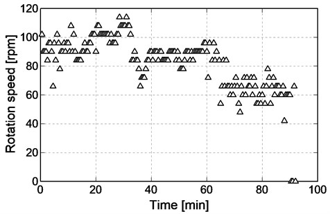
The durable experiment by a heat load was conducted using the laboratory equipment for driven of single axis. The laboratory equipment was installed in the thermostatic chamber, and the temperature in the thermostatic chamber was set as 120 °C. After standing until it became equivalent in the temperature of the stator and the thermostatic chamber, the motor was driven for 20 seconds. And suspension for 1 minute was given to the motor, and the motor was driven for 20 seconds again. These movements were repeated and variations of the rotation rate to accumulated drive time were confirmed. A thruster jet of an artificial satellite is based on movement performed for about 20 seconds once per 2-3 weeks in space. The experimental state is recorded by a video camera. The rotation rate of the motor was calculated from the number of the frame and a frame rate recorded by the video camera.
The experimental result is indicated on Fig. 12. Drive for 70 minutes set as target time succeeded because a spherical rotor was driven for 90.5 minutes in 120 °C of the high temperature condition. But, accumulation of above-mentioned internal generated heat is considered as the cause laboratory equipment suspended 90.5 minutes later. In this experiment, downtime of stator was set to 1 minute to reproduce intermittence drive of the thruster. But the heat generated by piezoelectric loss for pause of the stator was not radiated sufficiently. The heat, then, was stored within the stator, and the drive performance was made worse.
In addition, the factor of heat is a small pressing power between the stator and the spherical rotor. The designed value of the pressing power between the stator and the spherical rotor of SUSM is 6.9 N. The only own weight of the spherical rotor is generated the pressing power to check the performance of the stator by single axis experimental device. When the pressing power is small, the travelling wave which generates the surface of the stator is not forced on the spherical rotor. Then the heat by elasticity loss is increased because the elastic deformation between the metallic elastic body and the whole piezoelectric element is big. Therefore, the inside heat of the stator is more increase than expectation, and the drive performance was made worse with the temperature rise of the stator.
Fig. 12Result of heat load experiment (single axis)
5.3. Test of durability with heat load to SUSM for space
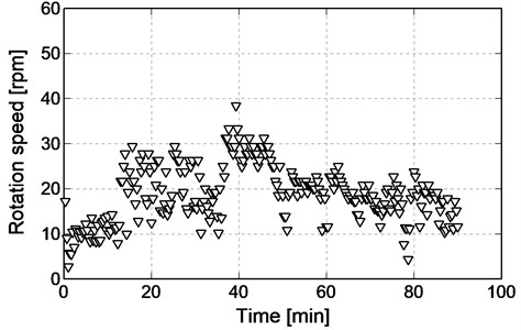
Experimental SUSM for space was produced using N6 piezoelectric element and TB2285 adhesive selected based on the above mentioned experiment. The experimental model is indicated on Fig. 13. The durable experiment of the heat load was conducted by the same way as single axis of drive experiment above-mentioned using the experimental model. Further, the experimental SUSM was driven along the direction of the rail for 20 seconds. The suspended time was set as 1 minutes so that generated heat by a piezoelectric element might radiate perfectly.
The experimental results are indicated on Fig. 14. The durability by the heat load was experimented on using the experimental SUSM. As a result, 70 minutes set as the target in drive time accumulated were achieved. The drive performance beyond 90.5 minutes which are above-mentioned drive time accumulated was confirmed. At this time, the experimental SUSM also maintained the drive state beyond 90 minutes. Therefore, the selected result of the piezoelectric element and the adhesive are satisfied the drive performance which is required an actuator for space in +120 °C of high temperature condition assumed at space.
Fig. 13Schematic of experimental SUSM for space using selected materials
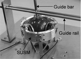
Fig. 14Result of heat load experiment (experimental SUSM for space)
6. Summary
The target of this investigation is development of spherical ultrasonic motor (SUSM) for space. Maintenance of the drive performance is also requested of an actuator for space in the special environment. And the durability in the high temperature condition was experimented on to our SUSM, and the maintenance of the drive performance was confirmed in this paper. The numerical value of the target to the durability was established as estimated drive time beyond 70 minutes in +120 °C of high temperature condition.
To request the high Curie temperature of a piezoelectric element to drive of SUSM for space in high temperature condition, selection of the piezoelectric element was carried out at first. The selection of adhesive to which the piezoelectric element and the metallic elastic body are attached was performed at the same time because the glass transition temperature of an adhesive in high temperature condition was an important problem as the result. The stator of SUSM for space maintained the piezoelectric performance in high temperature condition by the appropriate selection result of the piezoelectric element and the adhesive. And when the experimental SUSM for space was produced using the selected material, and the durability by the heat load was experimented on in high temperature condition, 70 minutes in estimated drive time set as the target were achieved.
In the future, the drive performance of SUSM for space will be evaluated in the –120 °C of low temperature condition supposed as space temperature condition. Further, the drive performance to ±120 °C of heat cycle which supposes operational condition in the space will be evaluated, and actualization of SUSM for space will be aimed at.
References
-
Oohashi T., Nishizawa U., Fukaya N., Toyama S. Spherical ultrasonic motor for space. Proceedings of the 6th ICMDT, Vol. 15, Issue 204, 2015, p. 258-259.
-
Toyama S., Oohashi T., Fukaya N. Development of spherical ultrasonic motor for space. Proceedings of Actuator, Vol. 14, 2014, p. 289-292.
-
Oohashi T., Toyama S. Development of spherical ultrasonic motor for space. Applied Mechanics and Materials, Vol. 555, 2014, p. 26-31.
About this article

