Abstract
Damping is a mechanism of energy dissipation in shock and vibration. It is difficult to obtain the damping coefficient by theoretical method accurately because of varying material properties, vibration velocity and frequency, especially for the millisecond delay blasting in tunnel excavation. Therefore, the most effective method is simulation inversion by employing large-scale monitoring data, accurate blast loading model and detailed mechanical parameters. In this paper, in-situ monitoring data was acquired by Blasting Vibration Recorder. The accurate blast loading was calculated on the basis of neural network method, so the contribution rate coefficient of every sequence blasting in total millisecond delay blasting could be confirmed. Mechanical parameter of the host rock was acquired by Split Hopkinson Pressure Bar (SHPB) test. In order to predict the simulated velocity, the numerical model in physical dimensions was built by FLAC3D, alongside the constitutive parameters from laboratory tests and different damping coefficients. Compared with the monitoring attenuation law, the damping coefficient of host rock could be finally confirmed.
1. Introduction
Nowadays, with the thriving development of infrastructures and mining activities, blasting is widely used because of its extensive applicability to various geological conditions. Borehole-blasting methods are adopted in modern constructions, especially in mountain tunnels and metal mine excavations. After the explosive energy broke the rock mass, the residual energy will generate shock or vibration wave in the host rock. For this wave, damping is the mechanism of energy dissipation, and it can make the wave weaken along with time till cease at last. Domestic and overseas scholars have paid attention to damping researches. Elmenshawia et al., evaluated the effective damping mechanisms, damping ratios and the natural period of vibration by using laboratory test and calculation [1]. Rezaiee-pajand et al. raised a new fictitious viscous damping method to determine the dynamic problem [2]. Hubbard and Mavroeidis studied the damping coefficients for near-fault ground motion response spectra [3]. Crow et al. measured the monofrequency in situ damping in Ottawa area soft soils [4]. Lu et al. did an experimental study on a generalized Maxwell model for studying the nonlinear viscoelastic dampers, which is used in seismic isolation [5]. Araei et al. researched the Loading frequency effect on damping of rockfill materials [6]. Sarlin et al. studied the vibration damping properties of steel/rubber/composite hybrid structures [7]. Senetakis et al. calculated the damping ratio curves of quartz sand and rhyolitic crushed rock [8]. Omidi et al. comparatively analyzed the seismic cracking of concrete gravity dams by plastic–damage model using different damping mechanisms [9]. Khoshnoudian et al. raised the damping coefficients for soil-structure systems [10]. Jin et al. adopted a unified method for the vibration and damping analysis [11]. Boaga et al. analyzed the Soil damping influence on seismic ground response [12]. Despite some achievements have been accomplished, most of present studies are based on theoretical researches and laboratory scale studies. There are still many uncertain problems to be settled because of different vibration source, complex dynamic process and various material properties.
Numerical simulation has become an important prediction method in the engineering, due to its high accuracy and less cost. Also, the fast development of computer technique makes many scholars use softwares to solve blasting problems [13-20]. Most of these models adopt simplified triangle dynamic load, trapezoid dynamic load or simplified data table in analysis. In addition, the influence of damping is ignored. Therefore, these analysis is not accurate enough for the blasting loading, especially for the millisecond delay blasting in highway tunnels. Taking advantage of computer technique, scholars generally employed neural network method in engineering problems, such as modeling damping ratio and shear modulus [21], building a new generation of rock failure criteria [22], modeling uniaxial compressive strength of building stones [23], analyzing the true triaxial stress state and determining the intermediate principal stress effects on intact rock strength [24], modeling complex dynamic systems [25] and estimating the seismic velocity [26].
In order to determine the damping coefficient of millisecond delay blasting, in this paper, in-situ monitoring data was acquired by Blasting Vibration Recorder. The accurate blast loading was calculated on the basis of neural network method to analyze the proportionality coefficient of every sequence blasting in total millisecond delay blasting. Mechanical parameter of the host rock was confirmed by Split Hopkinson Pressure Bar (SHPB) test. The numerical model in physical dimensions was built by FLAC3D, accepting the constitutive parameters from laboratory tests and different damping coefficient, to predict the simulated velocity. In the last, compared with the monitoring attenuation law, the damping coefficient of host rock could be confirmed.
2. In-situ monitoring data
In order to fit the perfect attenuation law, collecting accurate body wave and surface wave field data is necessary. There is a dumped air-raid shelter on the top of tunnel between 3 m to 12 m. The sketch map between the air-raid shelter and tunnel is shown in Fig. 1.
Fig. 1The location of shelter and the monitoring points
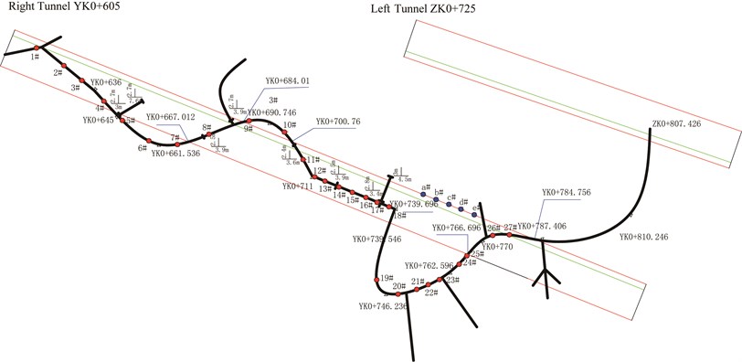
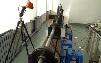
It is possible to monitor the body wave in host rock before excavation, owe to the advantageous monitoring condition of the air-raid shelter. The main monitoring project consisted of two parts. One is in the air-raid shelter. Instal the sensor in the drilled hole along the tunnel design line before the cutting surface (Fig. 2(a)), so 27 monitoring points between YK0+600 to YK0+780 were set to implement to reach 37 times data collection under different collapse distance. The monitoring points were indicated as the red dots in Fig. 1. The monitoring data was fitted in Fig. 3(a). The other one is using the general three-dimensional vibration sensor in the tunnel floor, and 5 monitoring points between YK0+730 to YK0+770 were selected to achieve 12 times data collection under different collapse distance. The monitoring points were indicated as the blue dots in Fig. 1. The monitoring data was fitted in Fig. 3(b).
Fig. 2In-situ monitoring project
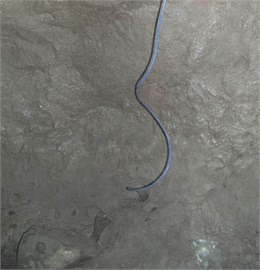
a) Poured sensor
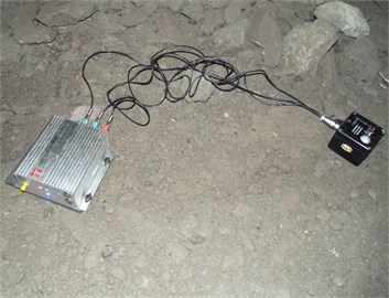
b) General three-dimensional sensor
Fig. 3In-situ monitoring data
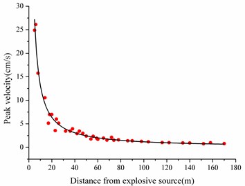
a) Body wave
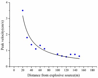
b) Surface wave
3. SHPB tests for dynamic parameters
The blasting problem is a typical dynamic problem, so the mechanical parameters of host rock should be obtained from the impact tests. The most common impact test is SHPB test. The typical SHPB test system is comprised of impact bar, incident bar and transmission bar. The particular form is shown in Fig. 4.
Fig. 4The particular form of SHPB test system
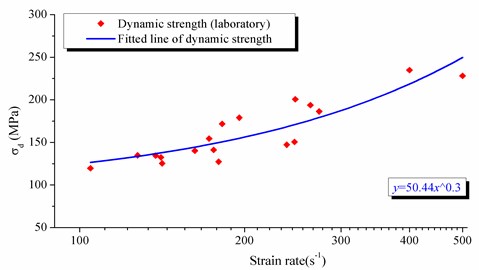
The rock in the tunnel area belongs to the late Jurassic sandstone. In this paper, 18 rock samples were conducted by SHPB test. The failure situation and dynamic compressive strength of 18 sandstone samples under different strain rate are shown in Fig. 5 and Fig. 6 respectively.
Fig. 5The failure situation of sandstone samples under different strain rate

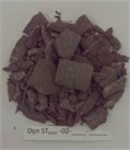

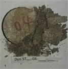


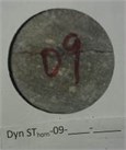

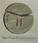

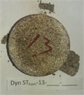


Fig. 6The failure situation of sandstone samples under different strain rate
4. The contribution rate of segment blasting
In FLAC3D, there are three different damping of local damping, hysteresis damping and Rayleigh damping. In this study, local damping was chosen as the simulation inversion object because the increased weight of the elements is equal to the decreased weight of the elements during the whole simulation. Therefore, through analyzing the increased or decreased weight on the unit node, the convergence of vibration can be indicated.
The traditional blasting load model is simplified to triangle dynamic load, trapezoid dynamic load or simplified data table. They are all not accurate enough for the blasting loading. Li et al. established an accurate blasting load by considering the blasting pressure change, the blast holes volume expansion, the fracture development and the blasting gas motion and dividing the whole explosion process into four stages [27]. Thus, the blasting load model was shown in Fig. 7. Li et al. adopted an equivalent elastic vibration boundary method to simulate the blasting in tunnel, and raised the range of this boundary is 10 times of the blasthole diameter by 4 simulation tests was carried out [27]. In these tests, the depth of blast hole was 100 mm, the diameter was 40 mm, charged by No. 2 emulsion explosives with the 70 mm length. The length of fillings was 10 mm. the whole blasting process was monitored by Acoustic Emission (AE) system. Also, in order to guarantee the veracity, the numerical simulation by LAC3D also was validated. The typical process pictures are shown in Fig. 8
Fig. 7Blasting loading model
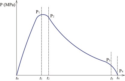
Fig. 8The confirming process of equivalent elastic vibration boundary
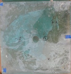
a) In-situ model before explosion
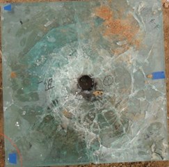
b) In-situ model after explosion
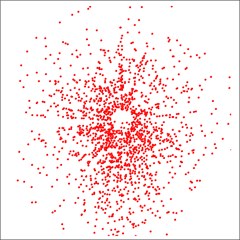
c) AE monitoring result
d) Numerical simulation result
Usually, the millisecond delay blasting in highway tunnels has seven segments to process exploding with micro time-scale difference (Fig. 9). Meanwhile, different waves from different segments are superposed, which makes it difficult to use the above deduced blasting load model. Hence, a contribution rate coefficient was proposed to represent the different contribution of each segment blasting in the whole blasting process. As shown in Fig. 9, the diameter of blasthole is 4 cm, and the distance between two holes is 60 cm. It is easy to calculate that the range of elastic vibration boundary is 40 cm. He et al., (2015) proposed an idea to estimate the range of Dynamic Saint-Venant’s Principle (DSVP) in a cylindrical waveguide by using the modified SHPB and numerical simulation [28], as shown in Fig. 10, By taking advantage of the dynamic Saint-Venant’s Principle in a cylindrical waveguide, theoretically, the value of contribution rate coefficient is less than 133.3 % = 0.4 m/0.3 m.
To guarantee the accuracy of dynamic simulation, the dimensions of element should be less than 1/10 of the vibration wave length. Based on the in-situ monitoring data, the velocity of the wave is 3569 m/s and the frequency is 70 Hz in the host rock. After calculation, the dimensions of element in this simulation model should be less than 5.1 m.
Fig. 9Arrangement plan of blastholes in millisecond delay blasting
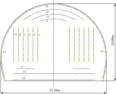
Fig. 10DSVP experiment setup and numerical model [28]
![DSVP experiment setup and numerical model [28]](https://static-01.extrica.com/articles/16961/16961-img32.jpg)
a) Equipment setup
![DSVP experiment setup and numerical model [28]](https://static-01.extrica.com/articles/16961/16961-img33.jpg)
b) Impactor
![DSVP experiment setup and numerical model [28]](https://static-01.extrica.com/articles/16961/16961-img34.jpg)
c) Numerical model
![DSVP experiment setup and numerical model [28]](https://static-01.extrica.com/articles/16961/16961-img35.jpg)
d) Numerical convergence test on the element size
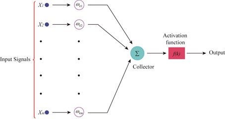
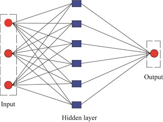
In interest of obtaining the contribution rate coefficients (, , , , , , and ), the neural network training method was adopted to predict 20 groups contribution rate coefficients. The training structure chart and schematic diagram are shown in Fig. 11. The software FLAC3D was used to simulate the peak velocity of different position with the predicted contribution rate coefficient. After taking in-situ monitoring blasting vibration velocity of the tunnel as the objective value, giving consideration to the frequency and arriving time of peak velocity, a group of contribution rate coefficient of different segments, which was verified by the in-situ monitoring velocity, could be established.
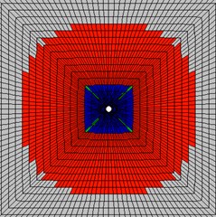
Based on the actual engineering geology and structures, a 3D model (Fig. 12) was built in the finite element software of FLAC3D, accepting the constitutive variables, blasting load and dynamic parameters. The geometrical dimensions are: length 420 m, width 150 m and height 150 m. The finite element mesh consists of 386527 nodes and 372263 elements. The dimensions of elements were 1 m-3.2 m, which is less than 5.1 m. The simulation parameters were shown in Table 1 to Table 3.
Fig. 11Neural network
a) Training structure char
b) Schematic diagram
Fig. 123D model in FLAC3D
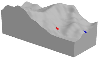
Table 1Physical and mechanical parameters of the Rock
Density (kg/m³) | Compressive strength (MPa) | Tensile strength (MPa) | Friction angle (°) | Poisson’s ratio | Cohesion (MPa) |
2820 | 50.44x^0.3 | 3.0 | 35 | 0.2 | 4.0 |
Table 2Explosive blasting parameters
Charge diameter (mm) | Blasthole diameter (mm) | Holes number | Explosive density (kg/m3) | Detonation velocity (m/s) | Multistage number |
32 | 40 | 180 | 1000 | 3200 | 7 |
Table 3The time interval of every multistage
MS1 | MS3 | MS5 | MS7 | MS9 | MS11 | MS13 | MS15 |
0 | 20 ms | 50 ms | 110 ms | 200 ms | 310 ms | 460 ms | 650 ms |
Table 4The contribution rate of different segments blasting
0.32 | 0.548 | 0.872 | 0.936 | 0.452 | 0.496 | 0.48 | 0.231 |
After continuous trial simulation, a group of contribution rate for different segments was selected, as shown in Table 4. The typical simulated vibration velocity was shown in Fig. 13. By employing this group of contribution rate in simulation, the predict peak velocity is 2.50 cm/s, the in-situ monitoring value is 2.51, and the error is 2 %. The wave shape and frequency were similar, and the comparative result was shown in Fig. 14.
Fig. 13Typical predicted velocity
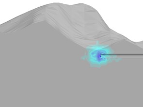
a) blasting
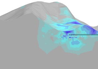
b) blasting
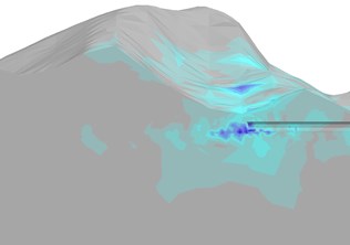
c) blasting
Fig. 14Velocity curves
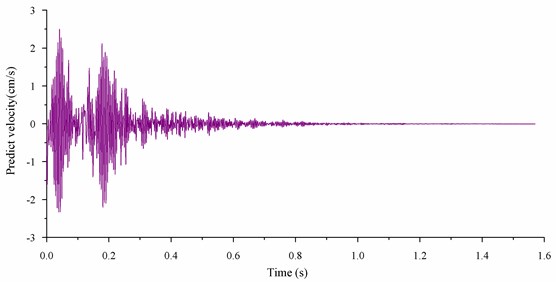
a) Predict velocity
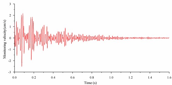
b) Monitoring velocity
5. Determining the damping coefficient
Adopting the equivalent elastic analysis, the 3D model was built in FLAC3D alongside the elastic constitutive, loading model and initial local damping, whose value were evaluated by the past analysis experience. In this simulation, the initial damping value was 0.02, and the simulation time was set as 2 s. After initial simulation, comparing the fitting curve of predicted peak velocity under different distance from explosive source with fitting data from in-situ monitoring, the difference of attenuation law could be made out. Then, through continuously adjusting the local damping value, the ultimate damping value was confirmed, and its value was 0.022. Taking 0.022 as local damping value, the predicted results and the compared curves are shown in Table 5, Table 6 and Fig. 15 respectively.
Table 5Predicted results of host rock under 0.022 local damping value
Element | 8476 | 8573 | 8638 | 8657 | 8598 | 8517 | 8396 | 8264 | 8106 | 7921 | 7717 | 7485 | 7231 | 7868 | 8058 |
Distance (m) | 5 | 10 | 20 | 30 | 40 | 50 | 60 | 70 | 80 | 90 | 100 | 110 | 120 | 130 | 140 |
Velocity (cm/s) | 19.5 | 13.8 | 7.27 | 4.36 | 3.18 | 2.21 | 1.81 | 1.73 | 1.48 | 1.75 | 1.47 | 1.34 | 1.11 | 1.02 | 0.91 |
Table 6Predicted results of tunnel floor under 0.022 local damping value
Element ID | 4521 | 4613 | 4684 | 4721 | 4762 | 5231 | 6058 | 6321 |
Distance (m) | 20 | 40 | 60 | 80 | 100 | 120 | 140 | 160 |
Velocity (cm/s) | 3.63 | 1.65 | 1.20 | 0.92 | 0.75 | 0.64 | 0.56 | 0.51 |
Fig. 15Compared curves between simulation and in-situ monitoring
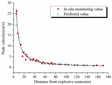
a) In host rock
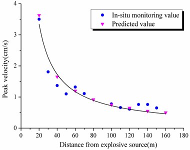
b) On tunnel floor
As shown in Fig. 14, it is obvious that the predicted curves and monitoring results fit well with the local damping value of 0.022. This analysis perfectly illustrates the veracity of simulation inversion method.
6. Conclusions
1) It is possible to monitor the body wave in host rock before excavation, due to the advantageous monitoring condition of the shelter. The main monitoring scheme consisted of two parts. With the poured sensor and normal vibration, a great deal of vibration data was obtained to support the following analysis.
2) Tunnel blasting is a typical dynamic problem. SHPB test on sandstone can provide dynamic parameters for simulation and damping inversion.
3) Neural network training method was adopted to determine the contribution rate coefficient of segment blasting, after considering the accurate blasting load, equivalent elastic boundary and Saint Venant’s Law. The value of contribution rate coefficient is from 0 to 1.33. After continuous trial simulation, a group of contribution rate coefficient of different segments was selected from 20 group training results.
4) At last, a 3D model with the initial local damping, whose value was evaluated by the past analysis experience, was established. After analyzing the difference, the damping coefficient was proved to meet the in-situ attenuation law. Hence, the predicted curves and monitoring results fitted well with the local damping value of 0.022, which interpreted the veracity of simulation inversion method.
References
-
Elmenshawia A., et al. Damping mechanisms and damping ratios in vibrating unreinforced stone masonry. Engineering Structures, Vol. 32, 2010, p. 3269-3278.
-
Rezaiee-pajand M., et al. A new method of fictitious viscous damping determination for the dynamic relaxation method. Computers and Structures, Vol. 89, 2011, p. 783-794.
-
Hubbard T., George Mavroeidis P. Damping coefficients for near-fault ground motion response spectra. Soil Dynamics and Earthquake Engineering, Vol. 31, 2011, p. 401-417.
-
Crow H., Hunter J. A., Motazedian D. Monofrequency in situ damping measurements in Ottawa area soft soils. Soil Dynamics and Earthquake Engineering, Vol. 31, 2011, p. 1669-1677.
-
Lu L. Y., Lin G. L., Shih M. H. An experimental study on a generalized Maxwell model for nonlinear viscoelastic dampers used in seismic isolation. Engineering Structures, Vol. 34, 2012, p. 111-123.
-
Araei A. A., et al. Loading frequency effect on stiffness, damping and cyclic strength of modeled rockfill materials. Soil Dynamics and Earthquake Engineering, Vol. 33, 2012, p. 1-18.
-
Sarlin E., et al. Vibration damping properties of steel/rubber/composite hybrid structures. Composite Structures, Vol. 94, 2012, p. 3327-3335.
-
Senetakis K., Anastasios Anastasiadis, Kyriazis Pitilakis Normalized shear modulus reduction and damping ratio curves of quartz sand and rhyolitic crushed rock. Soils and Foundations, Vol. 53, Issue 6, 2013, p. 879-893.
-
Omidi O., Valliappan S., Lotfi V. Seismic cracking of concrete gravity dams by plastic-damage model using different damping mechanisms. Finite Elements in Analysis and Design, Vol. 63, 2013, p. 80-97.
-
Khoshnoudian F., Ahmadi E., Azad A. I. Damping coefficients for soil-structure systems and evaluation of FEMA440 subjected to pulse-like near-fault earthquakes. Soil Dynamics and Earthquake Engineering, Vols. 61-62, 2014, p. 124-134.
-
Jin G., et al. A unified method for the vibration and damping analysis of constrained layer damping cylindrical shells with arbitrary boundary conditions. Composite Structures, Vol. 130, 2015, p. 124-142.
-
Boaga J., et al. Soil damping influence on seismic ground response: A parametric analysis for weak to moderate ground motion. Soil Dynamics and Earthquake Engineering, Vol. 79, 2015, p. 71-79.
-
Wang Z. L., Konietzky H., Shen R. F. Coupled finite element and discrete element method for underground blast in faulted rock masses. Soil Dynamics and Earthquake Engineering, Vol. 29, 2009, p. 939-945.
-
Wang Z. L., Konietzky H. Modelling of blast-induced fractures in jointed rock masses. Engineering Fracture Mechanics, Vol. 76, 2009, p. 1945-1955.
-
Choi B. H., et al. Case study of establishing a safe blasting criterion for the pit slopes of an open-pit coal mine. International Journal of Rock Mechanics and Mining Sciences, Vol. 57, 2013, p. 1-10.
-
Azizabadi H. R. M., Mansouri H., Fouché O. Coupling of two methods, waveform superposition and numerical, to model blast vibration effect on slope stability in jointed rock masses. Computers and Geotechnics, Vol. 61, 2014, p. 42-49.
-
Deng X. F., et al. Numerical study on tunnel damage subject to blast-induced shock wave in jointed rock masses. Tunnelling and Underground Space Technology, Vol. 43, 2014, p. 88-100.
-
Resende R., et al. Stress wave propagation test and numerical modelling of an underground complex. International Journal of Rock Mechanics and Mining Sciences, Vol. 72, 2014, p. 26-36.
-
Pennetier O.,William-Louis M., Langlet A. Numerical and reduced-scale experimental investigation of blast wave shape in underground transportation infrastructure. Process Safety and Environmental Protection, Vol. 9, Issue 4, 2015, p. 96-104.
-
Zhang B. Y., Li H. H., Wang W. Numerical study of dynamic response and failure analysis of spherical storage tanks under external blast loading. Journal of Loss Prevention in the Process Industries, Vol. 34, 2015, p. 209-217.
-
Cabalar A. F., Cevik A. Modelling damping ratio and shear modulus of sand-mica mixtures using neural networks. Engineering Geology, Vol. 104, 2009, p. 31-40.
-
Rafiai H., Jafari A. Artificial neural networks as a basis for new generation of rock failure criteria. International Journal of Rock Mechanics and Mining Sciences, Vol. 48, 2011, p. 1153-1159.
-
Yurdakul M., Akdas H. Modeling uniaxial compressive strength of building stones using non-destructive test results as neural networks input parameters. Construction and Building Materials, Vol. 47, 2013, p. 1010-1019.
-
Kaunda R. New artificial neural networks for true triaxial stress state analysis and demonstration of intermediate principal stress effects on intact rock strength. Journal of Rock Mechanics and Geotechnical Engineering, Vol. 6, 2014, p. 338-347.
-
Bellamine F., Almansoori A., Elkamel A. Modeling of complex dynamic systems using differential neural networks with the incorporation of a priori knowledge. Applied Mathematics and Computation, Vol. 266, 2015, p. 515-526.
-
Aleardi M. Seismic velocity estimation from well log data with genetic algorithms in comparison to neural networks and multilinear approaches. Journal of Applied Geophysics, Vol. 117, 2015, p. 13-22.
-
Li Q., et al. Blasting vibration safety criterion analysis with equivalent elastic boundary: based on accurate loading model. Shock and Vibration, 2015.
-
He L., et al. Investigation of dynamic saint-venant’s principle in a cylindrical waveguide-experimental and numerical results. Experimental Mechanics, Vol. 55, 2015, p. 623-634.
About this article

This work has been supported by Natural Science Foundation of China (No. 51474016) and Fundamental Research Funds for the Central Universities (No. FRF-TP-15-106A1).
