Abstract
This paper presents a parametric study on the lateral-torsional coupling behaviours of soil-multistorey bidirectional eccentric structure interaction system from elastic stage to nonlinear inelastic stage. A simplified bidirectional eccentric multistorey dual lateral load-resisting model for the superstructure is proposed to conduct this parametric study. Incorporating the inter-storey restoring force model of the superstructure, the dynamic motion equations and the dynamic stiffness matrix of the soil-multistorey bidirectional eccentric structure interaction system in different loading stages are derived. Based on these, parametric analyses of frequencies and seismic responses for the soil-three storey structure interaction systems from elastic stage to nonlinear inelastic stage are evaluated. Effects of the uncoupled torsion to lateral frequency ratios () of the corresponding fixed base system, the stiffness eccentricities and different soil types on the frequencies and seismic responses are investigated. Results show that the soil can significantly reduce the lateral-torsional coupling effect and the structural seismic response of the soil-bidirectional eccentric structure interaction system; a smaller value and larger values of the eccentricities lead to a larger reduction in the lateral-torsional coupling effect of the first order mode in nonlinear inelastic stage; the effects of different foundation conditions on the structural seismic responses are weakened by the development of structural inelastic; after considering the soil-structure interaction, the influences of and eccentricities on the structural seismic responses are changed. A softer soil-structure interaction system has a more weaken lateral-torsional coupling effect, and its vibration modes in nonlinear inelastic stage are changed compared with the system situated on other soils.
1. Introduction
As modern cities continue to flourish, there is an increasing need for a variety of building functions. Consequently, the number of irregularly-shaped buildings has increased. In these buildings, the mass center does not coincide with the stiffness center. As a result, the inertial force and the resisting force of the building are not collinear when subjected to lateral loads (e.g. earthquakes), and the structure exhibits vibrating characteristics of coupled translation and torsion. Previous seismic hazards demonstrated that eccentric structures exhibit the damage characteristics of torsion and are more vulnerable to seismic hazards compared to the non-eccentric structures [1]. Furthermore, statistics revealed that many torsionally unbalanced buildings suffered severely damages or collapsed during the 1985 Mexico earthquake [2] and, to a less extent, during the 1989 Loma Prieta earthquake [3]. Thus, the lateral-torsional coupling behaviours of eccentric structures have since attracted continuous attention from scholars and engineers alike. Studies have focused on seismic characteristics, the impact factors, evaluation and studies of simplified model of eccentric structures [4-7]. However, these studies are assumed that the eccentric structures are supported by a rigid foundation. In general, the interaction effect of the soil and foundation is either ignored or carried out separately in some standards, such as the Code for Seismic Design of Buildings (GB50011-2010) [8]. Research has revealed that under strong shocking, the soil located in the vicinity of the structure will have a non-linear behaviour with permanent deformations [9], which causes changes in the natural period as compared to a fixed base condition [10]. The response of a structure situated on soft soil may be different from the response of an identical structure situated on firm ground. Indeed, numerous investigations have highlighted the effects of soil-structure interaction on structures: the effects of soil-structure interaction (SSI) on the seismic response and damage of building-foundation systems [11]; the seismic evaluation of soil-foundation-superstructure system considering geometry and material nonlinearities of both soils and structures [12]; the influence of inelastic dynamic soil-structure interaction (DSSI) on the response of moment-resisting frame buildings [13]; among others.
Since the vibration characteristic of eccentric structures can be affected by the torsional coupling and soil-structure interaction effect, some researchers have attempted to consider these two effects in the analysis for asymmetric structures. Balendra first investigated the response of the soil-structure interaction of a torsionally coupled multistorey building. In his study, simple springs were used to represent frequency-independent values and to approximate the frequency-dependent foundation impedance functions [14]. Confined to a single-storey superstructure, Tsicnias and Hutchinson extensively evaluated the steady-state response of rigidly supported and flexibly supported eccentric structures subjected to harmonic ground motions. Analysis showed that the soil-structure interaction significantly affected the lateral-torsional coupling behaviours of the superstructure, and such influence did not simply increase with the softening of the soil [15]. Analysis of Sikaroudi and Chandler showed that increased torsional loading must be specified to account for the accentuation of the combined lateral-torsional response for intermediate structures with moderate or large eccentricity when supported on moderately flexible and very flexible foundations [16]. Furthermore, Sivakumaran and Balendra proposed an approach to calculate the seismic response of a three-dimensional asymmetric multistorey building founded on a flexible foundation using the approximate frequency-dependent foundation impedance functions. Their results revealed that soft soil conditions increased the lateral displacement, but reduced the twists, storey shears, and torques. And increasing static eccentricity increased the twists and torques, but it did not modify the lateral deflections at the centre of mass, and the total storey shears [17]. Wu and Smith developed an efficient methodology applying modal analysis in the frequency domain to accurately incorporate the frequency-dependent foundation impedance functions, and the combined soil-structure interaction and torsional coupling effects were assessed systematically [18]. Shakib et al. developed an approach for the linear analysis of the three-dimensional dynamic soil-structure interaction of asymmetric buildings in the time domain, and it was pointed out that the eccentricity ratio of the superstructure has a considerable effect on the response of the soil-structure interaction system and it is strongly dependent upon the base flexibility and structural period of system [19]. Moreover, Çelebi et al. proposed a simplified methodology to obtain the seismic response of a three-dimensional irregular structure on a rigid footing resting on the surface of a linear elastic half-space. The application of this algorithm effectively and rapidly solves the interaction problem in the frequency domain [20]. Jiang et al. established a simplified model of soil-eccentric structure interaction system. And the primary parameters affecting the structure’s elastic response were determined by the analytical process of the lateral-torsional coupling motional equation of such a system [21]. More recently, Li and Jiang presented an analytical model based on a branch mode decoupling method to carry out a parametric analysis of soil-eccentric structure interaction system, and the system equations was solved in the frequency domain by assuming that the superstructure maintained the classic normal modes [22].
From among the aforementioned studies, those that evaluated the structural dynamic characteristics of soil-multistorey biaxial eccentric structure interaction system during the whole process from the elastic stage to the inelastic stage are rare. A few developments were made on studying the effects of the uncoupled torsion to lateral frequency ratios and the stiffness eccentricities on the frequencies and seismic responses of the soil-structure interaction system in the nonlinear inelastic stage. To this end, a simplified bidirectional eccentric multistorey dual lateral load-resisting model for the superstructure is suggested. This simplified model is capable of considering the restoring force model of each member and is adaptable in inelastic stage. The skeleton curve of the confining stiffness of the supporting soil to the foundation is acquired by numerically simulated by finite element software, and the skeleton curve is fitted into a bi-fold line. Based on this, the effects of the uncoupled torsion to lateral frequency ratios and the stiffness eccentricities on the first three natural vibration frequencies and seismic responses of the interaction system are analyzed, and the differents of structural dynamic characteristics of the system situated on different soil are investigated. The studies in this paper can help the researchers to better understand the lateral-torsional coupling behaviours of the soil-structure interaction of torsionally coupled system from the elastic stage to the inelastic stage. The obtained results also provide guidance and reference for researchers and design engineers.
2. Soil-structure interaction system model and motion equations
2.1. Proposal and derivation of the simplified model for superstructure
A specified span and -storey reinforced concrete building is shown in Fig. 1. Only the stiffness eccentricities due to the unsymmetrical layout of columns are considered in this study. For ease of conducting a series of parametric analyses with different uncoupled torsion to lateral frequency ratios or stiffness eccentricities, a simplified model of the shear-torsional type series rigid plate layer model is adopted as shown in Fig. 2. In the analysis process, the following assumptions are made:
1) The degrees of freedom of each slab are located at the mass center (CM) of the slab. The slab of each story has three degrees of freedom, namely the translational degrees of freedom in the and directions and the torsional degree of freedom around the vertical axis.
2) The mass center of each storey is collinear and is located at the geometric center (GC) of the slab. The radius of gyration of each floor is identical to those of the other floors.
3) The mass of the slab and columns of each storey concentrates at the mass center location of that storey.
4) The slab possesses absolute rigidity in the plane of itself. The out-of-plane stiffness is very small and can be ignored. All the members are assumed to be massless and axially inextensible, and the torsional inertia of each member is assumed to be negligible and thus ignored in the analysis.
Fig. 1Plan view of superstructure investigated
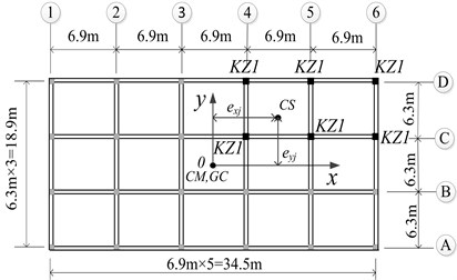
Fig. 2Plan view of the simplified model
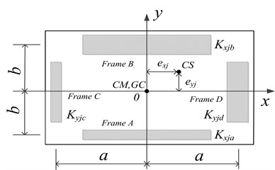
The slab of each floor is supported by two massless, axially inextensible load-resisting members in the and directions, respectively. The two frames parallel to the direction are labeled frame A and frame B, which are formed by combining the frames at the direction of the original structure of floor towards both sides; the two frames parallel to the direction are labeled frame C and frame D, which are formed by combining the frames at the direction of the original structure of floor towards both sides. Frame A and frame B are located at equal distance from, but on opposite sides of, -axis, providing the total translational stiffness of floor in the direction; Frame C and frame D are located at equal distance from, but on opposite sides of, -axis, providing the total translational stiffness of floor in the direction. , , , and are the lateral stiffness of each frame of floor .
The calculation of simplification model of floor can be expressed by a simultaneous equation group given in Eq. (1). That is, , , , , and can be calculated in Eq. (2):
in which, and are the lateral stiffness of the th column of floor in the and directions, respectively; and designate the and co-ordinates of the th column of floor ; and represent the total translational stiffness of floor in the and directions, respectively; is the torsional stiffness about the mass centre of floor . The coordinates of the stiffness center (CS) of floor are (, ). As in multistorey buildings, the centre of rigidity cannot be exactly defined, an approximate CS of floor is computed herein for reference purposes, , . The normalized stiffness eccentricities of floor are defined as , .
It is clear from Eqs. (1) and (2) that and of floor of the original model do not vary during the elastic stage, thus, and also do not vary. As a result, and of floor of the simplified model remain constant. When the structure enters the inelastic stage, and vary with the external load, and correspondently, and will also vary. It is evident that when conducting inelastic analysis by using a simplified model in replace of the original structure, the values of and can be adjusted so that the simplified model can be used to accurately replace the original model for inelastic analysis.
2.2. Simplified model of soil-eccentric structure interaction system
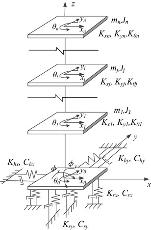
As shown in Fig. 3, the soil-structure interaction of torsionally coupled system consists of an -storey three-dimensional eccentric superstructure founded on a rigid foundation, which in turn, is supported by the horizontal and rotational springs that correspond to the horizontal and rotational degrees of freedom of the foundation. The stiffness coefficients of the springs represent the corresponding confining stiffness of the supporting soil to the foundation. The mass of the footing is concentrated at the center with its value is . Two orthogonal principal axes ( and ) of the footing can be defined through the mass center of the footing, and the vertical axis () passes through the mass center which is taken to be coincident with its geometric center. Five displacement degrees of freedom of the foundation slab are considered in this system. and are the translational degrees of freedom in the x and y directions, respectively; denotes the twist angle around the vertical axis; and designate the rocking rotations in the and planes of the foundation, respectively. The stiffness coefficients of the horizontal springs in the two primary axis directions are and , respectively; and represent the stiffness coefficients of the rotational springs in the and planes, respectively. Moreover, , , ,and are the damping coefficients of the dampers. The mass moment of inertia of the footing slab about the vertical axis is ; and denote the mass moment of inertia of the footing slab with respect to the and axes, respectively. Furthermore, is the mass of floor ; is the mass moment of inertia of the floor being equal to and denotes the radius of gyration of floor ; , and are the -translation and -translation with respect to the two principal horizontal axes and the -rotation about the vertical axis of the superstructure, respectively. and are the mass moments of inertia of floor with respect to the y and x axes, respectively. The height of the mass center of the foundation to the th floor slab is .
Fig. 3Schematic diagram of soil-structure interaction of torsionally coupled system
2.3. Motion equation of the soil-eccentric structure interaction system
For the soil-structure interaction system shown in Fig. 3, the motion equations of the entire system can be derived by the Lagrange energy method [21] according to the kinetic energy, potential energy, and non-conservative force-work equations of the system. Limited by space, the motion equation of the soil-three storey bidirectional eccentric structure interaction system under an earthquake ground motion in the direction is given as:
in which and are respectively the mass matrix and stiffness matrix of the superstructure [23]:
and is the displacement vector of the superstructure which is relative to the foundation displacement :
and have the same forms with and , respectively. And the expressions of and can be obtained by changing the letter “” in and to “”, respectively.
2.4. Solving the equation of motion for the interaction system
In a soil-structure interaction system, the modal damping ratio of foundation soil normally ranges between 15 %-20 %, which is much higher than the damping ratio of the superstructure which is between 3 %-5 %. The damping matrix of the entire system can be constructed from the damping of the foundation soil and the structure obtained through Rayleigh damping. However, this damping matrix cannot be solved through conventional modal analysis method because it is non-proportional damping. Both superstructure and foundation soil undergo proportional damping when they are considered separately. For this reason, the coupled term in the equation of motion for the soil-structure interaction system is moved to the right side of the equation as an external load to decouple the superstructure from the foundation soil using modal analysis. This method is called forced decoupling method which can reduce the number of equations and facilitate finding the superstructural seismic response solution.
The process of solving the equation of motion for the interaction system is as follows:
Eq. (3) can be further written in open form as Eqs. (4) and (5):
Thus, the Fourier transform is applied to Eqs. (4) and (5), and the following results can be obtained:
Based on the assumption that the fixed base structure possesses classical normal modes, the natural frequencies and mode shapes satisfy the following orthogonality conditions [24]:
where and ( 1-9) are the natural frequencies and damping ratios, respectively.
The structural seismic response in the complex frequency domain can be expressed in terms of the mode shapes as:
Introducing the transformation of Eq. (9) and applying the orthogonality conditions, Eq. (6), when premultiplied by , becomes:
where and are defined as:
is the modal structure transfer function, the modal displacement can then be solved from Eq. (10) as:
Substituting Eqs. (9) and (13) into Eq. (7), the expression of foundation seismic response can be obtained, and Eq. (7) can be written as:
where:
can be solved from Eq. (14);
Substituting into Eq. (13), and then substituting Eq. (13) into Eq. (9), the structural seismic response in complex frequency domain can be obtained.
Damping in soil involves multiple problems, and the parametric analysis is the main purpose of this paper. So the soil damping adopts stiffness-proportional damping, defined by . Soil damping is assumed to be in direct proportion only to the linear portion of stiffness, denoted , i.e. 0. is given by , where is the first natural frequency of the foundation and , at approximately 0.17, is the corresponding damping ratio [25].
3. Analysis methods
3.1. Selection and calculation of model parameters
The upper model in this study is an imaginary 5×3 span three storey homogenous bidirectional eccentric frame structure with a span of m and m, respectively. The plan view is shown in Fig. 1. The story height is m. The columns in Fig. 1 marked as KZ1 have a dimension of 0.5 m×m, and there are 6 in total. The sectional dimensions of the other frame columns are m×m, and there are 18 in total. Due to the asymmetric distribution of the columns, the distribution of stiffness is unsymmetrical both about the -axis and the -axis, thus the system has biaxial stiffness eccentricities. Moreover, there is no variation in each column along the vertical direction. That is, the superstructure investigated herein is a regular asymmetric building. The corresponding simplified model of the superstructure is acquired according to the approach specified in Section 2.1. The bilinear hysteretic model as shown in Fig. 4 is utilized to simulate the force-displacement relationship of each lateral load-resisting member-both in the and directions. denotes the stiffness of the member in the elastic stage; designates the stiffness after yielding, taken as 10 % of the elastic stiffness [26]; and is the yield displacement, which can be calculated according to empirical equations [27].
Fig. 4Bilinear restoring force model for each lateral-load resisting member
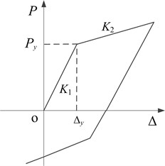
Fig. 5Schematic diagram of the analytical model of the foundation and its supporting soil
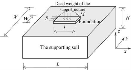
Three types of soil are considered in this paper. And their physical properties are normally described by the elastic modulus , density , and Poisson’s ratio . The physical properties of each soil analyzed in this study are listed in Table 1. In order to acquire the confining stiffness of the supporting soil to the foundation, the finite element analysis software ANSYS is used to establish the analytical model of the foundation and its supporting soil using the approach specified in study [21]. The analytical model is shown in Fig. 5. The supporting soil is fixed at the bottom, and the supporting effect of surrounding unbounded soil is simulated by imposing viscous-elastic boundary elements in the perimeter of the soil [28]. The dimension of the supporting soil on each side of the foundation is taken as three times of the foundation dimension in the same direction, and the depth is taken as twice the foundation width, that is, , , . The dead weight of the superstructure is applied on the top surface of the foundation, and the natural settlement of the soil is simulated. The constitutive relation of the soil is simulated by multi-linear kinematic hardening in ANSYS [29]. The hysteresis curve and skeleton curve of the confining stiffness of the supporting soil to the foundation is acquired by a cyclic loading. The least square method is adopted to fit the skeleton curve into a bi-fold line.
Limited by space, the acquired elastic and inelastic confining stiffness of the supporting soil 1 to the foundation and the corresponding yield displacement or yield rotational angle are listed in Table 2, and the bi-fold line of the horizontal confining stiffness in the direction of the soil 1 to the foundation is given in Fig. 6.
Fig. 6The bi-fold line of the horizontal confines stiffness in the x direction of the soil 1 to the foundation
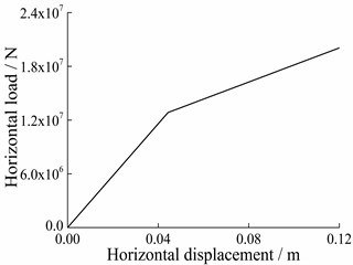
Table 1Properties of the soil considered in this study
Type of soil | (MPa) | (kg/m3) | |
Soil 1 | 6.0 | 1900 | 0.40 |
Soil 2 | 27.8 | 1950 | 0.40 |
Soil 3 | 41.4 | 1970 | 0.40 |
Table 2Confining stiffness of the supporting soil 1 to the foundation and the respective yield displacement and swing angle
Soil 1 | Confining stiffness in elastic stage | Confining stiffness in inelastic stage | Yield displacement (m) | Yield swing angle (rad) |
(N/m) | 2.051×10⁸ | 9.532×10⁷ | 0.0416 () | |
(N/m) | 2.128×10⁸ | 1.120×10⁸ | 0.0403 () | |
(N.m/rad) | 6.143×10¹⁰ | 2.294×10¹⁰ | 0.00186 () | |
(N.m/rad) | 2.691×10¹⁰ | 1.058×10¹⁰ | 0.00275 () |
3.2. Analysis by load incremental method
Before nonlinear static analysis, the free vibration motion equation for the entire system is derived by the Lagrange energy method when the structural displacement is absolute displacement:
in which , , is the structural absolute displacement:
The meanings of other parameters refer to Section 2.3.
The inverted triangular static loads along the direction are applied at the mass centers of the analytical model in a step-by-step manner using Matlab programming. The stiffness of each member is modified according to its displacement and restoring force model of the lateral load-resisting member at each step, and the confining stiffness of the foundation slab in each direction is also examined in order to see if it yields according to its translational displacement or rotational angle. The stiffness matrix of the system is subsequently modified and extracted for the next step analysis. Under the th step of load increment, the equilibrium equation of the system can be represented as:
is the stiffness matrix of the system calculated according to the displacement and restoring force model of the member and the confining stiffness of the supporting soil to the foundation after the step of load. The initial stiffness matrix of the system is taken during the calculation of the first load step, is the incremental displacement vector at the CMs under the th load increment. It is noted that is the absolute displacement increment, is the th incremental applied load vector.
The structural relative displacement increment at the th step can be calculated by subtracting the structural horizontal displacement due to the translational movement and the rotation of the foundation slab from :
is the structural relative displacement at the th step, is the initial structural relative displacement. The calculating equation of the relative displacement of the th member of floor under the th step is as follows:
Thus, the non-synchronization of the displacement of the members, which is caused by the torsion of the floor, can be considered in detail during the analysis. When the inter-story displacement angle of any floor reaches 1/50 specified by the Code for Seismic Design of Buildings (GB50011-2010)[8], the loading stops.
3.3. Inter-story restoring force model
For ease of inelastic parametric analysis, the inter-story restoring force model of the system needs to be determined. Using the calculated relationship of inter-story shear – inter-story displacement of floor , the trilinear idealization model is demonstrated in Fig. 7. The bilinear model adopted by the members and the effect of slab rotation on yield of each member make the curve of inter-story shear-inter-story displacement exhibit trilinear characteristics. The parameters to be determined for the trilinear idealization model of floor include the inter-storey stiffness of the three stages , and , the first turn and the second turn , which all can be determined by the study [30]. In practice, in order to acquire the inter-story restoring force model of the superstructure, a few more load steps may be required. During parametric analysis hereafter, a 1/50 displacement angle for any floor of the superstructure is still used as the limit value.
Fig. 7Schematic diagram of equivalent three-linear restoring force model
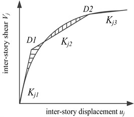
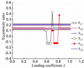
Fig. 8Variation of eccentricities with λ
3.4. Definition of analysis stages
Fig. 8 presents the variation of and ( 1, 2, 3) with the loading coefficient . is defined as the ratio of the load already applied on the system after each step to the final total load applied on the system with its maximum being one. The initial normalized stiffness eccentricities of the superstructure are 0.1344 and 0.2082. The variation curves of with have no mutation points, indicating that the members perpendicular to the load direction from the first floor to the third floor do not yield. Conversely, mutation points appear on the variation curves of and with , suggesting that the members in the load direction on the first and second floors yield in turns. Moreover, remains a straight line with , which indicates that the members parallel to the load direction on the third floor do not yield.
Variation of with is given in Fig. 9. It is clear from Fig. 9 that the variation curve of the soil 1-structure interaction system has a mutation point, suggesting that the translational confining stiffness in the direction of the soil 1-structure interaction system’s foundation enters into the inelastic stage. However, the confining stiffnesses in other directions are still in elastic stage when the loads stop. The confining stiffnesses in each direction of the systems situated on other soils are all in elastic stage when the loads stop.
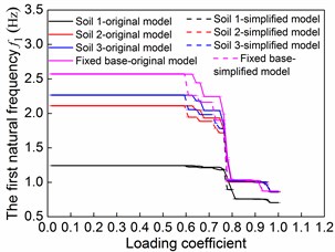
Fig. 10 shows the variation of the first order natural frequency with for the soil-original model interaction system and the soil-correspondent simplified model interaction system. It is clear from Fig. 10 that during the entire loading process, the variation curve of first order natural frequency of the soil-original model system matches favorably with the soil-simplified model system of the same soil type, and there are only minor differences during the yielding process of some structural lateral load-resisting members. Fig. 10 suggests that the parametric analysis for soil-eccentric structure interaction system using a simplified model for superstructure is both reliable and suitable for inelastic stage analysis. It is indicated that the reduction of the natural frequencies from elastic to inelastic is in a step-shaped manner and divides its variation process into three relatively stable stages. The stable variation of the natural frequencies reflects stable variation of the structural stiffness.
Fig. 9Variation of translational displacement x0 of the foundation with λ
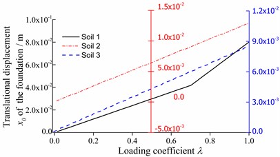
Fig. 10Variation of the first order natural frequency with λ
According to inelastic development of the superstructure, as well as the yield development of the translational confining stiffness in the direction of the soil 1-structure interaction system, some typical stages are chosen to conduct the parametric analysis.
1) The first stage: none of the members yield. The inter-story stiffness is taken as , and the confining stiffness of each soil type is taken as the elastic value.
2) The second stage: the inter-story stiffness in the load direction of floor one reaches , whereas those of the second and third floors remain as and . The confining stiffness of each soil type is still taken as the elastic value.
3) The third stage: the inter-story stiffnesses parallel to the load direction reach and of floor one and floor two, respectively. It is still for floor three. The translational confining stiffness in the direction of soil 1-structure interaction system enters into the inelastic stage, while the confining stiffnesses in the other directions remain in the elastic stage.
Here, the following parametric analyses only consider the elastic stage of the members perpendicular to the load direction. Apart from soil 1, the confining stiffness in each direction of other soil conditions remains in the elastic stage. The inter-storey stiffness of each floor in each stage together with other parameters of the entire system in that stage are substituted into the stiffness matrix so as to determine the stiffness matrix in each stage, and parametric analysis of frequencies in each stage can be carried out. The stiffness matrix is substituted again into Eq. (3), and the equation of motion in each stage is achieved. The equation of motion in each stage can be solved by Eqs. (4-14), and parametric analysis of seismic responses in each stage can be carried out.
3.5. Calculation of the mode direction factors
The main vibration mode of lateral-torsional coupling vibration mode can be determined by the mode direction factors when the structure’s bottom is fixed [31]. For a specific vibration mode, it is called the translational vibration mode when the torsional factor is less than 0.5, or it is called the torsional vibration mode when it is larger than 0.5. When the mode direction factor is equal to 1, the vibration mode is the pure translational vibration mode or pure torsional vibration mode. The translational factor in the direction, the translational factor in the direction, and the torsional factor for the th vibrating mode of a fixed base torsionally coupled structure can be calculated as:
For a soil-structure interaction of torsionally coupled system analyzed in this study, the above formulae cannot be used directly because the two rotational degrees of freedom of the foundation slab and are not taken into considered in them. The following modifications are applied to Eq. (19) in order to incorporate the foundation’s rotational degrees of freedom so that they can be utilized to analyze the soil- eccentric structure interaction system:
in which , , and are the displacement components in the th vibration mode of the th mass point in a regularized vibrating mode vector space; , ,, and are the displacement components in the th vibration mode of the foundation slab; and are the corresponding rotational factors. Table 3 shows the first three mode direction factors of the vibration mode in a soil-structure interaction of torsionally coupled system.
Table 3The mode direction factors of the first three orders (i= 1-3)
Mode | Sum | |||||
1 | 0.6891 | 0.1890 | 0.1124 | 0.0067 | 0.0028 | 1 |
2 | 0.2714 | 0.6602 | 0.0542 | 0.0030 | 0.0112 | 1 |
3 | 0.0293 | 0.1331 | 0.8339 | 0.0005 | 0.0032 | 1 |
It can be seen from Table 3 that the modified calculating formulae of the mode direction factors are reasonable and can be adopted for analyzing a soil-eccentric structure interaction system. It is also apparent from Table 3 that the first vibration mode of the system is primarily translational movement in the x direction, coupled with translational movement in the direction and torsion. The second vibration mode is mainly translational movement in the direction, coupled with the translational movement in the direction and torsion. Additionally, the third vibration mode is chiefly torsion coupled with translational movement in the and directions. In the below parametric analysis, the uncoupled torsion to lateral frequency ratio and the stiff eccentricities are introduced as the two main parameters. is defined as the ratio of the first order pure torsional frequency to the first order pure translational frequency in the direction of the corresponding fixed base torsionally uncoupled system. Primarily, the effects of uncoupled torsion to lateral frequency ratios and the normalized stiffness eccentricities on the normalized frequencies , , and seismic responses are evaluated. , and are the first three natural frequencies of the soil-structure interaction of torsionally coupled system. , and are the first order pure translational frequency in the x direction, the first order pure translational frequency in the direction, and the first order torsional frequency of the soil-structure interaction of torsionally uncoupled system, respectively.
4. Parametric analysis
Parametric analyses with different values of , and are carried out in this chapter. The range of is 1.0 to 1.8, and the range of and is 0.1 to 0.4. The normalized stiffness eccentricity is caused by an uneven distribution of the lateral load-resisting members parallel to the load direction, and is formed by an uneven distribution of the lateral load-resisting members perpendicular to the load direction. Lines of G1, G2, and G3 represent that , and are equal to one, respectively. A set of simplified models can be established by using the approach specified in study [23].
4.1. Parametric analysis of the normalized frequencies
4.1.1. Effects of and soil
The effects of and soil on , and are presented in this subsection. and are kept constant at 0.2.
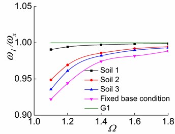
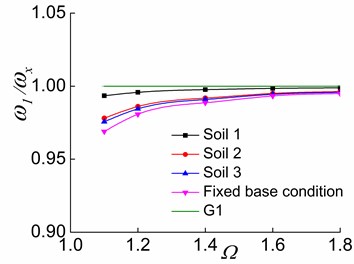
Fig. 11The effects of Ω and soil on ω1/ωx in the three stages
a) The first stage
b) The second stage
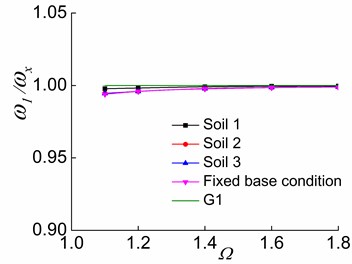
c) The third stage
The variations of and with are displayed in Figs. 11-13, respectively. It is evident from the figures that increasing causes to approach G1 (Fig. 11). This finding demonstrates that increasing leads to a weak lateral-torsional coupling effect in the first order mode and makes approach . That is, the first vibration mode of the system is close to the first pure translational vibration mode in the direction of the soil-corresponding equivalent symmetric structure interaction system. In other words, the translational deformation component in the direction in the structural response will gradually increase, and the coupled torsional deformation component will decrease. The structural response will be near the first order pure translational in the direction of a soil-structure interaction of torsionally uncoupled system.
Fig. 12The effects of Ω and soil on ω2/ωy in the three stages

a) The first stage
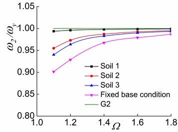
b) The second stage
c) The third stage
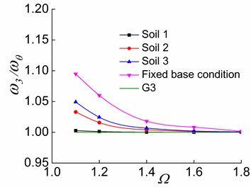
Fig. 13The effects of Ω and soil on ω3/ωθ in the three stages
a) The first stage
b) The second stage
c) The third stage
Furthermore, the increase of causes and toapproach G2 and G3, respectively (Figs. 12-13), suggesting that and respectively approach and as increases. This indicates that the system with a larger value has a larger torsional stiffness and a weaker lateral-torsional coupling effect. For systems situated on soil 2 and soil 3, as the soil softens, , and more closely approach G1, G2, and G3, respectively. This demonstrates that the soil-structure interaction of torsionally coupled system reduces the lateral-torsional coupling effect. The softer the soil of the interaction system is, the weaker the lateral-torsional coupling effect is. As a result, , and respectively approach , and as increases and as the soil softens.
4.1.2. Effects of and soil
The effects of and soil on the normalized frequencies , and are presented in this subsection. and are kept constant at 0.2 and 1.4, respectively.
Fig. 14The effects of by and soil on ω1/ωx in the three stages

a) The first stage
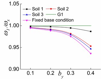
b) The second stage
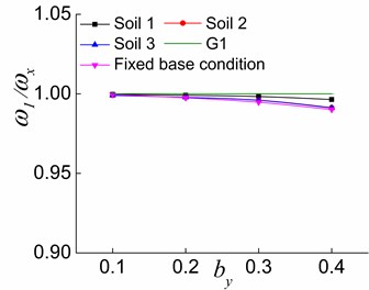
c) The third stage
The variations of , and with situated in different soil conditions are illustrated in Figs. 14-16, respectively. As it can be seen, increasing causes to deviate from G1 (Fig. 14). Moreover, is close to G2 in the first and second stages (Fig. 15(a) and (b)) and is farther from G2 in the third stage (Fig. 15(c)) with the increase in . The increase of causes to shift away from G3 in the first stage (Fig. 16(a)). In the second stage, increasing by leads to firstly approaching and then shifting away again from G3 for the fixed base condition and makes deviate from G3 for the interaction system (Fig. 16(b)). In the third stage, moves nearer to G3 with the increase of (Fig. 16(c)). The results reveal that the increased improves the lateral-torsional coupling effect of the first order vibration mode of the soil-torsionally coupled system, and deviates from . That is, the first vibration mode of the system deviates from the first pure translational vibration mode in the direction of the soil-corresponding equivalent symmetric structure interaction system. In other words, the translational deformation component in the direction in the structural response will reduce, and the coupled torsional deformation component will increase. The structural response will be close to the first torsional response of the soil-torsionally uncoupled system. It is worth mentioning that the effects of increasing on and are different at the second and third stages. The larger is in the elastic stage, the closer is to , and the farther is from . As inelastic develops, the larger is, the farther is from , and the closer is to . Moreover, the softer the soil of the interaction system is, the closer the variation curve is to 1, which demonstrates that the softer the soil of the interaction system is, the weaker lateral-torsional coupling effect is.
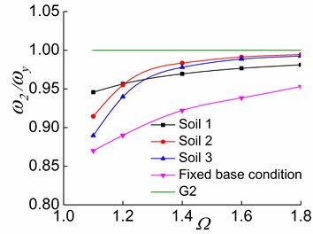
Fig. 15The effects of by and soil on ω2/ωy in the three stages
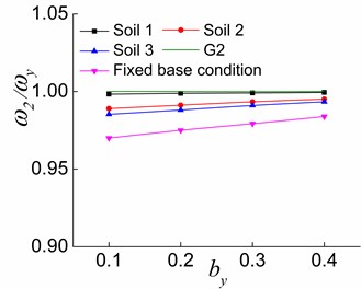
a) The first stage
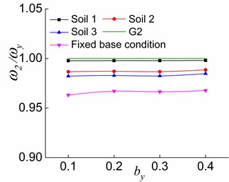
b) The second stage
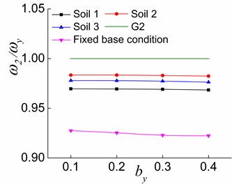
c) The third stage
For systems situated on soil 2, soil 3 and fixed base condition, the effects of structural inelastic development on , and are identical, and the only differences are the values. It is clear from Figs. 11-16 that gets more close to G1 (Figs. 11 and 14), is far from G2 (Figs. 12 and 15), and is first close to then deviate from G3 (Figs. 13 and 16) during the process from the first stage to the second stage and then to the third stage of a system. The above finding is due to the fact that the yielding of the lateral load-resisting members in the direction leads to the reduction of the structure’s overall lateral stiffness in the direction, and the lateral-torsional coupling effect of the first order vibration mode is weakened. As a result, is close to . A greater value and a smaller value lead to a greater reduction in the effects of and on . The reduction of the overall torsional stiffness is not pronounced in the second stage, and is slightly closer to . Nevertheless, the overall torsional stiffness is also significantly reduced in the third stage, which causes to deviate from . The lateral stiffness in the direction does not change because the lateral load-resisting members in this direction are in the elastic stage. With the reduced lateral stiffness in the load direction, the coupled translational component in the direction in the second vibration mode reduces while the corresponding torsional component increases. In other words, deviates from .
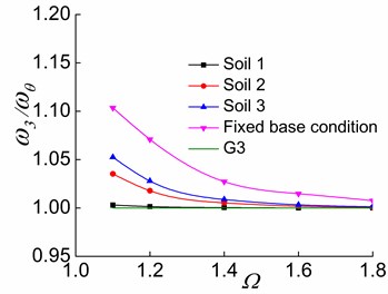
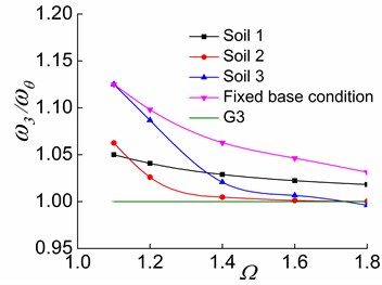
Fig. 16The effects of by and soil on ω3/ωθ in the three stages
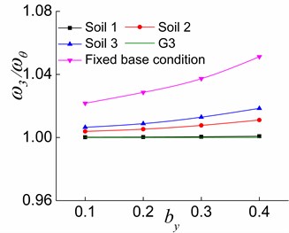
a) The first stage
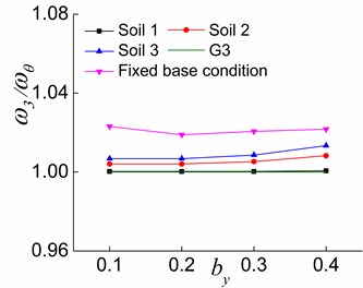
b) The second stage
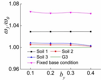
c) The third stage
Variations of and with or of soil 1-structure interaction system in the third stage are significantly different from those of the system situated on other soils. In the third stage, the increase of makes and approach G2 and G3, respectively. However, the variation is less significant than in the cases with other soil types. The deviation distances between and G2 as well as and G3 are larger than those of other soil conditions when is slightly larger than 1.4. However, they do not indicate that the lateral-torsional coupling effects are stronger in the second and third vibration modes of the soil 1-structure interaction system. Instead, they signify the fact that the vibration modes of the soil 1-eccentric structure interaction system change. For example (0.2), in the third stage of a soil 1-eccentric structure interaction system with 1.1, the main mode direction factors of the second and third vibration modes are 0.0500, 0.9455 and 0.9267, 0.0517, respectively. Additionally, they are respectively 0.0311, 0.9680 and 0.9461, 0.0318 of the system with 1.8. Moreover, in the third stage of a soil 2-structure interaction system with 1.8, the main mode direction factors of the second and third vibration modes are 0.9713, 0.0115 and 0.0111, 0.9882, respectively. The above data suggest that the second and third order vibration modes of the soil 1-structure interaction system respectively change to the torsional vibration mode and the translational vibration mode in the direction in the third stage compared to other soil conditions. This is because that in the third stage, the yielding of the members in the direction and the translational confining stiffness in the direction of the soil 1-structure interaction system lead to a considerable reduction in the overall lateral stiffness and overall torsional stiffness of the system. However, the lateral stiffness in the direction does not change because the lateral load-resisting members in this direction are all in the elastic stage. As a result, the second and third order vibration modes of the soil 1-structure interaction system respectively change to the torsional vibration mode and the translational vibration mode in the y direction. This is obviously different from the systems situated on soil 2 and soil 3. It is also clear that the influences of and on the lateral-torsional coupling effects of the vibration modes are considerably reduced in the soil 1-structure interaction system compared to the systems situated on soil 2 and soil 3.
4.2. Parametric analysis of the structural seismic responses
The ratio of the superstructural displacements in complex frequency domain at the mass centre of each floor to Fourier transform of the ground motion displacement, denoted , is referred to as the displacement transfer function. As the ratio reflects the dynamic response of the system under unit harmonic excitation, the transfer function can represent the structural dynamic response when given the same input.
and are respectively the translational displacement transfer functions in the and directions of the first floor; is the torsional displacement transfer function of the first floor.
, , are their respectively peak values. And the effects of and on, , are mainly studied in this section (Unless otherwise noted, “displacement” in this section means the peak value of the bottom displacement transfer function).
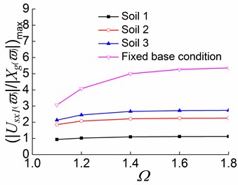
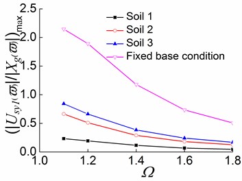
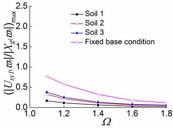
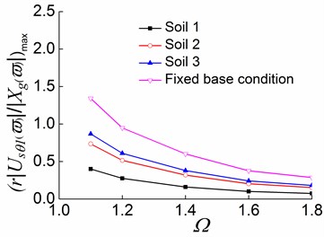
4.2.1. Effects of on the peak values of displacement transfer functions (0.2)
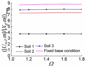
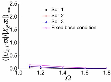
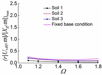
The variations of the peak values of displacement transfer functionswith in different stages are illustrated in Figs. 17-19, respectively. The following conclusions can be drawn from Figs. 17-19:
1) With the softening of the foundation soil, the peak values of displacement transfer functions decrease, and the curves tend to be gentler. For example, in the first stage of the soil -eccentric structure interaction systems with 1.4, the translational displacements in the direction of the systems situated on soil 1, soil 2, and soil 3 are respectively 78.0 %, 55.7 %, and 46.6 % lower than that on the fixed base condition. This suggests that the flexibility of the foundation soil decreases the structural seismic response of an interaction system, and the softer the foundation soil, the greater the reduction ratio.
2) For systems situated on different soils and the fixed base condition, the translational displacement in the direction slowly increases with the adding of in the first stage, and the displacement variation is very small when is approximately greater than 1.2. Accordingly, the translational displacement in the direction and the torsional displacement decrease with the increase in . It follows that with the increase of , the structural seismic response is getting more and more close to the pure translation in the direction, and the coupled torsional displacement and the translational displacement in the direction become progressively small.
3) In the second and third stages, the translational displacement in the direction under the three soil conditions show no noticeable variation pattern as increases, and the displacement variations are relatively small. The torsional displacement and the translational displacement in the y direction decrease slowly and gently with the increase of . The analysis results show that the effects of on the structural seismic responses are reduced as structural inelastic developments.
Fig. 17Peak values of displacement transfer functions against Ωin the first stage
a)
b)
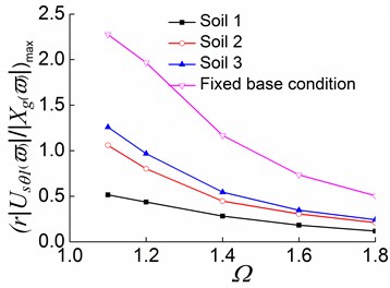
c)
Fig. 18Peak values of displacement transfer functions against Ωin the second stage
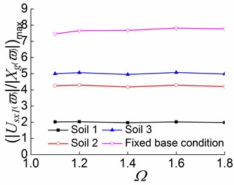
a)
b)
c)
4) In the first and second stages, the decrease rate of the torsional displacement with is related to the value of . When is approximately smaller than or equal to 1.2, the greater value of , the larger the decrease rate; when is greater than 1.2, the smaller value of , the larger the decrease rate. In the first stage, for a system situated on soil 1, the decrease percentages of torsional displacement are 15.3 %, 35.4 %, and 35.0% as increases from 1.1 to 1.2, from 1.2 to 1.4, and from 1.4 to 1.6, respectively. In the second stage, these decrease percentages are respectively 31.4 %, 41.7 %, and 36.4 %. This also demonstrates that the development of structural inelastic causes the torsional displacement to decrease more quickly with the increase of .
5) The effects of different foundation conditions on the structural seismic responses are also weakened by the development of structural inelastic. As a result, the responses of systems situated on different foundation conditions tend to be increasingly similar to the response of the fixed base condition, especially for the systems situated on soil 2 and soil 3. For example, when 1.4, the translational displacements in the direction under the conditions of soil 1, soil 2, and soil 3 decrease by 78.1 %, 55.7 %, and 46.6 %, respectively, compared to that of the fixed base condition in the first stage. In the second stage, the decrease percentages are 74.3 %, 45.6 %, and 35.5 %, respectively; the third stage see even smaller decreases at 57.3 %, 16.4 %, and 10.1 %, respectively.
Fig. 19Peak values of displacement transfer functions against Ωin the third stage
a)
b)
c)
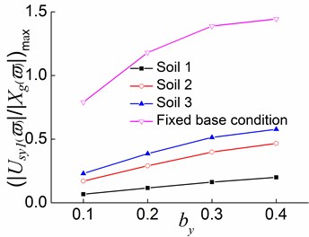
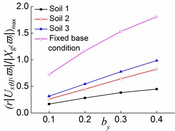
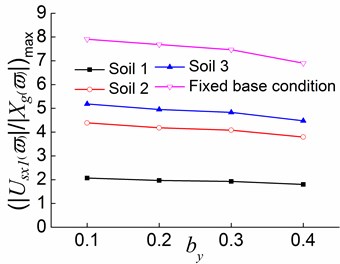
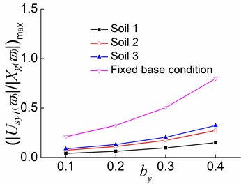
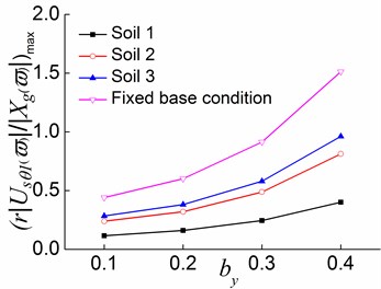
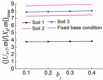
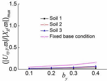
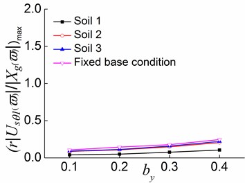
4.2.2. Effects of on the peak values of displacement transfer functions ( 1.4, 0.2)
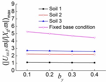
The variations of the peak values of displacement transfer functionswith in different stages are illustrated in Figs. 20-22, respectively. The following conclusions can be drawn from Figs. 20-22:
1) In the first stage, as increases, the translational displacement in the direction decreases, while the translational displacement in the direction and the torsional displacement increase. For systems on the fixed base condition, as increases from 0.2 to 0.3, the variation percentages of the translational displacement in the and directions, and the torsional displacement are respectively 5.9 %, 17.6 %, and 31.4 %. For systems situated on soil 2, the variation percentages are 1.1 %, 37.1 %, and 43.4 %, respectively. In addition, the variation of the translational displacement in the y direction for systems situated on soil 1 and soil 3 are respectively 40.0 % and 33.2 %. This demonstrates that when the soil-structure interaction is taken into account, an increase in has a smaller effect on the translational displacement along the load direction, and greater effects on the translational displacement perpendicular to the load direction and the torsional displacement. Moreover, decreasing soil hardness can enhance the effect of increasing on the translational displacement perpendicular to the load direction.
Fig. 20Peak values of displacement transfer functions against by in the first stage
a)
b)
c)
2) In the second stage, the translational displacement in the direction still decreases with the increase of , and the translational displacement in the direction and the torsional displacement also increase with . When is approximately greater than or equal to 0.2, increasing exerts greater effects on the translational displacements in both directions and torsional displacement in the second stage than in the first stage. For the systems situated on soil 1, as increases from 0.3 to 0.4, the variation percentages of the translational displacement in the and directions, and the torsional displacement are respectively 1.0 %, 22.6 %, and 17.3 % in the first stage. In the second stage, the magnitudes of these changes increase to 6.6 %, 53.5 %, and 63.5 %, respectively.
3) The translational displacement in the direction increases slightly with the increase of , and the translational displacement in the direction and the torsional displacement also increase with the adding of in the third stage. Compared to the second stage, this stage sees smaller magnitudes of changes in displacements, especially in the translational displacements along the two directions. For the systems situated on soil 1 in the second stage, an increase in from 0.2 to 0.3 results in 2.2 %, 54.9 %, and 52.6 % changes in the translational displacement along the , directions, and the torsional displacement, respectively. In the third stage, the magnitudes of these changes are respectively 0.6 %, 26.0 %, and 50 %.
Fig. 21Peak values of displacement transfer functions against by in the second stage
a)
b)
c)
The variations of the peak values of displacement transfer functions of the first floorwith in different stages are also analyzed. Analysis results show that increasing can result in a decrease in the translational displacement along the load direction, as well as a relatively significant increase in the translational displacement perpendicular to the load direction. The effect of on the torsional displacement is associated with foundation hardness. Increasing causes an increase in the torsional displacement when the foundation soil is relatively hard, and it causes a decrease as the foundation soil becomes soft. This suggests that when the foundation soil is relatively soft, increasing can reduce the torsional displacement.
The variations of the peak values of displacement transfer functions of the second and third floorswith , and in different stages are also analyzed. Combined with the parametric analysis of the normalized frequencies, it can be seen that is getting more and more close to during the process from the first stage to the second stage and then to the third stage of a system, and the lateral-torsional coupling effect in the first vibration mode is significantly reduced. Accordingly, the translational displacement in the direction of the first floor gradually increases and the translational displacements in the direction of the second and third floors decrease. Furthermore, the translational displacement in the direction and the torsional displacement also gradually decrease. The above finding is due to the fact that the lateral load-resisting members in the x direction of floor one firstly yield in the second stage and further yield in the third stage. The yielding of the members leads to a considerable reduction on the overall lateral stiffness in the direction of floor one. As a result, the lateral stiffness in the direction of floor one becomes increasingly weak compared to other floors. Therefore, the displacement response in the direction of floor one becomes increasingly larger, while those of other floors become less significant. The overall structural seismic response gradually approaches the pure translation in the x direction, and the coupled torsional displacement and the translational displacement in the direction become increasingly smaller. The coupling effect between the translation in the direction and the torsion is substantially reduced.
Fig. 22Peak values of displacement transfer functions against by in the third stage
a)
b)
c)
5. Conclusions
The aim of this paper is to present a new method to investigate the lateral-torsional coupling behaviours of soil-multistorey structure interaction of torsionally coupled system through the whole process from the elastic stage to inelastic stage under external load. The impacts of the uncoupled torsion to lateral frequency ratios and the stiffness eccentricities on the first three natural vibration frequencies and structural seismic response of the eccentric structure situated on different soils are analyzed. Results show that the lateral-torsional coupling behaviours of the system in the elastic stage vary significantly compared to those in inelastic stage. And the variations of the system with parameters in different stages are remarkably different. Soil hardness can significantly affect the structural seismic response. Some specific conclusions are drawn as follows:
1) The soil can significantly reduce the lateral-torsional coupling effect and the structural seismic response of the soil-bidirectional eccentric structure interaction system as compared with the fixed base condition. The softer the soil is, the larger the reduction is. A smaller value and larger values of and lead to a larger reduction in the lateral-torsional coupling effects of the first order mode from the first stage to the nonlinear inelastic stage. The effects of different foundation conditions on the structural seismic responses are also weakened by the development of structural inelastic. And the responses of the systems situated on different foundation conditions tend to be increasingly similar to the response of the fixed base condition.
2) A smaller value, larger values of the and , and a softer foundation soil lead to a larger reduction in the influences of and eccentricities on lateral-torsional coupling effect compared with the fixed base condition.
3) For systems situated on soil 1, soil 2, soil 3 and fixed base conditions, a large indicates that the system has a larger torsional stiffness and a weaker lateral-torsional coupling effect. The translational displacement in the direction gradually increase, and the coupled torsional displacement and the translational displacement in the y direction become progressively small.
4) Increasing can result in a decrease in the translational displacement along the load direction, as well as a relatively significant increase in the translational displacement perpendicular to the load direction. The effect of increasing on the torsional displacement is associated with foundation hardness. Increasing can reduce the torsional displacement when the foundation soil is relatively soft.
5) Increasing strengthens the lateral-torsional coupling effect of the first vibration mode and weakens the lateral-torsional coupling effect of the second vibration mode in the first stage. For systems situated on soil 2, soil 3 and fixed base conditions. The effects of increasing on and are different at the second and third stages. In the elastic stage, the larger is, the closer is to , and the farther is from . As inelastic develops, the larger is, the farther is from , and the closer is to . However, for a system situated on soil 1, increasing causes to deviate from in the third stage. After considering the soil-structure interaction, an increase in has a smaller effect on the translational displacement along the load direction, and greater effects on the translational displacement perpendicular to the load direction and the torsional displacement. Moreover, decreasing soil hardness can enhance the effect of increasing on the translational displacement perpendicular to the load direction.
6) The overall lateral stiffness and the torsional stiffness of the soil 1-eccentric structure system are weak, as a result, the effects of , , on the lateral-torsional coupling effects is significantly reduced as compared with other soils. In the third stage, the second and third order vibration modes of the soil 1-eccentric structure system shift to the torsional vibration mode and the translational vibration mode in the direction, respectively.
7) is getting more and more close to during the process from the first stage to the second stage and then to the third stage of a system, and the lateral-torsional coupling effect in the first vibration mode is significantly reduced. Accordingly, the overall structural seismic response gradually approaches the pure translation in the direction, and the coupled torsional displacement and the translational displacement in the direction become increasingly smaller. The coupling effect between the translation in the direction and the torsion is substantially reduced.
References
-
Bugeja M. N., Thambiratnam D. P., Brameld G. H. The influence of stiffness and strength eccentricities on the inelastic earthquake response of asymmetric structures. Engineering Structures, Vol. 21, Issue 9, 1999, p. 856-863.
-
Esteva L. Earthquake engineering research and practice in Mexico after the 1985 earthquakes. Bulletin of the New Zealand National Society for Earthquake Engineering, Vol. 20, Issue 3, 1987, p. 159-200.
-
Mitchell D., Tinawi R., Redwood R. G. Damage to buildings due to the 1989 Loma Prieta earthquake – a Canadian code perspective. Canadian Journal of Civil Engineering, Vol. 17, Issue 5, 1990, p. 813-834.
-
Halabian A. M., BirzhandiM. S. Inelastic response of bi-eccentric plan asymmetric reinforced concrete buildings. Proceedings of the Institution of Civil Engineers – Structures and Buildings, Vol. 167, Issue 8, 2014, p. 469-485.
-
Rizwan S. M., Singh Y. Effect of strength eccentricity on torsional behaviour of RC frame buildings. Journal of the Institution of Engineers (India): Series A, Vol. 93, Issue 1, 2012, p. 15-26.
-
Cai Xian-hui, Wu Rui-feng, Qu Nai-si Research on seismic response of one type of asymmetrical multistorey buildings. Earthquake Engineering and Engineering Vibration, Vol. 19, Issue 4, 1999, p. 55-60, (in Chinese).
-
Goel R. K., Chopra A. K. Inelastic seismic response of one-storey, asymmetric-plan systems: effects of stiffness and strength distribution. Earthquake Engineering and Structural Dynamics, Vol. 19, Issue 7, 1990, p. 949-970.
-
Code for Seismic Design of Buildings (GB50011-2010). China Architecture and Building Press, Beijing, 2010, p. 40, (in Chinese).
-
Halabian A. M., EI Naggar M. H. Effect of non-linear soil-structure interaction on seismic response of tall slender structures. Soil Dynamics and Earthquake Engineering, Vol. 22, Issue 8, 2002, p. 639-658.
-
Dutta S. C., Bhattacharya K., Roy R. Response of low-rise buildings under seismic ground excitation incorporating soil-structure interaction. Soil Dynamics and Earthquake Engineering, Vol. 24, Issue 12, 2004, p. 893-914.
-
Rodriguez M. E., Montes R. Seismic response and damage analysis of buildings supported on flexible soils. Earthquake Engineering and Structural Dynamics, Vol. 29, Issue 5, 2000, p. 647-665.
-
Bao Y., Ye G., Ye B., et al. Seismic evaluation of soil-foundation-superstructure system considering geometry and material nonlinearities of both soils and structures. Soils and Foundations, Vol. 52, Issue 2, 2012, p. 257-278.
-
Sáez E., Lopez-Caballero F., Modaressi-Farahmand-Razavi A. Inelastic dynamic soil-structure interaction effects on moment-resisting frame buildings. Engineering Structures, Vol. 51, 2013, p. 166-177.
-
Balendra T., Tat C. W., Lee S. L. Modal damping for torsionally coupled buildings on elastic foundation. Earthquake Engineering and Structural Dynamics, Vol. 10, Issue 5, 1982, p. 735-756.
-
Tsicnias T. G., Hutchinson G. L. Soil-structure interaction effects on the steady-state response of torsionally coupled buildings. Earthquake Engineering and Structural Dynamics, Vol. 12, Issue 2, 1984, p. 237-262.
-
Sikaroudi H., Chandler A. M. Structure-foundation interaction in the earthquake response of torsionally asymmetric buildings. Soil Dynamics and Earthquake Engineering, Vol. 11, Issue 1, 1992, p. 1-16.
-
Sivakumaran K. S., Balendra T. Seismic analysis of asymmetric multistorey buildings including foundation interaction and P-Δ effects. Engineering Structures, Vol. 16, Issue 8, 1994, p. 609-624.
-
Wu W. H., Wang J. F., Lin C. C. Systematic assessment of irregular building-soil interaction using efficient modal analysis. Earthquake Engineering and Structural Dynamics, Vol. 30, Issue 4, 2001, p. 573-594.
-
Shakib H., Fuladgar A. Dynamic soil-structure interaction effects on the seismic response of asymmetric buildings. Soil Dynamics and Earthquake Engineering, Vol. 24, Issue 5, 2004, p. 379-388.
-
Çelebi E., Gündüz A. N. An efficient seismic analysis procedure for torsionally coupled multistory buildings including soil-structure interaction. Turkish Journal of Engineering and Environmental Sciences, Vol. 29, Issue 3, 2005, p. 143-157.
-
Jiang Xin-liang, Wang Mei-li, Wang Xue-yan Range of parameters and its performance research on torsional coupling of soil-asymmetric structure interaction system. Engineering Mechanics, Vol. 26, Issue 3, 2009, p. 73-78, (in Chinese).
-
Li Y., Jiang X. L. Parametric analysis of eccentric structure-soil interaction system based on branch mode decoupling method. Soil Dynamics and Earthquake Engineering, Vol. 48, 2013, p. 63-70.
-
Jiang X. L., Kuang Y. P. Inelastic parametric analysis of two-way asymmetrical multi-storey buildings. Advances in Structural Engineering, Vol. 19, Issue 5, 2016, p. 806-824.
-
Wu W. H., Smith H. A. Efficient modal analysis for structures with soil-structure interaction. Earthquake Engineering and Structural Dynamics, Vol. 24, Issue 2, 1995, p. 283-299.
-
Zhao Hui-fang Research on Dynamical Behavior of Soil-structure Nonlinear Interaction System Considering Spatial Effect. Tianjin University, Tianjin, 2005, p. 22-23, (in Chinese).
-
Zhang Xin-pei Non-linear Analysis of Reinforced Concrete Aseismic Structures. Sciense Press, Beijing, 2003, p. 23-26, (in Chinese).
-
He Zheng, Ou Jin-ping Non-linear Analysis of Reinforced Concrete Structure. Harbin Institute of Technology Press, Harbin, 2007, p. 248-249, (in Chinese).
-
Gu Yin, Liu Jing-bo, Du Yi-xin 3D consistent viscous-spring artificial boundary and viscous-spring boundary element. Engineering Mechanics, Vol. 24, Issue 12, 2007, p. 31-37, (in Chinese).
-
Huo Yi Parametre Analysis on the Seismic Behavior of Soil-asymmetric Structure Interaction System. Tianjin University, Tianjin, 2006, p. 13-35, (in Chinese).
-
Jeing J. C., Hideo Moritaka, Ikuo Shimoda Kagoshima airport terminal building seismic retrofit – 3D inelastic analysis of structure with viscous damper system. Building Structure, Vol. 30, Issue 6, 2000, p. 19-22., (in Chinese).
-
Technical Specification for Concrete Structures of Tall Building (JGJ 3-2010). China Architecture and Building Press, Beijing, 2011, p. 214-215, (in Chinese).
About this article

This work was financially supported by the National Science Foundation Project (Research Project No. 51278335), National Youth Science Foundation Project (Research Project No. 51208356) and the National Science Foundation Project (Research Project No. 51478312), China.
