Abstract
In the paper plane vibrations of an elastic circular structure are analyzed. Investigations of a two dimensional problem are performed. It is assumed that vibrations are taking place. Several first eigenmodes are investigated. Results obtained by using the experimental procedure of stroboscopic geometric moiré are analyzed. By applying the superimposed moiré technique, the results are investigated. Different numbers of gaps are used and provide results of different quality.
1. Introduction
In this paper plane vibrations of an elastic circular structure are analyzed. Investigations of a two dimensional problem are performed. It is assumed that vibrations are taking place. Several first eigenmodes are investigated. Results obtained by using the experimental procedure of stroboscopic geometric moiré are analyzed. By applying the superimposed moiré technique, the results are investigated. Different numbers of gaps are used and provide results of different quality.
This paper continues the analysis of superimposed moiré techniques and of vibrations of circular structures. Similar problems are analyzed in [1-10] and in a number of other similar papers.
2. Theoretical description of superimposed moiré for circular structures
Angular moiré lines are represented as:
where and are the coordinates of a point of a two dimensional structure in the status of equilibrium, determines the width of angular moiré lines, is the intensity of the image painted on the surface of the structure.
Radial moiré lines are represented as:
where determines the width of radial moiré lines, is the intensity of the image painted on the surface of the structure.
Superimposed moiré lines are represented as:
where is the intensity of the image painted on the surface of the structure.
In the earlier papers the special function of the following type was introduced:
where 0, 1, 2,… determines the gap between the moiré lines, determines the width of moiré lines.
Angular moiré lines with gaps are represented as:
Radial moiré lines with gaps are represented as:
3. Conventional stroboscopic geometric moiré images of vibrating circular elastic structure
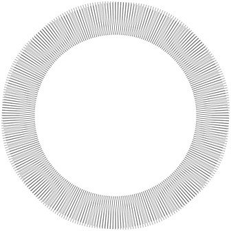
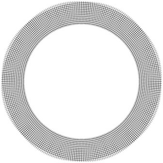
Investigations of a circular elastic structure are performed. It is assumed that the internal radius of the circular structure is fixed. Stroboscopic geometric moiré images for the angular and radial directions of fringes for the eighth eigenmode are shown.
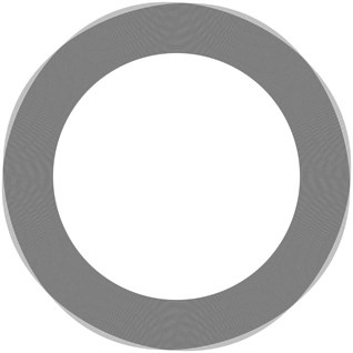
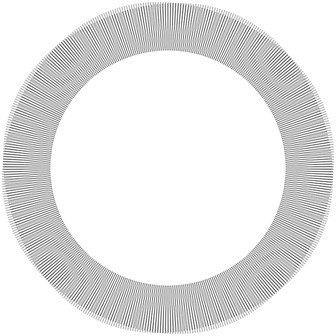
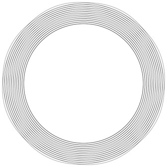
When there are no gaps (that is the gap width is 0) the images are represented in Fig. 1. When there is a single gap (that is the gap width is 1) the images are represented in Fig. 2. When there is a double gap (that is the gap width is 2) the images are represented in Fig. 3.
4. Superimposed moiré images of vibrating circular elastic structure
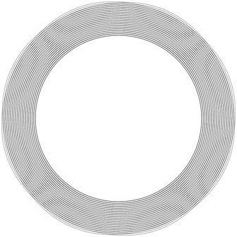
The eighth eigenmode is investigated. Results are obtained by using superimposed stroboscopic geometric moiré.
When there are no gaps (that is the gap width is 0) the images are represented in Fig. 4. When there is a single gap (that is the gap width is 1) the images are represented in Fig. 5. When there is a double gap (that is the gap width is 2) the images are represented in Fig. 6.
Fig. 1Problem without gaps
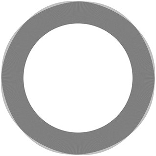
a) Angular fringes
b) Radial fringes
The obtained results of investigations indicate that it is a great problem to perform the interpretation of the image when the problem is without gaps. And when there are greater gaps the number of obtained moiré fringes decreases. This has a negative effect to the accuracy of the performed measurements. From the obtained results it is possible to provide recommendations for the choice of the number of gaps. Acceptable results when 1 are obtained.
Fig. 2Problem with a single gap
a) Angular fringes
b) Radial fringes
Fig. 3Problem with a double gap
a) Angular fringes
b) Radial fringes
Fig. 4Problem without gaps
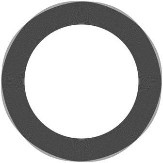
Fig. 5Problem with a single gap
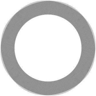
Fig. 6Problem with a double gap
5. Theoretical investigation of the stroboscopic measurement of vibrations for black and white (not grayscale) lines
This investigation is based on the use of the one dimensional model. In the previous paper when performing the analysis by using the one dimensional model the assumption was made that the intensity of lines changes smoothly according to the law of cosine squared. But in many engineering applications the lines are black and white. Thus here the one dimensional model corresponding to the problem when the lines are black and white is investigated.
The following special function is introduced:
For the case when the displacements are negative moiré lines are:
where is the displacement, is the intensity of the image. Thus:
where is a constant.
For the case when the displacements are positive moiré lines are:
where is the displacement, is the intensity of the image. Thus:
The stroboscopic image has the usual representation of intensity:
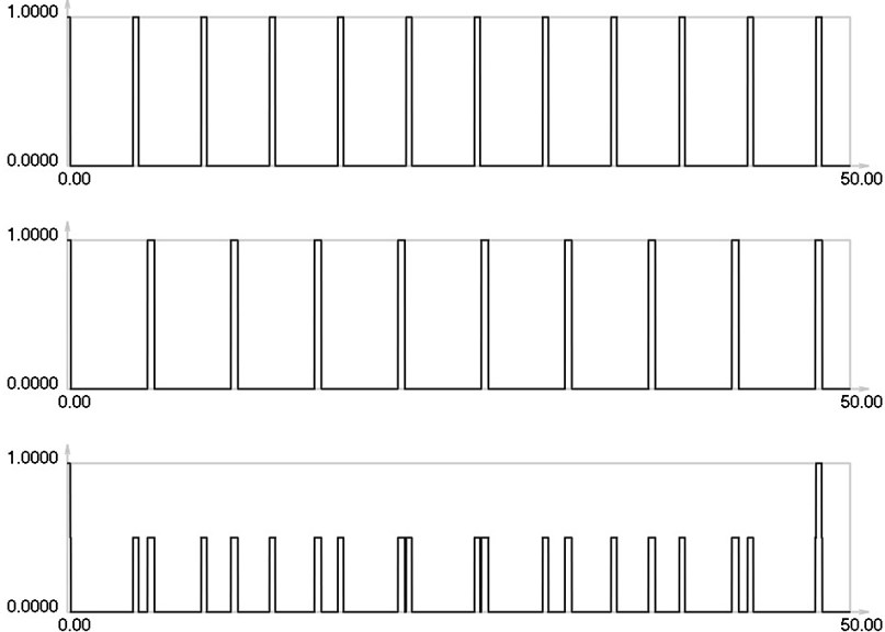
In the performed investigation parameters have the values: and .
, and for are graphically shown in Fig. 7.
Fig. 7I1, I2 and Is for i= 0: 13 maximums in the envelope of the stroboscopic image
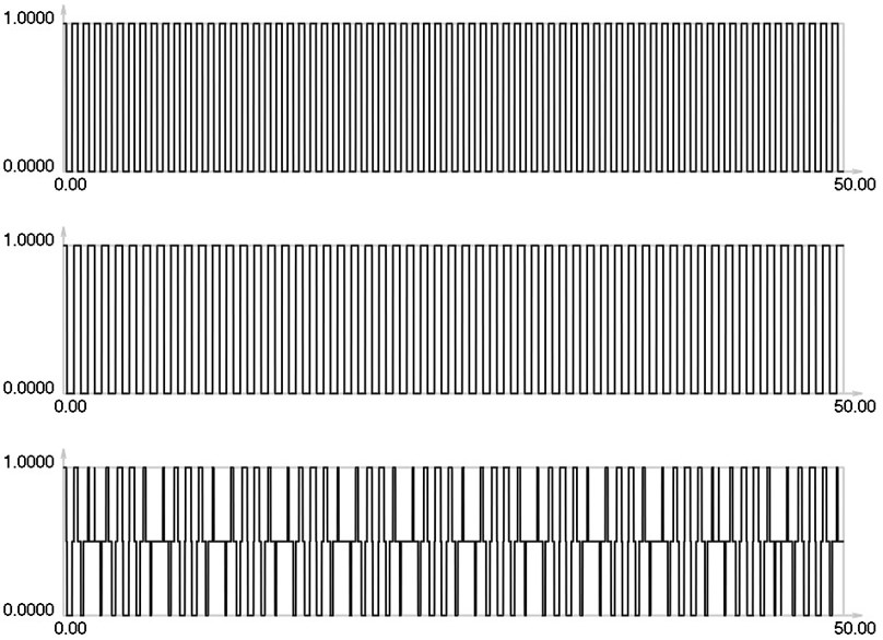
Fig. 8I1, I2 and Is for i= 1: 7 maximums in the envelope of the stroboscopic image
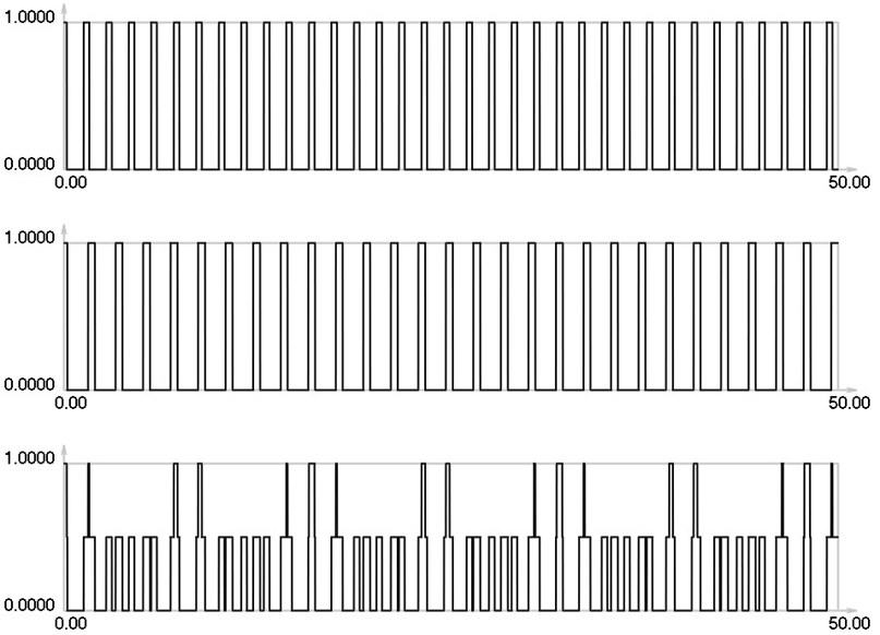
Fig. 9I1, I2 and Is for i= 2: 5 maximums in the envelope of the stroboscopic image
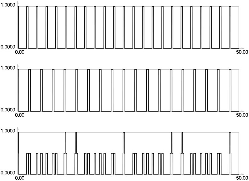
Fig. 10I1, I2 and Is for i= 3: 4 maximums in the envelope of the stroboscopic image
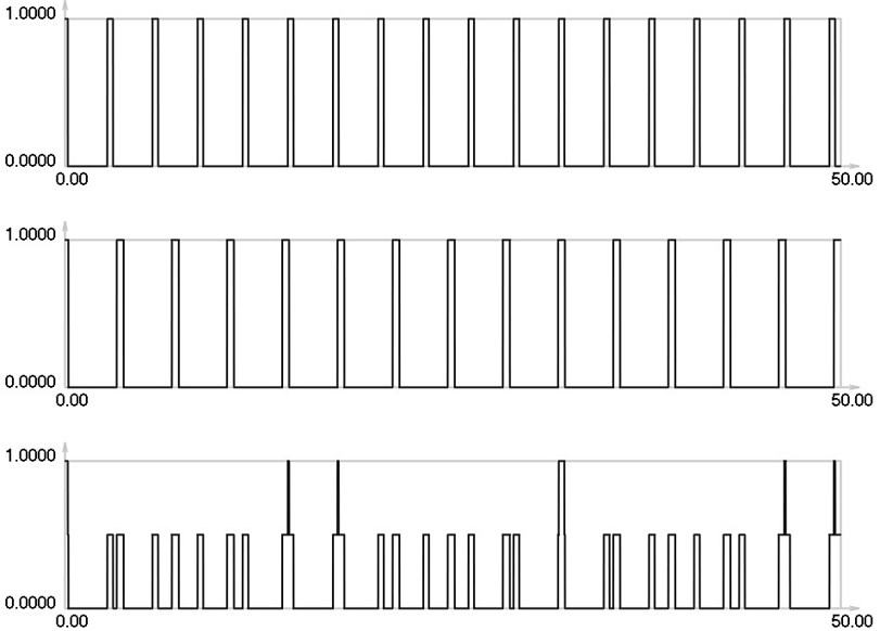
Fig. 11I1, I2 and Is for i= 4: 2 maximums in the envelope of the stroboscopic image
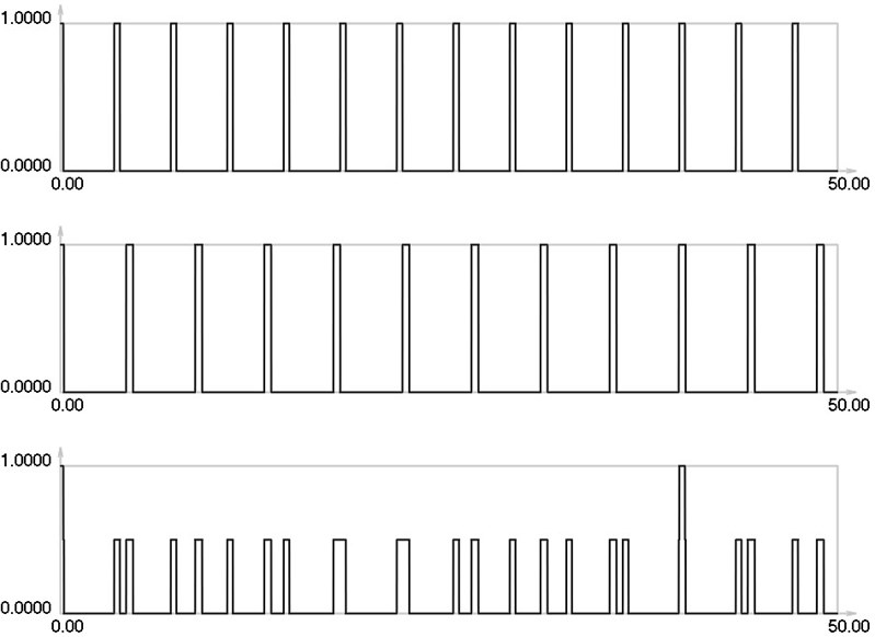
Fig. 12I1, I2 and Is for i= 5: 2 maximums in the envelope of the stroboscopic image (distance between the observed maximums is greater than when i= 4)
, and for are graphically shown in Fig. 8.
, and for are graphically shown in Fig. 9.
, and for are graphically shown in Fig. 10.
, and for are graphically shown in Fig. 11.
I1, I2 and Is for are graphically shown in Fig. 12.
Thus one can see from the presented results that when the gap increases the intervals between the maximums of the envelope of final investigated images also increase. On the basis of this fact it is concluded that one can interpret the displacements by using moiré images that have gaps.
6. Conclusions
In the performed investigation based on the method of superimposed moiré both moiré images in the analyzed problem of a circular elastic structure in two dimensions performing plane vibrations are represented simultaneously.
The obtained results of investigations indicate that it is a great problem to perform the interpretation of the image when the problem is without gaps. And when bigger gaps are used accuracy of measurement decreases. From the obtained results it is possible to provide recommendations for the choice of the number of gaps. Acceptable results when 1 are obtained.
Theoretical investigation of the one dimensional problem when the lines are black and white is performed. This is true in a number of engineering applications. From the obtained graphical relationships, it is concluded that one can interpret the displacements by using moiré images that have gaps.
The obtained results are used for the analysis and measurement of vibrations of mechanical devices, especially when high precision is required.
References
-
Huimin X., Guotao W., Fulong D., Guangjun Z., Xingfu L., Fangju Z., Aiming X. The dynamic deformation measurement of the high speed heated LY12 aluminium plate with moiré interferometry. Journal of Materials Processing Technology, Vol. 83, Issues 1-3, 1998, p. 159-163.
-
Deason V. A., Epstein J. S., Abdallah A. Dynamic diffraction moiré: theory and applications. Optics and Lasers in Engineering, Vol. 12, Issues 2-3, 1990, p. 173-187.
-
Kokaly M. T., Lee J., Kobayashi A. S. Moiré interferometry for dynamic fracture study. Optics and Lasers in Engineering, Vol. 40, Issue 4, 2003, p. 231-247.
-
Timoshenko S. P., Goodier J. N. Theory of Elasticity. Nauka, Moscow, 1975.
-
Soifer V. A. Computer processing of images. Herald of the Russian Academy of Sciences, Vol. 71, Issue 2, 2001, p. 119-129.
-
Vest C. Holographic Interferometry. Mir, Moscow, 1982.
-
Han B., Post D., Ifju P. Moiré interferometry for engineering mechanics: current practices and future developments. Journal of Strain Analysis for Engineering Design, Vol. 36, Issue 1, 2001, p. 101-117.
-
Field J. E., Walley S. M., Proud W. G., Goldrein H. T., Siviour C. R. Review of experimental techniques for high rate deformation and shock studies. International Journal of Impact Engineering, Vol. 30, Issue 7, 2004, p. 725-775.
-
Dai F. L., Wang Z. Y. Geometric micron moiré. Optics and Lasers in Engineering, Vol. 31, Issue 3, 1999, p. 191-198.
-
Liang C. Y., Hung Y. Y., Durelli A. J., Hovanesian J. D. Time-averaged moiré method for in-plane vibration analysis. Journal of Sound and Vibration, Vol. 62, Issue 2, 1979, p. 267-275.
About this article
The authors thank the reviewers for their valuable comments which enabled to improve the paper.
