Abstract
A full scale structural vibration and noise induced by flow was simulated by a hybrid numerical method. An interior flow field was solved by large eddy simulation firstly. The sliding mesh technique was applied to take into account the impeller-volute interaction. A sensitivity analysis on effects of near-wall grid size and sampling time on amplitude of pressure pulsations was performed to impose appropriate vibration exciting source. Computed modal of pump components was validated by experimental results, before the volute vibration and sound field were simulated using a coupled vibro-acoustic model. The numerical results indicated that the amplitude of pressure fluctuation, especially on those points located at near the volute tongue, strongly depended on near-wall grid size. The dominated frequency of the vibration velocity of volute was also blade-passing frequency (BPF), which was in according with frequency spectral characteristics of unsteady pressure fluctuation. Directivity distribution of radiation acoustic field excited by volute vibration was typical dipoles. This study shows that it is feasible to use the hybrid numerical method to evaluate the flow-induced vibration and noise generated in centrifugal pump.
1. Introduction
Centrifugal pump is a rotating machine in which flow and pressure are generated. It is thus expected that the fluid transport is accompanied with as little vibration and noise as possible. In centrifugal pump, pressure fluctuations attributed to the interaction between impeller and volute, interact with the volute casing and generate dynamic effects (mainly unsteady forces) on both stationary and rotating pump components [1], which are one of the primary excitation sources of vibration and hydraulic noise [2, 3]. So, the investigation on pressure fluctuations and flow-induced vibration and noise in centrifugal pumps is of continuous interest.
In the past decades, many experimental and numerical studies on unsteady pressure pulsations in centrifugal pumps have been carried out. Chu [4, 5] et al. (1995a, b) showed by experiments that interactions of non-uniform out-flux from the impeller with the tongue can be major contributors to noise generation within the volute of a centrifugal pump. Dong [2] et al. studied the effect of modifications to tongue and impeller geometries on the flow field structure and resulting noise in a centrifugal pump by experiment. Kaupert [6] et al. measured the unsteady pressure field inside the impeller of a centrifugal pump using piezo resistive pressure transducers and a telemetry system. These experimental investigations have provided valuable insight into understanding the nature of such unsteady flow, but it is usually tedious, time-consuming and expensive. Moreover, because of complex geometry, it is not possible to carry out a thorough investigation of the flow field for a vast number of operating conditions [7]. As the advent of supercomputers and the development of computational method, the direct numerical solution of governing equations makes even more attractive technique. Several numerical studies have been reported in the technical literature on unsteady interactions and pressure fluctuations in centrifugal pump [8-11]. For example, Barrio [8] et al. presented a numerical study on the unsteady flow behavior near the tongue region for a centrifugal pump, and major focused on the relation between the pressure pulsations and the fluctuating velocity field. Majidi [11] predicted unsteady pressure distribution in the impeller and volute casing, and found that fluctuation amplitude was strong at impeller outlet and at the vicinity of the tongue.
Pressure fluctuations interact with the volute casing and generate hydraulic excitation forces on pump components, which can be give rise to fatigue fractures of pump components [12]. Khalifa [13] et al. studied the unsteady pressure field and flow-induced vibration phenomenon by experiments and concluded that it is difficult to rely on measurements at discharge and suction pipes to identify pump vibration that is correlated to the internal pressure fluctuations and occurred at the same blade-passing frequencies. Jiang [14] et al. studied flow-induced mechanical vibrations and noise by using a weakly coupled method in a multi-stage centrifugal pump. In the simulations, the feedback influences of environmental noise generated by vibration on the structure were neglected. Wang and Liu [15] et al. studied the effects of impeller outlet angles and width on flow induced vibration and noise of centrifugal pumps by experimental measurement and numerical simulation respectively. Although, these investigations have provided valuable insight into understanding the relationship between the unsteady pressure pulsations and flow-induced vibration and noise, many other issues, including sensitivity of flow excitation force, fluid-structural-acoustic coupled investigation and reducing the vibration and noise technique etc., are not deeply understand.
In this paper, the main goal is to investigate structural vibrations and noise characteristics induced by flow in centrifugal pump based on a coupled vibro-acoustic model. Therefore, the flow excitation force must be credible for obtaining reliable vibration and noise characteristics. But for our problem, the excitation force is from the turbulence flow inside the pump, which is complicated and nonlinear. The precision of the results is strongly affected by several numerical parameters. So, a sensitivity analysis on effects of near-wall grid size and sampling time on amplitude of pressure pulsations was firstly investigated to impose appropriate vibration exciting source. Moreover, computed modal of pump components was validated by experimental results, before the volute vibration and sound field were simulated using a coupled vibro-acoustic model.
The contents are organized as follows. Unsteady flow field is simulated using LES method with sliding mesh technique in Section 2. Section 3 describes vibration and noise induced by flow including mathematical model and numerical results. Some concluding remarks are contained in Section 4.
2. Flow simulation
The centrifugal pump model considered in this study has a shrouded impeller with six backswept blades. The blade profile varies between the hub and the shroud. The blade angle at the inlet varies from 15 deg at the shroud to 28 deg at the hub. The blade angle at the outlet is 30 deg. The flow from impeller is discharged into a vaneless volute casing that is designed according to the theory of a constant average velocity for all sections of the volute. The main dimensions and characteristics of the pump are presented in Table 1.
2.1. Governing equations
Fluid flow inside a centrifugal pump is generally considered as complex three-dimensional turbulent flow. In this paper, the flow field inside the pump was solved by using large eddy simulation (LES) to catch the detailed characteristics of the unsteady flow. In LES, the three-dimensional time dependent large-scale turbulent motion was resolved directly and the effect of the unresolved (or subgrid) scales was taken into account by appropriate subgrid-scale (SGS) models [16]. The governing equations describing the behavior of the large scales are as following:
where the over bars indicate the spatial filtering. is fluid density, and , and are velocity, pressure and viscosity of the fluid respectively. and are time and space coordinate, is the sub-scale stress modeling. The subscript and are the direction component of coordinate. The unsteady flow fields were simulated with the commercial code Fluent. Bounded central differencing method was used to solve Eq. (1). For the discretization in the time domain, the second-order implicit format was adopted. The pressure-velocity coupling was calculated by means of the SIMPLEC algorithm. Second-order format was used for pressure term. Prior to the unsteady flow calculations, steady simulations were carried out by using a so-called multiple reference frame model. When achieving convergence, the results of which were used as initial condition to unsteady flow simulations. For the unsteady calculation, 60 time steps were considered per blade-passing period with a time step of 5.74e-5 s, namely the time impeller rotated through one degree. For each time step, the convergence criterion was established in a value of 1e-5 for the scaled residuals, with at least 50 iterations per time step. The unsteady simulations were considered when the flow reached a clear periodic regime, with a minimum of 5 full impeller revolutions.
Table 1Main characteristics of the investigated pump
Impeller | ||
Impeller inlet diameter | (mm) | 97.5 |
Impeller outlet diameter | (mm) | 172 |
Impeller outlet passage width | (mm) | 20 |
Blade outlet angle | (o) | 30 |
Blade number | 6 | |
Volute casing | ||
Base circle diameter | (mm) | 178 |
Volute width at the base circle | (mm) | 35 |
Design point | ||
Volume flow rate | (m3/h) | 100 |
Total head | (m) | 30 |
Rotational speed | (rpm) | 2900 |
2.2. Computational domain and meshing
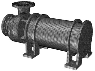
Fig. 1 shows some views of the pump numerical geometry domain that is composed of inlet duct, impeller, volute and outlet duct. Straight ducts at inlet and outlet are used to prevent boundary condition effects on simulation of the pump flow domain. Fig. 2 shows surface meshes including a general view of the pump with the inlet duct, impeller and volute and a detail of the volute tongue and boundary layer of blade surface. The mesh is hexahedral elements with a total number of about 7,920,000 cells.
2.3. Boundary conditions
The boundary conditions imposed were a constant total pressure at the inlet, and the spectral synthesizer, which based on the random flow generation technique originally proposed by Kraichnan [17] and modified by Smirnov et al. [18], was used to generate fluctuating velocity components. This boundary condition avoids the definition of a fixed velocity profile in inlet suction. Flow rate boundary condition at the outlet and the no-slip conditions over wall. The relative motion of the impeller module with respect to the pump was taken into account by means of the sliding mesh technique at the impeller-volute and impeller-inlet duct grid interfaces.
Fig. 13D models of total domain including: (i) inlet duct, (ii) impeller, (iii) volute and (iv) outlet duct
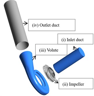
Fig. 2Computational mesh for the investigated pump
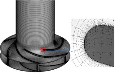
a) Surface meshes of inlet duct and impeller
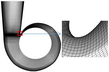
b) Surface meshes of volute
2.4. Numerical sensitivity analysis
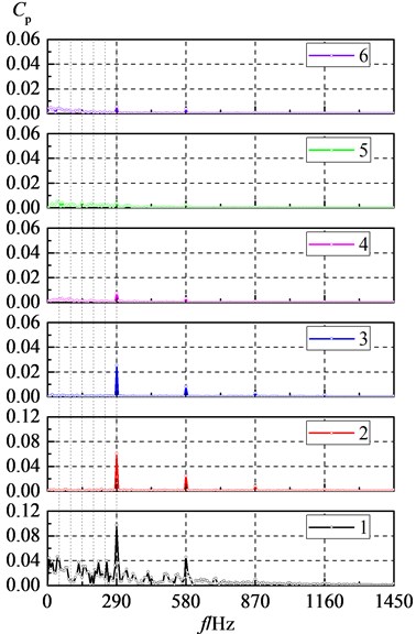
In the numerical resolution of the flow equations, the precision of the results as well as the required computation resources are strongly affected by several numerical parameters [19] including the grid size, the time step, sampling time and the turbulence model etc. Before imposing the definitive vibration exciting source, a sensitivity analysis was done by comparing their effects on the pressure pulsation amplitude at some measuring points in the volute wall region, whose positions were illustrated in Fig. 3.
Fig. 4 illustrates the pressure fluctuation amplitude of BPF (290 Hz) at sampled points 1-6 with different near-wall grid sizes corresponding to nominal flow condition, where the first layer grid height of near-wall was normalized by viscous sublayer thickness (0.046 mm) flows in the inlet duct when Reyonds number is 3.6e5. Pressure fluctuation amplitude was normalized by using the circumferential dynamic pressure at the impeller exit diameter, i.e. . It can be seen that the pressure pulsation amplitude of that point located at near the volute tongue strongly depends on near-wall grid size. And the amplitudes of BPF with respect to point 1 are shown as Table 2 with different near-wall grid sizes, from which it can be seen that it is reasonable to imposing accurate vibration exciting source if non-dimensional near-wall grid size 0.26.
Fig. 5 presents typical spectrums of the pressure pulsation that was sampled at point 1 with different sampling times, where is the time that impeller rotates through 360 degrees. The spectrum was obtained by a Fourier transform; from which it can be seen that the amplitude of BPF is less affected by sampling time. But it is noticed that those amplitudes of the other frequency especially low frequency pulsation are more dependent on sampling time. The shorter the sampling time, the lower frequency resolution, give rise to aliasing errors, which can amplify the amplitude of some low frequency pulsation. With the increase of sampling time, the amplitude of the low frequency pulsation is gradually decreased. So it is reasonable to capturing pressure fluctuation amplitude if sampling time is greater than 7 full impeller revolutions.
Table 2The pressure fluctuation amplitude of BPF with respect to B1 point with different h/δ
6.52 | 1.30 | 0.26 | 0.05 | |
0.0548 | 0.0789 | 0.0977 | 0.0998 |
Fig. 3Positions of the measurement points in the volute surface
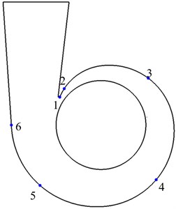
Fig. 4The pressure fluctuation amplitude of BPF at different monitoring points
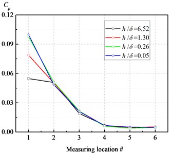
Fig. 5The spectrums of the pressure pulsation at point 1
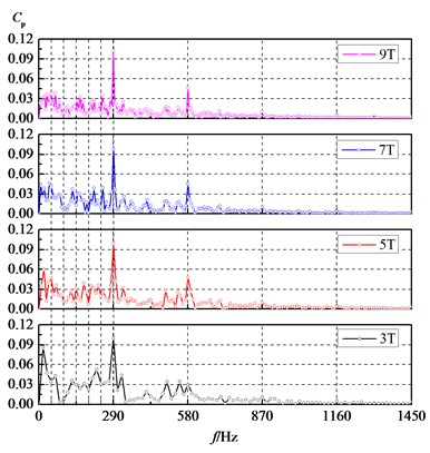
Fig. 6The spectrums of the pressure pulsation
2.5. Pressure fluctuations
Fig. 6 shows spectrums of the pressure pulsation that was sampled at points 1-6. The spectrum was obtained by a Fourier transform, from which it can be seen that the pressure pulsation is dominated by the BPF (290 Hz) and its harmonic components and gradually decreasing along the spiral volute, which indicates the interaction, between the impeller and volute, is major contributors to pressure fluctuations in the centrifugal pump. It is noticed that pressure fluctuation of shaft frequency is quite prominent near the volute tongue, whose amplitude is about 41 % of that of BPF, which is consistent with the observed phenomenon in experimental results [20]. But to other monitoring points, the pressure fluctuation amplitude of shaft frequency is insignificant, which is different from experimental results [20]. This discrepancy may be because of the unbalanced motion of the rotor enhancing the pressure fluctuations of the shaft frequency in experimental process, but being neglected in numerical simulation.
3. Vibration and noise simulation
Unsteady hydraulic excitation forces acting on the pump give rise to structural vibration and further radiate noise to the environment. The feedback of noise on the structure affects structural vibration characteristics simultaneously. In this study, the interaction process among the fluid, structure and noise are simulated by coupling way as follows: (i) 3D unsteady flow was solved by using LES method, which provided a time series for the pressure fluctuations at the fluid-structure interface. In the simulations, the feedback influence of structural vibration on the fluid was neglected. (ii) Structural vibration induced by the unsteady flow was simulated using finite element method, and the acoustic pressure generated by structural vibration was computed using boundary element method. The mutual coupling interaction between the structural vibration and the acoustic pressure field in the fluid were taken into account by using the vibro-acoustic coupling model. This provided the vibration velocities on the outer surface of volute. (iii) Noise emission to the environment was performed by using boundary element method.
3.1. Acoustic model
The governing equation for sound fields radiated by the volute vibration is Helmholtz equation:
where is the amplitude of the sound pressure fluctuation, is called the wavenumber. is the angular frequency and is the sound speed of the fluid.
In this study, Eq. (2) is solved by using boundary element method, which has been widely used in acoustics for computing the noise radiated from vibrating objects. For interior acoustic problem, boundary integral formulation equations with respect to Eq. (2) are shown as follows:
where and denote the sound pressure and normal velocity distribution on the close boundary surface respectively, and is mean fluid density. The symbol denotes the Green kernel function, which represents the free-field pressure in point due to a unit acoustic point source excitation in :
The leading coefficient in integral Eq. (3) is 1 for in the domain, 0 for in the exterior domain and, 1/2 for on a smooth boundary.
For numerical computation, the Helmholtz integral Eq. (3) is evaluated for each node on the boundary surface, which gives the following discretized equation:
where and are global coefficient matrix. For each collocation node, i.e. , this yields:
where is the kronecker delta function and, is the shape function.
To use direct boundary element method, the inlet and outlet are blocked with elements, the non-reflecting condition is used in the simulation. According to linear time-harmonic acoustic simulation rule, six linear elements per wavelength is required. For our volute BEM acoustic model, the maximum valid frequency is 8700 Hz. So the mesh is sufficiently fine for the BPF (290 Hz) harmonic acoustic analysis.
3.2. Vibration model
The finite element model for vibrations of structure takes the form:
where is a displacement vector, , , denote stiffness, damping and mass matrices of the structure respectively. is the force loading of the acoustic pressure on the structure along the fluid-structure coupling interface. The symbol represents fluid-structural coupling matrix which is given by:
where is the number of coupling surface elements. and are the structure mesh shape function and acoustic mesh shape function, respectively. The symbol is the unit normal vector. is the external flow excitation force load, applied normal to the fluid-structure interface, the expression of which is:
For coupled vibro-acoustic problems, the discretized boundary integrated Eq. (5) and finite element Eq. (7) must be solved by simultaneously to including the mutual coupling interaction between the acoustic pressure and the structural vibration. And at the fluid-structure interface, the fluid normal velocity values at the nodes of the acoustic mesh to the displacement components at the nodes of the structure mesh yield:
where is the transformation matrix.
Fig. 7 shows a full scale structure mesh, which has 0.58 million 4-noded tetrahedral elements. Different types of element and dimensions are applied for different parts in order to get the fined geometry features. The coefficients used are: Modulus of elasticity 210 GPa, density 7850 Kg/m3, Poisson ratio 0.3.
Fig. 7Mesh used in structural simulation
3.3. Numerical results
A full scale centrifugal pump structural vibration and noise induced by flow was simulated by LMS Virtual Lab software. Structural models, as shown in Fig. 8, are mainly composed of inlet and outlet flanges, volute, shaft and motor etc. The springs with the different stiffness coefficients are adopted to simulate the two components connections in centrifugal pump. Moreover, prior to coupled vibro-acoustic systems were solved, the analysis of vibrating modal of the centrifugal pump components was carried out. For validating the computed modal, the comparisons between the computed free modal models of pump components for first natural frequency and experimental results, provided by Shanghai Marine Equipment Research Institute, were performed, and they agreed well as shown in Table 3. Then, the constrained modes of the centrifugal pump which connected with the inlet/outlet pipe were calculated and fifty-order models were also imported into the acoustic solver. The former tenth-order modes of the volute were shown in Table 4.
Table 3Comparison of the FEM results with experiments for the 1st natural frequency
Components | Exps (Hz) | FEM (Hz) | Error (%) |
Volute | 911 | 888 | 2.5 |
Overall pump components | 282 | 281 | 0.3 |
Table 4Constrained modes of overall pump components
Order number | Frequency (Hz) | Order number | Frequency (Hz) |
1 | 128.18 | 6 | 343.89 |
2 | 154.28 | 7 | 363.71 |
3 | 184.43 | 8 | 384.88 |
4 | 282.95 | 9 | 617.03 |
5 | 301.85 | 10 | 686.75 |
Fig. 9 shows spectrums of the vibration velocity that was sampled at the points a-c shown in Fig. 8, from which it can be seen that the structural vibration is dominated by the BPF components and with smaller peaks appearing at the third shaft frequency, the second and third blade-passing frequencies, which is in according with frequency spectral characteristics of pressure fluctuation. The BPF vibrations arise from rotor-stator interactions. From Table 4, it can be seen that the forth-order mode frequency of pump is close to the BPF of pressure fluctuation, so it is concluded that resonance maybe occur at this frequency. The amplitude of vibration velocity gradually increases from inlet (point a) to output (point b) then to volute tongue (point c), which indicates that the interaction between impeller and volute tongue can be the major contributor to the vibration and noise generation within the volute of a centrifugal pump. Moreover, the BPF vibration characteristics are coincident with the experimental results [21], although discrepancies do exist at the low frequency components and the shaft frequency, which may be caused by the unbalance of the rotor is neglected and only the dynamic surface pressure on the walls is used in simulation.
Fig. 8The centrifugal pump structure model
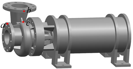
Fig. 9The spectrums of vibration velocity at points a-c
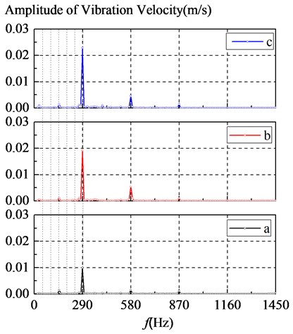
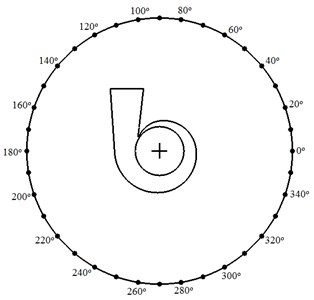
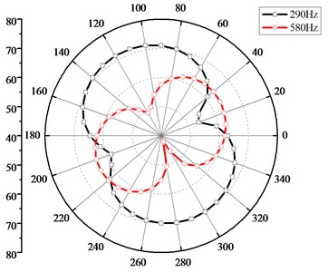
Fig. 10 illustrates thirty-sixth sound pressure monitors located at one meter away from the center of the pump and directivity distribution of outer radiation sound field induced by volute vibration corresponding to BPF and the second BPF respectively, from which it can be seen that directivity distribution of radiation acoustic field is typical dipoles. This is conforming to the fact that only the dynamic surface pressure (dipole source) is loaded and the monopole and quadrupole contributions of fluid-acoustic sources are neglected in the coupled simulation. The sound pressure level of radiation noise field excited by vibration is about 53-71 dB for BPF components and 42-63 dB for the second BPF respectively.
Fig. 10Monitoring points position and directivity distribution of radiation noise field
4. Conclusions
This study presented a structural simulation of flow-induced structural vibrations and noise of a single-suction volute type centrifugal pump. The vibration of the volute and sound field was solved based on a coupled vibro-acoustic model. The following results were obtained,
1) It is reasonable to imposing appropriate vibration exciting source and capturing pressure fluctuation amplitude if non-dimensional near-wall grid size 0.26 and sampling time greater than 7 full impeller revolutions.
2) The structural vibration is dominated by the BPF components and with smaller peaks appearing at the third shaft frequency, the second and third blade-passing frequencies, which is in according with frequency spectral characteristics of pressure fluctuation.
3) Directivity distribution of radiation acoustic field is typical dipoles when only the dynamic surface pressure was loaded.
References
-
Adkins D. R., Brennen C. E. Analysis of hydrodynamic radial forces on centrifugal pump impellers. ASME Journal of Fluids Engineering, Vol. 110, Issue 1, 1988, p. 20-28.
-
Dong R., Chu S., Katz J. Effect of modification to tongue and impeller geometry on unsteady flow, pressure fluctuations and noise in a centrifugal pump. ASME Journal of Turbomachinery, Vol. 119, Issue 3, 1997, p. 506-515.
-
González J., Fernández J., Blanco E., Santolaria C. Numerical simulation of the dynamic effects due to impeller-volute interaction in a centrifugal pump. ASME Journal of Fluids Engineering, Vol. 124, Issue 2, 2002, p. 348-355.
-
Chu S., Dong R., Katz J. Relationship between unsteady flow, pressure fluctuations and noise in a centrifugal pump. Part A: use of PIV data to compute the pressure Field. ASME Journal of Fluids Engineering, Vol. 117, Issue 1, 1995, p. 24-29.
-
Chu S., Dong R., Katz J. Relationship between unsteady flow, pressure fluctuations and noise in a centrifugal pump. Part B: effect of blade-tongue interaction. ASME Journal of Fluids Engineering, Vol. 117, Issue 1, 1995, p. 30-35.
-
Kaupert K. A., Staubli T. The unsteady pressure field in a high specific speed centrifugal pump impeller. Part I: influence of the volute. ASME Journal of Fluids Engineering, Vol. 121, Issue 3, 1999, p. 621-626.
-
Shojaeefard M. H., Tahani M., Ehghaghi M. B., Fallahian M. A., Beglari M. Numerical study of the effects of some geometric characteristics of a centrifugal pump impeller that pumps a viscous fluid. Computers and Fluids, Vol. 60, 2012, p. 61-70.
-
Barrio R., Parrondo J., Blanco E. Numerical analysis of the unsteady flow in the near-tongue region in a volute-type centrifugal pump for different operating points. Computers and Fluids, Vol. 39, Issue 5, 2010, p. 859-870.
-
Croba D., Kueny J. L. Numerical calculation of 2D, unsteady flow in centrifugal pumps: impeller and volute interaction. International Journal for Numerical Methods in Fluids, Vol. 22, Issue 6, 1996, p. 467-81.
-
Wang H., Tsukamoto H. Experimental and numerical study of unsteady flow in a diffuser pump at off-design conditions. ASME Journal of Fluids Engineering, Vol. 125, Issue 5, 2003, p. 767-778.
-
Majidi K. Numerical study of unsteady flow in a centrifugal pump. ASME Journal of Turbomachinery, Vol. 127, Issue 2, 2005, p. 363-371.
-
Breugelmans F. A. E., Sen M. Prerotation and fluid recirculation in the suction pipe of centrifugal pump. Proceedings of the 11th Turbomachinery Symposium, Texas A&M University, 1982, p. 165-180.
-
Khalifa A. E., Al-Qutub A. M., Ben-Mansour R. Study of pressure fluctuations and induced vibration at blade-passing frequencies of a double volute pump. Arabian Journal for Science and Engineering, Vol. 36, Issue 7, 2011, p. 1333-1345.
-
Jiang Y. Y., Yoshimura S., Imai R., Katsura H., Yoshida T., Kato C. Quantitative evaluation of flow-induced structural vibration and noise in turbomachinery by full-scale weakly coupled simulation. Journal of Fluids and Structures, Vol. 23, Issue 4, 2007, p. 531-544.
-
Wang Y., Wang J., Liu D. X., Liu H. L. Effects of centrifugal pumps outlet angle on flow induced vibration and noise. Applied Mechanics and Materials, Vol. 249, Issues 250-1, 2013, p. 460-465.
-
Byskov R. K., Jacobsen C. B., Pedersen N. Flow in a centrifugal pump impeller at design and off-design conditions. Part II: large eddy simulations. ASME Journal of Fluids Engineering, Vol. 125, Issue 1, 2003, p. 73-83.
-
Kraichnan R. H. Diffusion by a random velocity field. Physics of Fluids, Vol. 13, Issue 1, 1970, p. 22-31.
-
Smirnov A. Shi, S. Celik I. Random flow generation technique for large eddy simulations and particle-dynamics modeling. Journal of Fluids Engineering, Vol. 123, Issue 2, 2001, p. 359-371.
-
Lakshminarayana B. An assessment of computational fluid dynamic techniques in the analysis and design of turbomachinery. ASME Journal of Fluids Engineering, Vol. 113, Issue 3, 1991, p. 315-352.
-
Si Q. R., Yuan J. P., Yuan S. Q., Wang W. J., Zhu L., Bois G. Numerical investigation of pressure fluctuation in centrifugal pump volute based on SAS model and experimental validation. Advances in Mechanical Engineering, Vol. 2014, 2014, p. 1-12.
-
Liu H. L., Ding J., Dai H. W., Tan M. G., Tang X. C. Numerical research on hydraulically generated vibration and noise of a centrifugal pump volute with impeller outlet width variation. Advances in Mechanical Engineering, Vol. 2014, 2014, p. 1-13.
About this article

This work was supported by the National Natural Science Foundation of China (51106099, 11502146, 50976072) and Research Fund of Science and Technology Commission of Shanghai Municipality (13DZ2260900)
The manuscript is revised by Gaiping Zhao, experimental modal results provided by Guoping Li and vibration and acoustic computations helped by Guofang Nan and Ailing Yang.
