Abstract
Traditional control of ingate surrounding rock is partial to repair and optimization after failure of supporting structure, and only for specific structure of ingate is studied, without considering blasting vibration effect on damage of ingate surrounding rock, and lack of study on layout design of ingate surrounding chamber group. Based on the research status of deep vertical shaft ingate, this paper has carried on theoretical analysis and field testing for ingate surrounding rock damage affected by vibration load produced in process of excavation and blasting in mine roadway and chamber, getting the change law of ingate surrounding rock damage under blasting vibration, and new control measures about loaded constitution, delay blasting technology, set isolation hole, especially the rational layout of ingate surrounding chamber group are provided, combined with numerical simulation software to determine reasonable spacing of ingate surrounding chamber group in deep vertical shaft, and optimize construction sequence. Finally, research achievements are applied to engineering practice, the results of field deformation monitoring show that ingate in mine roadway and chamber can maintain good integrity under construction process.
1. Introduction
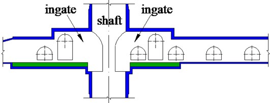
Vertical shaft ingate in coal mine refers to the connection parts of pit shaft and shaft bottom roadway, including upper and lower shaft of ingate and both sides of the connection of big chamber, and some necessary relevant chambers in its vicinity are arranged, including waiting room, control room, distribution room, hydraulic pump room, etc, as shown in Fig. 1. Due to the fact that deep vertical shaft ingate is located at the throat site of mine, possessing the characteristics of large section, complex structure and intensive layout of surrounding roadway chambers [1, 2], thus ingate surrounding rock bears the most serious effect by vibration load produced in the process of excavation and blasting under entire construction of mine roadway and chamber, making deep vertical shaft ingate almost without exception needs secondary repair, however, the repair work will become a new disturbance source, which is very unfavorable for control of surrounding rock stability. Therefore, control technology of surrounding rock stability in deep vertical shaft ingate has become a major technical problem urgently to be solved in mine construction.
At present, the research on stability of surrounding rock in deep vertical shaft ingate has made many achievements, such as Sun Kai et al provided supporting scheme of combination support with secondary support as to No. 1 auxiliary vertical kilometer deep ingate in Cixi Coal Mine, its situations are high geostress, soft surrounding rock and poor stability which has obtained good supporting effects[3]. Xu Tao et al has carried on surrounding rock deformation monitoring and provided reinforcement design of supporting structure based on the monitoring results of ingate, it has avoided vertical kilometer deep ingate is in disturbance under blasting construction for many times, which may cause the instability of ingate surrounding rock [4]. Xu Yu et al. developed the compound repair project of cable anchor support + U-steel yieldable support + reinforced concrete walling secondary support + full section bolt-grouting reinforcement + floor anchor cable bundle, according to the geological condition and damage of ingate which is buried in high stress, expansile and jointed compound soft rock [5]. Dong Jiantao et al. analyzed the failed section of the ingate in shaft of Qujiang Mine with deep location and soft rock, determined to adopt the comprehensive repair project of the deep hole grouting + pre-stressed anchor + bolt and grouting + channel steel ring and concrete reversed arch [6]. In addition, British man altounyan developed the testing device independently, monitored the stress-strain and temperature of ingate through the frozen Bunter Sandstone, and obtained important design parameters [7]. John et al. has studied the condition of serious ingate floor heave on the initial stage of excavation, pointed out that with the method of the undercover cannot solve the problem fundamentally and need for secondary support [8]. With the above introduction, at present the research on controlling stability of surrounding rock in deep vertical shaft ingate is mainly aimed at support technology of the specific complex structure of ingate, and focuses on repairing techniques and optimization after the failure of supporting structure, instead of studying on ingate surrounding chamber group and ingate surrounding rock damage under blasting vibration. And in the field measurement aspect of influence on rock mass damage under blasting excavation, Dong Qian monitored the damage of adjacent surrounding rock chamber in Xiluodu underground diversion cavern group which is in the process of blasting vibration [9]. Lui Minggui et al. monitored the damage and displacement deformation of surrounding rock in Damaoshan tunnel group with small clear distance in the process of blasting construction [10]. Nick monitored the damage of adjacent roadway surrounding rock affected by vibration shock wave in the process of excavation and blasting in coal mine roadway [11]. It has not yet found the instance of damage monitoring on ingate rock mass under blasting vibration, the reason is mainly due to the special geographical location of ingate, which has important contact channels, it is a must for underground personnel, materials and large excavation equipment transported to the working face through ingate, this brought great inconvenience to the field monitoring, at the same time the ingate section is usually in 10-15 meters height, which limited the spendable tools in coal mine, this brought huge inconvenience to the test point arrangement. It can be sure that the blasting damage degree of ingate rock mass is certainly different from that chamber and tunnel, the reason is large cross section of ingate and connection with the shaft directly, which stress concentration is more prone to occur, resulting in instability and failure of structures. It is necessary to monitor the damage of ingate rock mass under blasting vibration.
Fig. 1Deep vertical shaft ingate and distribution of surrounding chambers in coal mine
It is lack of field measurement data of ingate surrounding rock damage in the process of blasting vibration that causes incomplete understanding of ingate surrounding rock damage under excavation and blasting, ignoring the influence of blasting vibration in terms of the surrounding rock control, at the same time there is no serious researches on the reasonable spacing of adjacent chamber group. The author believes that above two aspects are the reasons why large deformation and more likely instability of structure happened in ingate surrounding rock. Therefore, this paper analyses from the above two aspects, monitoring the surrounding rock damage of both sides of roadway connected with ingate under excavation and blasting for the first time, which determine the scope of the blasting damage, several new measures on weakening blasting vibration effect combined with the engineering field are given, and breaking the traditional layout of small scale and concentration in ingate surrounding chamber group, design concept of decentralized arrangements and optimization of construction sequence are provided for the first time. Finally, the research achievements of this paper has been successfully applied to practical engineering, the monitoring results of ingate surrounding rock deformation shows that optimization design of the ingate can maintain good integrity, making no difference in the downhole safety construction, having provided a guarantee for safety production in coal mine.
2. Blasting vibration effects on crack expansion in ingate surrounding rock
The excavation of chamber group connected with deep shaft is a gradual process, which is generally used the method of drilling and blasting construction [12]. Therefore, the surrounding rock within the inherent crack length will further increase, produce more branches and form an annular fracture network under blasting vibration load in excavation process of mine roadway and chamber, which cause a crush of the rock mass [13], ingate in its construction process, due to the blasting face adjoining to the reinforced concrete walling, the surrounding rock in mine roadway which has already formed, and grouting shaft and reinforced concrete walling suffer great vibration load under blasting shock wave, which is extremely easy to be instable and damaged, hence it is necessary to take theoretical analysis on crack expansion in ingate surrounding rock under blasting vibration load.
The influence of dynamic blasting load of fracture extension of rock mainly embodied the effect on the crack by part tensile stress field produced by blasting stress wave, according to the maximum tensile stress criterion to determine the expansion of the crack length [14]. Away from explosion source in the rock, under the action of horizontal stress and vertical stress, a length of 2 initials micro cracks, and then the crack of normal stress is , as shown in Fig. 2.
Fig. 2Under blasting vibration loading crack of surrounding rock stress diagram
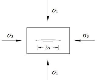
In Fig. 2, is vertical stress of the crack under the action of blasting vibration, MPa; is horizontal stress of the crack under the action of blasting vibration, MPa; is half length of the crack, m.
Due to the explosive stress wave in the process of transmission is diminishing, the radial stress and tangential stress that away from the wave can be calculated as follows:
where is radial stress produced by the rock explosion stress wave, MPa; is tangential tensile stress produced by the rock explosion stress wave, MPa; negative expressed as tensile stress, in this paper calculation shall take its absolute value; is blasthole radius, m; is the distance from the fracture position to the center of the blasthole, m; is the initial impact pressure in the hole-wall, MPa; is lateral pressure coefficient; calculated as follows: , among them is the dynamic Poisson’s ratio of the rock, and , is the static Poisson’s ratio of the rock; is load decaying exponential, .
Under the pressure stress field produced by fissure in blasting stress wave, there will form new tensile stress, at this time, the normal stress on the fissure can be expressed as:
where is normal stress, MPa; is new derivatives of tensile stress, MPa.
According to the fissure extension start-stop condition [15], for I type (open type or tensile) fissure, when stress intensity factor of the crack tip is greater than the fracture toughness of rock crack started to crack, crack extension conversely.
Assume that fissure stability, vibration load changes over time, the fissure conditions similar to the static situation, namely:
where is stress intensity factor of the crack tip, MPa·m1/2; is fracture toughness of rock, MPa·m1/2.
For mode I fissure, consider its cutting-edge maximum destructive effect, the biggest stress component in fissure tip is:
where is fissure tip maximum stress component, MPa; is fissure extension length, m.
When the biggest tensile stress produced by blasting load in the fissure tip is greater than the dynamic tensile strength of the rock, fissure began to extend and expand; when the biggest tensile stress in the fissure tip is less than the dynamic tensile strength of the rock, the fissure start crack-stopping, and then the fissure initiation must satisfy:
where is dynamic tensile strength of rock, MPa.
When considering the initial damage of rock mass, Eq. (4) can be rewritten into:
where is initial damage factor of rock mass.
Substitute Eq. (4) into the above formula, then:
Transform the above formula, then:
Thus, a maximum length of fissure extension is:
where is maximum length of fissure extension, m.
From the above analysis, the maximum length of fissure extension of ingate surrounding rock increases with its distance from explosive source to decreases rapidly, so on the premise of not affecting use function, can appropriately increase spacing distribution of around chambers, in order to reduce the influence of blasting vibration on the rock mass.
3. The damage monitoring on the ingate rock that effect by blasting vibration
Lane excavation blasting process make ingate damage accumulation and instability of rock mass damage, it mainly embodied in two aspects: on the one hand, the vibration of blast shock wave effect makes rock mass mechanics performance degradation, reduce the strength and elastic modulus of rock mass; on the other hand, it is some random distribution for new fissure in rock mass, and further expansion of original fissure and so on, which affect the integrity of the rock mass [16]. The above two aspects can through change of the size and distribution of rock acoustic velocity response. According to the characters of the change of the velocity of sound, identifying the damage of rock blasting and its cumulative growth, establish the relationship between damage of rock mass and the sound velocity decrease rate such as Eq. (10):
where is rock damage under blasting vibration, is sound velocity decrease rate, , is elastic modulus of rock mass before blasting, is equivalent elastic modulus of rock mass after blasting, is acoustic wave velocity of rock mass before blasting, is acoustic wave velocity of rock mass after blasting. Depending on the type rock acoustic test can be obtained by the change of rock mass damage norm provision 10 %, which judge rock mass damage, namely the critical damage threshold 0.19.
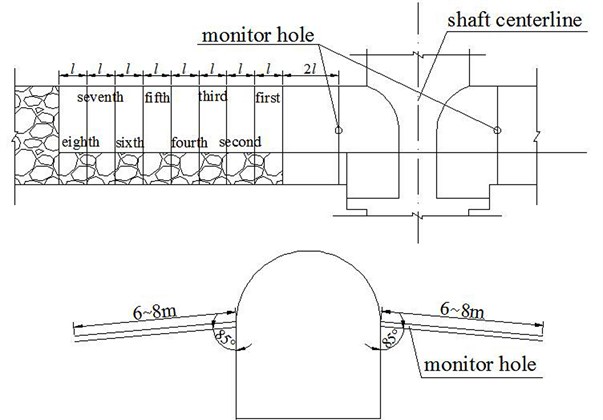
The damage blasting monitoring of ingate rock at –906 m a mine in Huainan mining area, elevation of –884.0~–913.5 m, the main lithology in ingate area are mudstone, siltstone, sandstone. Bench cut method is used for the ingate drivage construction and brush forming, there are many hole on the above bench, large blasting section, disturbance monitoring for the main research object. In the test the wedge shaped cutting was used in the blasting, vertical depth of the cut hole from 2.5 m to 2.6 m, in the middle of the cut hole design two 2.6 m deep vertical holes, in order to increase cutting energy. Other hole depth of 2.3 m, design neighboring hole spacing from 300 mm to 400 mm, controlling other caving hole spacing and row spacing in 550 mm to 700 mm. Construction is used lower power coal mine water-gel explosive, the design adopts two kinds of blast hole diameter and explosive cartridge: cut hole is Φ40 mm diameter hole, with Φ35 mm×200 mm×240 g cartridge. The rest of the hole, such as caving hole, neighboring hole and bottom hole adopt Φ32 mm diameter hole, with Φ27 mm×430 mm×300 g cartridge. Circular hole number is 84, circular explosive consumption is about 55 kg, circulation footage of 2.0-2.2 m, during the field test hole depth and design depth is slightly different, the error is within 5 cm.
Rock mass acoustic test adopt BA - II single-hole sonic tester, as shown in Fig. 3. Monitoring location selection near the ingate wellhead, and specific arrangement as shown in Fig. 4, which l for single blasting excavation footage. Decorate one to each side of the ingate section, decorate a hole that each section on both sides of the same level, monitoring hole drilling depth of 6-8 m, and horizontal tilt is about 5°. Test with water-coupled to prevent hole debris jam blow out cuttings with sweeping hole test before test, then put penetration rod with acoustic emission and receivers in the bottom of the hole, the tail of penetration rod connected to pipe and orifice with a stopper blocked; open the water valve to the hole with water, water overflow as fill, then can measure ultrasonic wave velocity, moving the penetration rod toward the orifice out of 20 cm after fetching data, for the next test, in turn until the hole testing is completed. If water from the rock fissure seepage is serious, we can open water valve to ensure that the borehole in the inland waters – coupled condition.
Fig. 3Ultrasonic tester
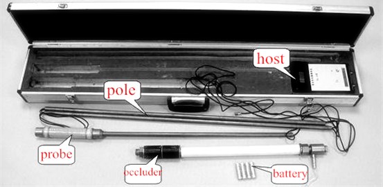
Fig. 4Damage monitoring of blasting vibration on the ingate surrounding rock
Ingate initial damage refers to connect lane tunneling measured less than two tunneling footage of surrounding rock damage after blasting construction. Due to borehole tilt down can’t get near the orifice water filling and water-coupled is poorer, so less than 1 m deep hole range, unable to obtain valid data. Within the scope of 1 m to 6 m depth, test area east and west ingate two section of the sound velocity test data as shown in Fig. 5. Test found that the ingate tunneling blasting damage degree of surrounding rock is large, the blasting influence depth is about 2.4-2.6 m, the ingate surrounding rock mass sound velocity is not completely with depth increases with the increasing, acoustic velocity fell sharply in the depth of blasting effect, may be local breakage or small holes in rock mass.
The acoustic velocity variation of surrounding rock that depth is more than 3 m is small, it shows that affected by disturbance of surrounding rock is small, wave velocity of surrounding rock that the depth is more than 3 m as not damage wave velocity homogeneous wave velocity of surrounding rock, according to the Eq. (10) can obtain the surrounding rock damage within 1-5.8 m after ingate excavation blasting as shown in the Fig. 6, reflects the surrounding rock mass depth that greater than the critical damage threshold is about 2.4 m.
Fig. 5Surrounding rock mass sound velocity curve relationship with depth after excavation blasting
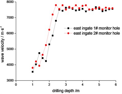
a) East ingate sound velocity curve relationship with depth after blasting rock
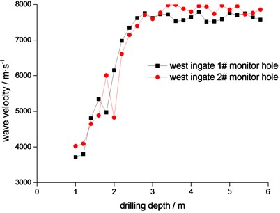
b) West ingate sound velocity curve relationship with depth after blasting rock
Fig. 6Initial damage of ingate in excavating blast
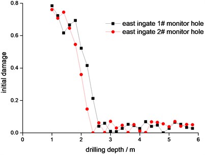
a) East ingate initial damage curve relationship with depth in excavating blast
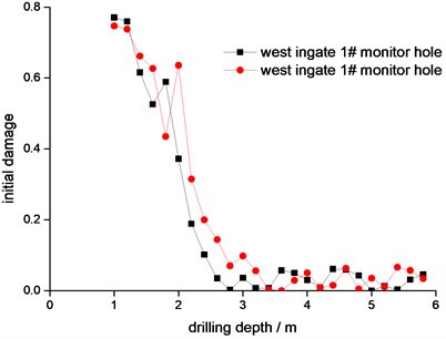
b) West ingate initial damage curve relationship with depth in excavating blast
In order to monitoring the cumulative damage of ingate surrounding rock with many times of blasting vibration, sound velocity testing for the same drilling should conducted respectively after multiple blasting, and hole cleaning processing would be started when the hole blocking appeared in the testing. The testing took 8 times with the excavation of ingate top step, the result varies with multiple blasting in the sound velocity of surrounding rock, as illustrated in Fig. 7.
Acoustic velocity of ingate surrounding rock decreased gradually with the increase of blasting times, which manifested that the effect by blasting in rock mass increases constantly and the integrity in rock mass degraded continually. The decline in sound velocity of surrounding rock by blasting decreased gradually with the distance increasing between testing spot and explosion source, it is accorded with theoretical calculations. It is also can be seen from Fig. 7 that the damage of surrounding rock in each blasting appeared monotonic increasing with the adding of blasting times, and it illustrated that the integrity of surrounding rock deteriorated continuously and the damage aggravated in the effect of blasting. After 8 times blasting, the accumulative damage effect of surrounding rock mass should have obvious non-linear properties, the damage increment both in seventh blasting and eighth blasting are very small. The reason for the foregoing state is that the distance between testing point and explosion source is different, namely rock mass damaged more serious when explosion source is more close to testing point, and also the non-linear properties of growth carve in accumulative damage is the most obvious. Meanwhile, testing carve of all holes are illustrated that the accumulative damage increment in the depth of 2.2 meters to 3.4 meters by blasting is largest, because initial damage is more serious in the shallow surrounding rock which depth is less than 2.2 meters, its damage value is always greater than 0.6. The surrounding rock in 2.2 meters to 3.4 meters is local fracture zone, initial damage is always less than 0.19, the damage accumulative effect is very remarkable in surrounding rock blasting with the vigorous blasting quiver. In consideration of subsequent further excavation in roadway around ingate accordingly created blasting damage accumulation constantly. When damage reached a certain degree, the ingate surrounding rock is in instability failure, therefore, it is very important to control blasting quiver for the reducing of damage in ingate surrounding rock.
Fig. 7Surrounding rock damage of ingate in multiple blasting quiver
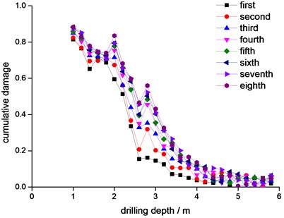
a) East ingate 1# monitor hole
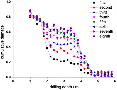
b) East ingate 2# monitor hole
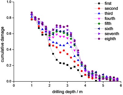
c) West ingate 1# monitor hole
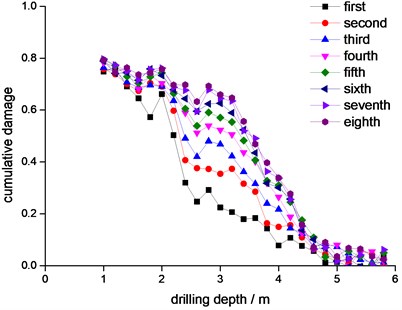
d) West ingate 2# monitor hole
4. The control measures for weakening the surrounding rock damage effect of deep vertical shaft ingate in blasting quiver.
4.1. Charge structure optimization
Columnar decoupling charge is adopted in charge structure, because the decoupling medium in gaps has a buffered action to the detonation wave which produced in explosive blasting. The strength of blasting seismic wave which is generated by decoupling charge is less than coupling charge under the same of priming charge. In addition, sublevel charge is adopted. As shown in Fig. 8, upper and down segments is implemented in the blast hole of cut charge, sublevel charge is separated by a critical length of stemming and priming in outside-in sequence.
According to the mode of cutting as above, the testing is conducted in –790 meters west rail roadway of a coal mine, rock in this roadway is mainly by mudstone and sandy mudstone, and its firmness coefficient 9-10, the depth of blast hole is 2.5-2.8 meters, and the average utilization of blast hole is 90.5 %. By the vibration monitoring, the velocity of blast quiver by using sublevel cut is reduced 15 %-20 % than traditional continuously charge cut [17], and its vibration attenuation effect is obvious.
Fig. 8Straight-shot sublevel cut in hole

4.2. Priming technology in millisecond delay
The millisecond delay electric detonator is used for underground coal mine, its delay time interval between segments is 20 ms and the total delay time is less than 130ms. With the increase of roadway section, detonator segments are not enough in construction or overmuch blast hole in a segment detonation are appeared gradually, which indicated that the in-site requirements are not meet by the existing regulation for delay time [18, 19]. By changing delay time interval between segments and the total delay time remain the same, our group conducting a testing on large section of soft rock roadway, and throwing distance of gangue reduced from 20 m-25 m before test to 10 m-15 m during the test. Moreover, its vibration velocity is distinct less than previous and achieved good results.
4.3. The setting for isolation hole
In order to reducing the disturbance of subsequent construction, isolation measures adopted is an effective technological approach. A row of intensive deep drilling is drilled between two main roadways in the before and after constructions, which insulated and attenuated the vibration shock wave and deformation disturbance by the intensive deep drilling in the subsequent roadway construction, and reduced the effect to surrounding rock stability of roadway which is supported.
4.4. The optimization design for chamber group around ingate
According to past experiences and methods in the design of shallow buried mine, in order to meet the convenience of utilization function and reduce the quantities of roadway excavation, the related caverns around ingate always arranged intensively in the small range of ingate and shaft station, and the common arranged form of chamber group is developed [20-23]. Because the related cavern is excavated after ingate constructing, its construction method, technology, support and arrangement has a certain effect on disturbance. The harmfulness of the “disturbance” for shallow mine is not obvious, therefore, the in-depth research in its regularity is not proceeded. However, for deep vertical shaft, because the small range of intensive arrangement and construction in related caverns and channels, the support structure in two wings of ingate and a certain range in its upper and down suffered the repeated disturbance by subsequent excavation, and the disturbance highlighted in the combined action with high geostress of deep well. With the action of repeated and multiple constructing disturbance, concrete spalling, reinforcement bending and section reducing in different directions are appeared in the reinforced concrete supporting structure of ingate and a certain range in its upper and down. In severe cases, even surrounding rock instability would happen and large deformation and serious broken state would appear in supporting structure. All of these bring a harm for the safety of shaft and ingate, and the safety production of mine is threatened [24-26].
In order to reduce quiver effect to a minimum which produced in the excavation of adjacent caverns and guarantee the stability of roadway surrounding rock and supporting structure, the optimization of position arrangement for related caverns and channels and reasonable distance determination, disturbance reducing is the most effective and practical technical solution which is first proposed. This so-called reasonable distance determination is that the existing methods of intensive arrangement in small range of related caverns is changed, intervals between related caverns is determined reasonable, and impact of the “disturbance” in excavation is reduced to a minimum, thereby, the support structure in two wings of ingate and a certain range in its upper and down is protected from disturbance and damage.
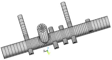
The finite difference methods program FLAC3D is adopted to simulated analysis in the constructing of cavern group, this program solving the governing differential equation of field by Lagrangian method, and the application of mixed element discrete model could simulate rock material better in the process of yield, soften, large deformation and underground engineering construction. The –906 m horizontal cavern group in a mine as the object of research for the model. According to the designing solution of cavern group and considering the range of effect in cavern excavation, thereby, 3D numerical calculation model is established. The width of model (along ingate cavern horizontally) is 60 m, longitudinal length (along ingate cavern vertical) is 100 m and height (along vertical shaft vertical) is 60 m. Hexahedral element is adopted by calculation model to partition, and 75684 elements are generated. Mesh generation of model as shown in Figs. 9-10, this cavern group is made of vertical shaft, ingate, two control rooms, two hydraulic pumping stations, two lounges, two transformer rooms and one train manipulation room [27].
Fig. 9The meshing of model
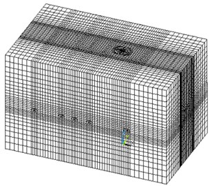
Fig. 10The distribution of ingate and surrounding caverns
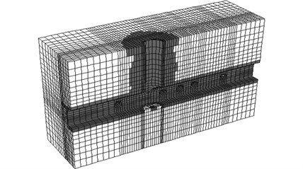
The numerical calculation is carried out by using the original design scheme, the results shown in Fig. 11, around the shaft and each chamber has a certain range of the plastic zone and ingate in the plastic zone at the maximum, which is not conducive to ingate structure safety, so it is necessary to optimization of the original design.
Through numerical simulation and field monitoring results continuously optimized the original design scheme, finally make the following adjustments. Position layout of original shaft, shaft station and main cavern roadway have been optimized, and the distance between main roadways and shaft have increased, such as –906 m horizontal shaft station and main caverns etc. And it avoided to produce stress concentration and stress superposition and increased the rock pillars, reducing influence on shaft, shaft station and the main cavern disturbance in construction period, to ensure the stability of the surrounding rock and the construction safety. Specific optimization scheme is as follows: the distance between –906 m horizontal empty shaft station and heavy station increased to 50 m by 40 m of original design; the distance between –906 m central substation, central pumping station and shaft increased to 45 m by 35 m of original design; the distance between –906 m waiting room, roadway and shaft increased to 22 m by 12 m of original design; the distance between –906 m roadway of central substation and shaft increased to 48 m by 32 m of original design; the distance between –906 m roadway of central pumping station and shaft increased to 90 m by 45 m of original design; the distance between –906 m central substation, central pumping station and internal warehouse increased to 100 m by 40 m of original design. And optimize the design scheme of original support of the horizontal chamber group, namely, the original anchor mesh spray initial support and inverted arch + cast in place reinforced concrete forms of secondary support is adjusted to anchor boltmesh initial support and cast in place reinforced concrete forms of secondary support. The anti-bottom arch is cancelled, and the flat bottom structure is adopted, which reduces the construction difficulty. At the same time, according to the following method to select the optimal chamber group construction sequence scheme, reducing crushing damage of surrounding rock caused by excavation blasting.
Fig. 11Plastic zone of chamber group surrounding rock
Based on the above optimized design of the chambers, the entire cavern group is divided into A, B, C, D, E, F the six parts totally, which corresponding to the vertical shaft (A), ingate (B) and cavern respectively. Ingate is divided into two parts: east ingate (B1) and west ingate (B2), cavern group D is divided into north cavern (D1) and south cavern group (D2), as shown in Fig. 12.
Fig. 12The overall division of cavern groups
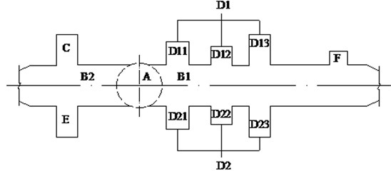
Consideration on various factors such as the actual construction conditions and the construction cost of slag transport system and the construction layout of machinery. When using the enumeration method to arrange the construction plan [28], the assumptions should be defined for: (1) A is the first step of excavation; (2) C step must behind B2 step of excavation; (3) D1, D2, must behind B1 on excavation; (4) Three same side cavern included in D1 and D2 must excavated continuously; (5) D and E should work after C; (6) F is a train control room, which apart from the left side of the east waiting room about 16.7 m, and the section of train control room is 4 m. Because of it, the influence on stability of surrounding rock of the overall cavern group, which is negligible to identified as a final step of excavation. Accordingly, a total of 432 excavation sequence combination plan of cavern group adopted by enumeration method, and the optimization problem is to find the optimal solution in the 432 kinds of scheme, and it is impossible and unnecessary for so many scheme numerical simulation compared one by one, in fact, so according to the theory of dynamic programming, choose the limited calculation from these solutions and compared with variety solutions, as shown in Table 1, and using the volume of damaged zone of surrounding rock of cavern group (unit: m3), as the revenue function (optimization index), selecting the optimal construction scheme finally.
Table 1The dynamic optimization programming of construction sequence of cavern group
Stage | Scheme | Volume of damaged zone/m3 | Optimal scheme of stage | Stage | Scheme | Volume of damaged zone/m3 | Optimal scheme of stage |
1 | A-B1-B2-C | 1439 | 3 | A-B2-C-B1-E-D11 | 2222 | ||
A-B2-B1-C | 1278 | A-B2-C-B1-E-D12 | 1974 | ||||
A-B2-C-B1 | 886 | * | A-B2-C-B1-E-D13 | 2060 | |||
2 | A-B2-C-B1-D11 | 2098 | A-B2-C-B1-E-D21 | 2099 | |||
A-B2-C-B1-D12 | 1783 | A-B2-C-B1-E-D22 | 1955 | * | |||
A-B2-C-B1-D13 | 1979 | A-B2-C-B1-E-D23 | 2095 | ||||
A-B2-C-B1-D21 | 2035 | A-B2-C-B1-E-D13 | 2060 | ||||
A-B2-C-B1-D22 | 1781 | A-B2-C-B1-E-D21 | 2099 | ||||
A-B2-C-B1-D23 | 1793 | 4 | A-B2-C-B1-E-D22-D21 | 1997 | * | ||
A-B2-C-B1-E | 907 | * | A-B2-C-B1-E-D22-D23 | 2654 | |||
5 | A-B2-C-B1-E-D22-D21-D23-D11 | 2645 | * | 6 | A-B2-C-B1-E-D22-D21-D23-D11-D12 | 3205 | |
A-B2-C-B1-E-D22-D21-D23-D12 | 2732 | A-B2-C-B1-E-D22-D21-D23-D11-D13 | 2939 | * | |||
A-B2-C-B1-E-D22-D21-D23-D13 | 3067 | Optimal construction scheme of cavern group: A-B2-C-B1-E-D22-D21-D23-D11-D13-D12-F | |||||
Specific analysis process: first of all, numerical simulation should be done for the scheme construction order of A-B1-B2-C, A-B2-B1-C, A-B2-C-B1 three cavern groups, and find out the smallest one option of profit function which is damaged zone of surrounding rock volume value, abandoning the other two schemes, and it is concluded that the calculation construction of optimal solution under the premise to be continued at this stage, so on to find out the optimal solution. Specific optimization process of the construction sequence for cavern group is shown in Table 1, it shows that the calculation workload reduced greatly through reduce the numerical simulation of the dynamic programming principle from 432 times to 25 times. Finally, optimal construction scheme for cavern group is A-B2-C-B1-E-D22-D21-D23-D11-D13-D12-F.
5. Evaluation of project effect
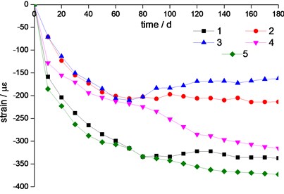
The research results above could be applied to the ingate and the surrounding cavern group of the mine project eventually, by long time monitoring of lining deformation of ingate of the cavern excavation under disturbance, the results showed that the dispersion of cavern group of design form should be used, and using the blasting vibration effect of control method for ingate lining deformation which obtained a very good control, ensured its safe use under the original support form. The ingate deformation monitoring as shown in Figs. 13-15. The value of steel reinforced stress was 76.8 MPa, and its size is less than 42 percent of design value; a maximum of micro strain of concrete is 369.3 με, and the design value is 2000 με, a maximum value of micro strain is only 18.5 percent of design, and strain – time curve go flattens.
Fig. 13The component schematic for monitoring fracture section of ingate
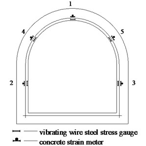
Fig. 14The changing curve of reinforcement stresses along with the time of monitor
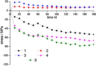
Fig. 15The changing curve of strain of concrete along with the time of monitor
6. Conclusion
1) For the first time, the damage monitoring for blasting vibration impact of surrounding rock of ingate under lane excavation blasting process, determined the scope of the blasting damage of rock mass. The largest cumulative incremental of blasting damage for surrounding rock changes within the scope from 2.2 m to 3.4 m, and its damage value is greater than 0.6. And it is the local fracture zone of surrounding rock within the scope from 2.2 m to 3.4 m, which initial damage is less than 0.19. Damage cumulative effect is remarkable under the intense blasting vibration of surrounding rock blasting.
2) For the first time, ingate and cavern group have considered as a whole, and reasonable arrangement spacing was determined by the numerical simulation of cavern group of ingate, reducing the blasting vibration of ingate damage of surrounding rock with the method of dispersion effectively, and optimized the construction sequence of cavern group. The monitoring of field engineering shows that the arch walling of ingate could keep good integrity under the original support conditions by adopting these controlling measures of ingate under blasting vibration given in this paper.
References
-
He M. C., Xie H. P., Peng S. P., et al. Study on rock mechanics in deep mining engineering. Chinese Journal of Rock Mechanics and Engineering, Vol. 24, Issue 16, 2005, p. 2803-2812.
-
Liu Y. S., Zhao J. Z., Yang J. E., et al. Restoration in practice and theory of 1000 m deep shaft ingate and shaft wall. Mine Construction Technology, Vol. 26, Issue 3, 2005, p. 1-6.
-
Sun K., Lin D. G., Zhang S. L. Study on ingate support technology of 1000 m. Mine Construction Technology, Vol. 36, Issue 1, 2015, p. 43-46.
-
Xu T., Rong C. X., Li S. L. Auxiliary shaft ingate rock deformation monitoring and reinforcement design for support structure. Coal Technology, Vol. 33, Issue 9, 2014, p. 121-123.
-
Xu Y., Chen X. M., Jiao H. Z. Technology of compound soft rock supporting for deep shaft ingate in Zhaogu No. 2 coal mine. Metal Mine, Vol. 430, Issue 4, 2014, p. 32-35.
-
Dong J. T., He G. L., Zhang G. Study on repair and control technology for failed ingate in deep soft rock of mine shaft. Coal Engineering, Vol. 36, Issue 2, 2009, p. 25-27.
-
Altounyan P. F. R. Measurement of stresses, strain and temperature in concrete in shafts and insets. Developments in Geotechnical Engineering, Vol. 32, 1981, p. 154-159.
-
John K. B., Philip D. S., Nevil T. Deformation of a deep shaft inset in coal measures rocks during and after construction Developments in Geotechnical Engineering, Vol. 32, 1981, p. 167-173.
-
Dong Q. Influence Research of Underground Caverns Blasting Excavation on Excavation Damage Zone of Adjacent Cavern. Wuhan University of Technology, WuHan.
-
Liu M. G., Zhang G. H., Liu S. B., et al. Research on accumulative damage effect of interlaid rock in Damaoshan tunnel group with small clear small clear distance. Chinese Journal of Rock Mechanics and Engineering, Vol. 28, Issue 7, 2009, p. 1363-1369.
-
Nick W. S. Analysis of blasting damage in adjacent mining excavations. Journal of Rock Mechanics and Geotechnical Engineering, Vol. 7, 2015, p. 282-290.
-
Nasir A., Steven S., Sildomar T. M., et al. Adaptive sampling applied to blast-hole drilling in surface mining. International Journal of Rock Mechanics and Mining Sciences, Vol. 75, 2015, p. 244-255.
-
Yang J. H., Lu W. B., Zhao Z. G., et al. Safety distance for secondary shotcrete subjected to blasting vibration in Jinping-II deep-buried tunnels. Tunnelling and Underground Space Technology, Vol. 43, 2014, p. 123-132.
-
Mirsayar M. M. Mixed mode fracture analysis using extended maximum tangential strain criterion. Materials and Design, Vol. 86, 2015, p. 941-947.
-
Cheng H., Cai H. B., Rong C. X., et al. Rock stability analysis and support countermeasure of chamber group connected with deep shaft. Journal of China Coal Society, Vol. 36, Issue 2, 2011, p. 261-266.
-
Hu H. T., Lin W. P., Tu F. T. Failure analysis of fiber-reinforced composite laminates subjected to biaxial loads. Composites Part B-engineering, Vol. 83, 2015, p. 153-165.
-
Zheng Z. T., Xu Y., Dong J. H., et al. Hard rock deep hole cutting blasting technology in vertical shaft freezing bedrock section construction. Journal of Vibroengineering, Vol. 17, Issue 3, 2015, p. 1105-1119.
-
Majid R., Ayatollahi S. M., Mohd Y. Y. Mixed mode fatigue crack initiation and growth in a CT specimen repaired by stop hole technique. Engineering Fracture Mechanics, Vol. 145, 2015, p. 115-127.
-
Blair D. P. The free surface influence on blast vibration. International Journal of Rock Mechanics and Mining Sciences, Vol. 77, 2015, p. 182-191.
-
Han B., Ma Q. Y. Research on testing and controlling techniques of millisecond delay blasting vibration in coal mine rock roadway. Journal of China Coal Society, Vol. 38, Issue 2, 2013, p. 209-214.
-
Liu Z., Zhu C. Q., Xie D. H., et al. Optimized design and practice of blasting parameters for hard rock roadway with small cross-section. Journal of Mining and Safety Engineering, Vol. 24, Issue 1, 2007, p. 55-61.
-
Liu Y. X., Shao C. Y., Yang R. B. Construction technology for large span chamber group in 1000 m deep rocks of Tangkou Mine. Coal Science and Technology, Vol. 34, Issue 12, 2006, p. 35-37.
-
Jiang Y. S. Analysis on destruction of air shaft ingate in Liuzhuang Coal Mine. Mining Research and Development, Vol. 28, Issue 4, 2008, p. 19-21.
-
Xiao T. Q., Li H. M., Yang J. l., et al. Deformation and failure mechanism of surrounding rock in chamber with super large section and its control. Journal of China Coal Society, Vol. 39, Issue 4, 2014, p. 631-636.
-
Wang T. J., Su L. J., Jia H. B. Study on construction technology of large section central pump chamber. Mining Technology, Vol. 11, Issue 5, 2011, p. 14-16.
-
Yao Z. S., Cheng H., Gao Y. L., et al. Ingate support structure and application in deep mine shaft with complicated geological conditions. Coal Science and Technology, Vol. 37, Issue 1, 2009, p. 69-71.
-
Cai H. B., Cheng H., Rong C. X., et al. Rock stability analysis and supporting structure optimization of deep shaft ingate under complex conditions. Journal of Mining and Safety Engineering, Vol. 32, Issue 2, 2015, p. 298-304.
-
Liu Y. S., Zhao J. Z., Yang J. E., et al. Restoration in practice and theory of 1000 m deep shaft ingate and shaft wall. Mine Construction Technology, Vol. 26, Issue 3, 2005, p. 1-6.
Cited by
About this article

This research was founded by the National Natural Science Foundation of China (No. 50874002) the Specialized Research Fund for the Doctoral Program of Higher Education (No. 20133415110004) and Anhui Province Science and Technology Project (KJ2010B318, KJ2012A094).
