Abstract
An electromagnetic launcher (EML) is a device used to propel and accelerate a projectile by converting electrical energy into kinetic energy. A coil gun, which is a type of EML, can propel a projectile without any mechanical friction so that there is no theoretical limit to the velocity. A multi-stage system is a way to raise the effectiveness of the coil gun. It accelerates the projectile by controlling the relations between each stage of the solenoid and projectile. Since a multi-stage system controls the time needed to apply electric current to the coil depending on the position of the projectile, the switching time is extremely important. We performed a finite element analysis using MAXWELL to determine the extent to which the velocity of a multi-stage coil gun improved compared to a single-stage coil gun. In addition, we verified the two-stage performance through timing control by designing and producing a two-stage coil gun based on our research results for a single-stage coil gun. The velocity was increased by 34 % compared to the single-stage coil gun, and the error compared to the analysis result was 16.4 %.
1. Introduction
An electromagnetic launcher (EML) propels a projectile by converting electrical energy into kinetic energy. Thus, it has a significant advantage with respect to storage and maintenance as it is eco-friendly and stable. Extensive research and development on EMLs is underway worldwide. It is possible to use an EML to launch a small satellite into space using electromagnetic force, and to reorganize the development market for large-size satellites into a development market for small-size satellites.
One way to increase the efficiency of a coil gun is to accelerate a projectile by operating several coils sequentially. In this study, we made a prototype for coil-gun system and verified its performance based on the design of a two-stage coil with higher efficiency than a single-stage coil gun based on this method.
Fig. 1Principle of the coil gun
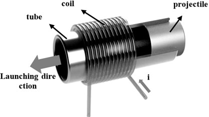
A coil gun propels a projectile using the electromagnetic force generated by Fleming’s right hand law when applying the current to the coil in solenoid form. The coil gun is propelled by force that is acting in all directions on the solenoid by passing through the inside of the cylindrical coil. Fig. 1 shows the principle of the coil gun.
The force acting on the circumference of the projectile by the solenoid is separated into a component in the direction of the circumference and a component in the direction of the axis by the solenoid. Out of these, the projectile is propelled by the force in the direction of the axis. In addition, the force in the direction of the circumference is balanced with the pivot point when the horizontal axis of the projectile matches the horizontal axis of the flyway tube so that the projectile can be propelled from the flyway tube without any mechanical friction. Therefore, there is no theoretical limit to the velocity.
Since a coil gun is largely influenced by the velocity depending on the interval and operation time, it is required to determine the optimal speed by controlling the operation time of each coil. The time needed to apply and block the electric current and the operation time of each coil was determined by conducting finite element analysis using the commercial electromagnetic analysis software program MAXWELL (ver. 16, ANSOFT, USA).
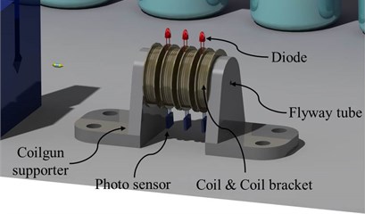
To measure the velocity of the projectile, we produced a prototype of the coil gun system. The coil gun prototype is comprised of a power supply, solenoid coil, guide tube, coil gun support fixture, projectile, and velocity measurement infrared light sensor device. If the projectile is launched along the guide tube after applying the electric current to each coil, the final velocity of the projectile will be measured using the velocity measurement infrared light sensor device installed at the end of the tube.
2. Design of the coil gun
2.1. Coil gun
2.1.1. Structure of coil gun
The whole EML is divided into a coil gun system and electric circuits. As shown in Fig. 2, the coil gun is comprised of a coil, fly tube, coil bracket, and projectile. The materials for each part are listed in Table 1.
Fig. 2Component of the coil gun
The eddy current can be generated in the projectile during the process of propelling the projectile based on the magnetic force produced by applying current to the coil. Thus, we blocked the eddy current by selecting a non-magnetic conductor for the flyway tube material. The coil bracket is included for convenience in the process of coil winding and is made of acrylic material. The projectile is largely composed of magnetic material parts and non-magnetic material parts. Since it is propelled in proportion to the magnetic flux density, the magnetic material gains more momentum as its relative permeability increases. Therefore, the magnetic material of the projectile should be ferromagnetic, and we selected Permalloy 78 nickel alloy. The diameter of a commonly used bullet in a real weapon is about 5.56 mm excluding the cartridge case. Thus, the diameter of the projectile was set to be 6 mm with a length of 23 mm. The projectile is less influenced by gravity as the air gap becomes smaller as it passes through the inside of the flyway tube. Thus, the diameter was set to 0.6 mm with a tube thickness of 0.4 mm. The internal diameter of the solenoid winding in the flyway tube is 7.2 mm.
Table 1Structure and materials of coil gun
Part | Material |
Coil | Enamel-coated copper |
Flyway tube | Aluminum |
Coil bracket | Acrylic |
Projectile | Permalloy 78 |
2.1.2. Design of solenoid
The maximum value and rise time of the electric current flowing over the solenoid is set depending on the design of the solenoid. The design variables of the solenoid were selected as the number of turns in the direction of the axis, and the number of turns in the direction of the radius of the solenoid. The diameter of the coil wire of the solenoid was set to 2 mm. This coil can send about 5200 A of current for 5 msec. If the electric current is applied less than insoluble 5000 A in the coil, the number of turns for the maximum magnetic flux density (B) was designed. Table 2 shows the specifications of the designed solenoid. Table 3 shows the electrical properties of the designed solenoid.
Table 2Solenoid design
Wire diameter | 2 mm |
No. of turns in axis direction | 11 turns |
No. of turns in radius direction | 9 turns |
Internal radius | 3.6 mm |
Table 3Electrical properties
Input voltage | 200 V |
Coil inductance | 0.0946 mH |
Resistance of RLC circuit | 0.0108 Ohms |
Capacitance | 0.1F |
2.1.3. FEM simulation
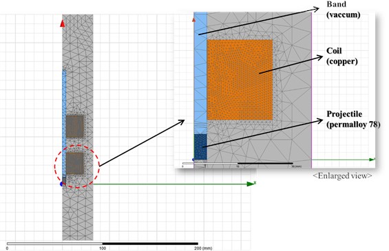
To analyze the changes in the electrical output as the projectile moves in the coil gun, a finite element analysis was conducted using the commercial electromagnetic analysis software MAXWELL. Fig. 3 shows FE model of coils and projectile. Total number of mesh elements is 6338. Fig. 3 shows the input external circuit in MAXWELL to apply electrical properties of the solenoid coil designed in Section 2.1.1. Fig. 5 indicates the output values according to the launch of the projectile.
Fig. 3Mesh plot of FE model
As shown in Fig. 5, there is an area where the electric current is reduced at the middle point of the solenoid coil and at the point with the highest projectile velocity. This is because the magnetic flux from the solenoid coil changes with the entry of the projectile (this is called “back-emf”). Therefore, as the magnetic force has a negative value at this point, it is necessary to block the application of the electric current and voltage at this point. It is very difficult to block the electric current and voltage within a short period of time. Therefore, we applied a timing switch control that blocks the current and voltage at 1.8 msec, depending on the results of the FEA.
Fig. 4External circuit of coil gun in MAXWELL
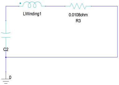
Fig. 5a) Input winding current, b) electromagnetic force, c) moving speed of projectile
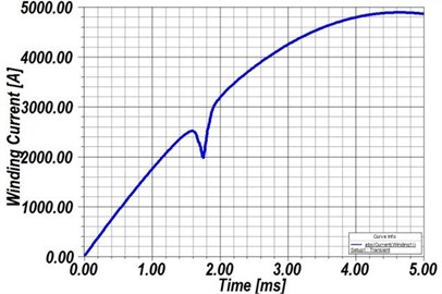
a)
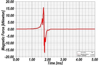
b)
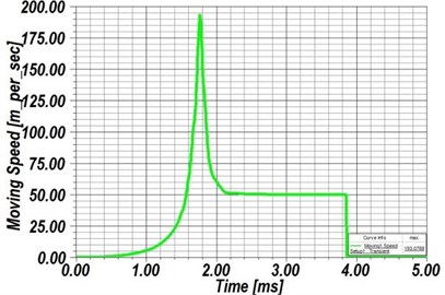
c)
2.2. Design of multi-stage coil gun
2.2.1. Structure of multi-stage coil gun
As a way to improve the efficiency of the coil gun, the use of a multi-stage system accelerates the projectile by controlling the relations between each stage of the solenoid and the projectile. Since the location of the projectile controls the application time of the electric current to the coil, the switching time is very important.
The voltage of two stages is sequentially applied to each coil using the charging and discharging circuits shown in Fig. 6. Applying the voltage is a way to control the operation time depending on the results of the single-stage coil gun test. We now describe the structure of the two-stage coil gun.
Fig. 6Characteristic of electrical circuit
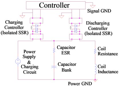
Fig. 7Circuit for two-stage coil gun
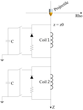
2.2.2. Electric circuit
It is required to control the charging and discharging timing to activate the coil gun. The voltage is charged by connecting the power supply and the capacitor through the charging Solid State Relay (SSR) when charging. In addition, when discharging, the voltage is discharged in the coil by connecting the capacitor and the coil using the discharging SSR as it controls the charging SSR. The on/off switch is controlled through the output of the processor after calculating the charging and discharging time with a microprocessor or digital signal processor (DSP), as shown in Fig. 6.
The appropriate circuit for the two-stage coil gun is shown in Fig. 7. Also, the governing equations of motion can be expressed as following Eq. (1):
where : inductance of the coil, : capacitance of the capacitor, : series resistance of the coil and equivalent resistance of the capacitor.
3. Construction and experiment
The muzzle velocity of the projectile was used as a measurement index. The two power supplies are shown in Fig. 7. The power supplies are touched to each coil. Fig. 8 shows the flow chart of the experiment method. If the switch of the first fully-charged power supply is turned on, the voltage is applied to the first coil and blocked within 2 msec. Depending on the time saved in the timer located between each power supply, the switch of the next coil turns on. When the launched projectile passes through an infrared light sensor device, the display device indicates the velocity, and the launch of the projectile will be blocked by the catcher.
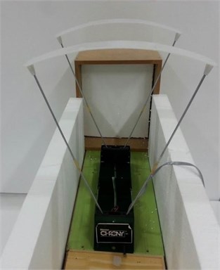
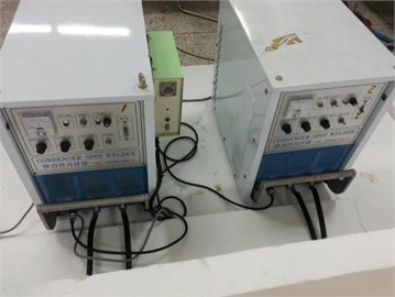
To measure the velocity of the projectile, a prototype of the coil gun system was built as shown in Fig. 9. The prototype is comprised of a solenoid coil, guide tube, coil gun support fixture, and projectile, as shown in Fig. 10(a). An infrared light sensor device and display device to measure the velocity of the projectile are shown in Fig. 10(b). The operating principle is to mark the muzzle velocity of the projectile on the display device, depending on the input/output calculation, where infrared light is reflected on a reflecting board located at the top of the infrared light sensor as the projectile sequentially passes two infrared light sensors located at regular intervals. In addition, we installed the catcher behind the velocity device to reduce the risk of a rebound of the projectile. Fig. 10(c) shows the power supply used to apply current to each coil.
Fig. 8Flow chart of the experiment
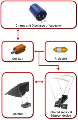
Fig. 9Configuration of experimental system for testing
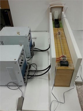
Fig. 10a) Two-stage coil gun system, b) infrared light sensors, c) power supplies
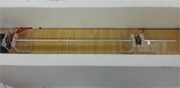
a)
b)
c)
As shown in Table 4, the result of experimental test to measure the velocity of the projectile in the two-stage coil gun system is 54.84 m/s. The error was 16.4 % between experimentally determined velocities of 54.84 m/s and 65.6 m/s based on the electromagnetic analysis results using MAXWELL. Also, the result of numerical simulations is 60.9 m/s. So, the error of the experimental results compared with the numerical results of the two-stage coil gun system is 10.0 %.
Table 4Comparison of results
Result type | Velocity |
Numerical analysis | 60.9 m/s |
Electromagnetic software analysis | 65.6 m/s |
Experimental measurement | 54.84 m/s |
4. Conclusion
We propose a design for a multi-stage coil gun system with a higher velocity than single stage coil gun. To elevate the efficiency of an optimally designed single-stage coil gun system, a multi-stage coil gun system was designed. Since the velocity is proportional to the number of solenoids in the multi-coil gun system, it is hard to control the muzzle velocity of coil gun. Therefore, we used the two-stage approach. The first solenoid coil used the optimally-designed model of the single-stage coil gun system, and the second solenoid coil uses the velocity of the single-stage coil gun system as its initial velocity.
We built and tested a prototype of the proposed two-stage coil gun system. The velocity of the projectile of the two-stage coil gun system was measured to be 54.8 m/s. The error compared with the analysis results of the two-stage coil gun system is 16.4 %. Also, the result of numerical simulations is 60.9 m/s. So, the error of the experimental results compared with the numerical results of the two-stage coil gun system is 10.0 %. This high error rate occurred due to the changes in the magnetic field according to the air resistance, gravity, and thermal energy of the coil. We expect to conduct additional studies in order to improve the energy efficiency and reduce the error of the coil gun system.
References
-
Han J. M., et al. Research of the Driving Characteristic in the Electromagnetic Launcher by Switching Circuit. Thesis, Pusan National University, Korea, 2006.
-
Joo S. J., et al. Development of the small electro -magnetic launcher using solenoid coil. Thesis, Pusan National University, Korea, 2006.
-
Dennison Eric On-Axis Field of a Finite, Straight, Thin Shell Solenoid. Thesis, 2004.
-
McNab Ian R. Launch to space with an electromagnetic railgun. IEEE Transactions on Magnetics, Vol. 39, Issue 1, 2003, p. 295-304.
-
Fair H. D. Advances in electromagnetic launch science and technology and its applications. IEEE Transactions on Magnetics, Vol. 45, Issue 1, 2009.
-
De-man Wang, et al. The magnetic levitation of the projectile in coil guns. IEEE Transactions on Magnetics, Vol. 33, Issue 1, 1997, p. 195-200.
-
Becherini Giancarlo, Tellini Bernardo Helicoidal electromagnetic field for coilgun armature stabilization. IEEE Transactions on Magnetics, Vol. 39, Issue 1, 2003, p. 108-111.
-
Becherini Giancarlo Gyroscopic stabilization of launch package in induction type coil gun. IEEE Transactions on Magnetics, Vol. 37, Issue 1, 2001, p. 116-122.
-
Ki-Bong Kim, et al. In-bore projectile dynamics in the Linear Induction Launcher (LIL). Part 1: oscillations. IEEE Transactions on Magnetics, Vol. 31, Issue 1, 1995, p. 484-488.
-
Xu Lizhong, Geng Yanbo Forces of rails for electromagnetic railguns. Applied Mathematical Modeling, Vol. 36, Issue 4, 2012, p. 1465-1476.
Cited by
About this article

