Abstract
The article describes a three-dimensional simulation of the stationary motion of the gas and condensed phase particles of varying severity in a curvilinear orthogonal coordinate system of channels of gas pipelines. A numerical method for solving the equations that describe the motion of the particles, based on obtaining difference schemes and the use of a two-level iterative process. Built a multi-dimensional mathematical model of the steady flow of viscous gas hydrate particles in equilibrium axisymmetric taking into account transport and energy dissipation. Numerical calculations of the velocity field and the dispersed gas phase trajectory of mass flow of particles deposited on the walls of various sizes in a wet gas flow in a curved pipe.
1. Development of a model of hydrate formation in the flow of raw natural gas in the pipes
On gas and gas condensate fields have been widely used air-cooling. They can be installed after the installation of complex preparation of gas booster station and at other sites.
Blocks air coolers used on gas fields consist of 10-16 units. Each unit has three longitudinal sections of heat exchangers with six rows of horizontal finned tubes. In each row of thirty (twenty-nine) tubes arranged in staggered rows. The flow of cold air from the bottom up through the six series created by two fans placed on a foundation under the tubular section.
Apparatuses for the air cooling operation without hydrate satisfactorily cooled dehydrated natural gas and crude gas at positive ambient temperatures (in the absence of hydrate formation). However, in winter conditions during the cooling of the crude gas after the first stage of the gas booster station receive a number of problems. The bottom row of tubes, as a result of local supercooling gas, there are conditions for the formation of hydrates; on the inner wall of heat exchange tubes formed hydrates, ice, and the individual tubes are destroyed.
To prevent the formation of hydrates while cooling the crude gas in the pipes of air-cooling in practice is necessary to maintain a sufficiently high average gas temperature at the outlet of the apparatus, sometimes up to 18-20 °C, thereby limiting not only the potential of air cooling, but and reducing the quality of the gas being prepared for transport. A particularly acute problem of the quality of training in terms of gas dew point of moisture in a falling reservoir pressure.
The main purpose of air coolers, cooling the crude gas, have a minimum temperature of the gas supplied to the drying in preparing him to further transport. This temperature must not be lower than the temperature of hydrate formation inside the raw gas-cooled heat exchanger tubes most in stationary cooling mode and can be lower than the temperature of hydrate formation at unsteady cooling, when applying pre-drying and the hydrate formation inhibitor supply tube in the lower rows.
A necessary condition for the formation of crystalline hydrates is the presence of moisture in the gas is condensed. The moisture content of the gas is the ratio of mass amount of moisture contained in the wet gas to the mass amount of dry gas. In case of exceeding the dew point temperature of the gas pipeline in the form of gas conditions for the formation of crystalline hydrates. During transport in cold weather conditions for hydrate formation primarily appear on the tube wall, where it is condensed particle deposition. Therefore, it is advisable to consider the multi-dimensional structure of the flow of raw gas, affects the process of hydrate deposits on the walls.
A mathematical model based on the stationary equations of viscous flow recorded in axisymmetric [1]:
where – density of the gas; – pressure; , – velocity components on the axis , ; – coefficient of dynamic viscosity; – gas temperature; , – moisture content of hydrates in the flow; , , – Prandtl and Schmidt numbers; – gas constant of a mixture of combustion products. The density is determined from the equation of state .
The system of equations of motion is considered in conjunction with the transport equations of the kinetic energy and the dissipation rate . The viscosity is determined by the sum of , where , – coefficients of molecular and turbulent viscosity, , , , – empirical coefficients, .
Mass transfer speed of water in the hydrates and the rate of formation of hydrates is defined source terms , . The possible formation of hydrates (when the content of free water in the gas, that is, provided that the gas temperature is lower the dew point temperature and greater than the temperature of phase transition ) increases with increasing pressure and decreasing temperature gas. Mass rate of hydrate formation is taken proportional to the difference between the gas temperature and the temperature of the beginning of the formation of hydrates .
1.1. Border conditions
At the entrance to the pipe at a given initial flow parameters , , , , , , . On the wall of the pipe when : the conditions for trapping , , , ; for temperature:
Fig. 1The calculated distribution hydrate content
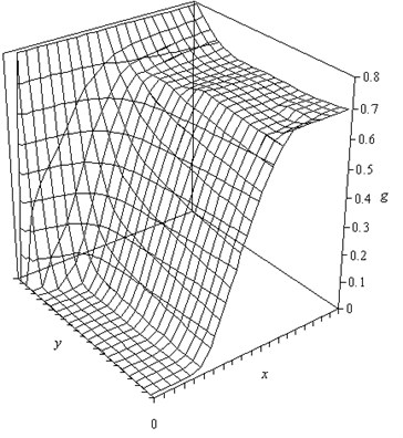
By hydrates is deposited on the pipe wall. On the border of the output set “soft” conditions, consistent with the vanishing of the second derivatives of all variables.
The system of equations is solved numerically Patankar’s SIMPLE [2]. The distribution of content of the gas hydrates in the cross section and length of the pipe obtained by calculation, shown in Fig. 1.
We consider a section of pipe at an inlet pressure of 0.5 MPa. A characteristic feature of the course is the existence of conditions for the formation of hydrates in the wall region, even in the initial section of the pipe. With increasing distance of hydrate formation zone is expanded and extends to the entire cross section of the tube. Humidity gas decreases as the water binding hydrates. The inhomogeneous distribution of the content of hydrates of the pipe section, the results obtained by the two-dimensional gas-dynamic calculations significantly affects the nature of the hydrate deposits on the pipe walls. Primarily hydrates are formed in the vicinity of the wall. The low velocity of the gas in the laminar sublayer and a high content of gas hydrates in the hydrate promote sticking to the wall.
2. The mathematical model of non-equilibrium flow of natural gas from the condensed phase in the channels of complex shape
Besides the effect of deposits on the walls of pipes, the solid particles can have an abrasive effect on the structural elements and measuring the gas shutoff apparatus. The condensed phase in the flow of natural gas hydrates in addition may contain other particulate matter (scale, sand, etc.). The assessment of such effects can be carried out on the basis of solving the equations of motion of a two-phase mixture in the pipeline elements.
The equations for the dispersed phase recorded in the curvilinear coordinate system [1]:
where the index belongs discontinuous phase; , – heat capacity and density of the material drops; – the number of condensed particles in unit volume; , – coefficients of resistance and heat transfer between phases, is given by [2]:
To solve the equations that describe the movement of particles, constructed difference scheme that monitors the flow direction. To solve the differential equations used a two-level iterative process. As an initial approximation for the particle velocities are taken of the gas velocity. A numerical method allows the calculation of the velocity field of the gas and particulate phase, the trajectories of particle motion, the mass flow of particles deposited on the walls.
The motion of the gas phase was calculated at a Reynolds number 50000. The vector velocity field is shown in Fig. 2.
Fig. 2The velocity field in the curved section of the pipe
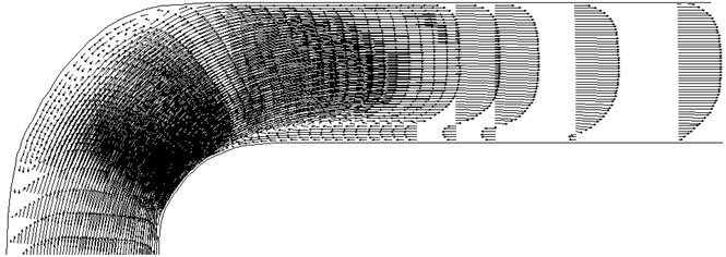
As follows from the results of calculations, the flow field is not symmetric. First, during urged toward the small radius wall and then in the opposite direction. As a result, the flow deflection from the center of a vortex flow as shown in Fig. 2. The velocity profile is characteristic of turbulent profile.
Particle motion is calculated for an equivalent particle diameter from 10 to 500 microns. The trajectories of the particles are shown in Figure 3. Small particles (10 microns) is monitored line current and the gas phase with the walls of virtually interacting. Larger particle diameter of 100 microns collide with the wall of the pipe after the bend.
Fig. 3The trajectories of particles with a diameter of 300 microns
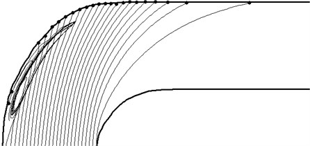
Large particles (300 and 500 microns) have a straight path for bending the pipe portion collide with the wall, and with high intensity. Low-velocity particles of 300 microns can be trapped vortex flow of gas and is in it for some time. Large particles with a diameter 500 microns almost all come through the vortex. Only particles from the wall region with a very low speed to make a whirlwind return movement.
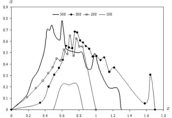
As a result of solving the problem of the motion of a two-phase mixture of particles and gas pipes are designed curved portion of the mass flow of the wall falling on particles of different sizes. Fig. 4 shows the distribution of the mass flows of precipitating particles in several sizes. Coordinates is measured on the wall of the pipe. Mass flow is related to the mass flow rate of particles on a straight section of the pipe (). These data can be used to assess mechanical action of the particles on the pipeline wall at different degrees of drying of natural gas.
Fig. 4Distribution of mass flows deposited particles on the pipe walls
3. Conclusions
A model of hydrate formation during the flow channels of raw gas, based on the equations of hydrodynamics and heat transfer in axisymmetric. Accounting for two-dimensional effects of hydrate formation allows to specify the start of hydrate formation in pipelines, the relative deviation of the one-dimensional calculation of two-dimensional averaged 100 %.
A method for evaluating loss of the condensed phase in the movement of natural gas, using the results of the joint numerical solution of the equations for the gas and condensed phases in the two-dimensional formulation. Calculation of the particle trajectories in the processing equipment indicates to the possibility of abrasion or parts located in the flow or intense sticking and accumulation of condensed phase (hydrate).
References
-
Sekundov A. N. Application of differential equations for the turbulent viscosity and analysis of non-self-plane movements. Mathematical Institute of USSR Academy of Sciences, Fluid Dynamics, Vol. 5, 1971, p. 114-127.
-
Patankar S. Numerical Methods for Solving Problems of Heat Transfer and Fluid Dynamics. Energoizdat, 1984, p. 150.
About this article
