Abstract
Bending presents a special case to microslip. Unlike that of axial loading on tangential joints where the microslip begins at the onset of the tangential load [1-3], the microslip for bending of layered structures (e.g. lap joints) occurs only once the shear stresses at the interface are overcome. These shear stresses are dependent on both the externally applied compressive forces and, more importantly for microslip, the forces created through the interface reactions caused through bending [4]. In this paper, a stiffness model is firstly introduced that defines the contact pressure along an interface for a joint that contains a uniform compressive force coupled with a tip force. The model is then used in a proposed bending microslip model to identify the magnitude of energy dissipation for various parameters. Lastly, a comparison is made between the analytical model and a numerical model using finite elements showing agreement.
1. Introduction
The use of finite elements (FEs) to solve bending microslip has been achieved with high accuracy for various applications in a range of industries (e.g. automotive and aerospace thin panels). However, the use of FEs results in generally relatively large models related to the highly dense contact mesh that is required (to account for the interface contact mechanics correctly) and for the large number of substeps (or timesteps) that are necessary for highly nonlinear dynamic problems. For a system with several layers, this could easily become computationally prohibitive. Therefore, an analytical model is sought, to resolve this limitation, and is presented in this paper.
2. Mathematical model
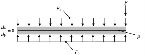
In this paper a two layer layered beam structure is considered. The beams are clamped to one another through boundary conditions using an evenly distributed force. Cantilever (fixed-free) boundary conditions and a tip force are applied to the structure. The material for each layer of the structure are identical throughout and a constant friction coefficient is considered at the interface. This is shown in Fig. 1.
Fig. 1Layered structure containing 2 layers with loads and boundary conditions applied
When a layered structure is exposed to bending there are three possible states: sticking, microslip (stick-slip) and macroslipping. When sticking occurs there is no motion at the interface. When macroslipping occurs all points along the interface are in motion. When microslip occurs, there is a combination of both sticking and portions of macroslipping. To be able to describe this motion, and when the various statuses occur, the initiation tip force for the microslip and the initiation force for the total structure macroslip need to be determined. Knowing that when the layers are sticking to one another that the second area moment of inertia can be described as:
where the subscript is the number of layers, is the width of each layer, is the thickness of each layer. When the layers are slipping relative to one another, the second area moment of inertia takes on a slightly different form which can be defined as:
Knowing Eq. (1), the upper limit of force of when the microslip becomes exhausted throughout the interface is described by:
where is the total compressive force, is the friction coefficient, is the length of each layer and is the distance from the neutral axis of the structure to the interface. To find the lower limit of force of when the microslip is initiated is given as:
Once the upper and lower limits of microslip forcing region is defined, the distribution of this force needs to be found per unit of structure length not only for but also for the expansion of the tip force, . This is done by artificially descretising the structure into elemental regions that determine the status of the contact. The distribution of is dependent on a distribution constant given by:
where is the summation of the elements length up to a particular element of interest, the subscript is the element number and is the average modulus of elasticity. Using Eq. (5), the distributed force from for the nodes of the elemental regions is described as:
Knowing Eq. (6), the relative force distribution for each element are simply given by:
From Eq. (7), the tip force required to make each element begin to slip is described as:
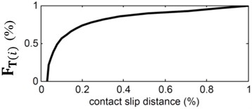
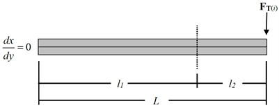
In layered structures, the slipping occurs firstly where the structure displacement is greatest. Once slipping is initiated it then propagates along the length of the interface until the constrained end is reached [5]. This is due to the imbalance in the compressive force from the equivalent distributed force of . As the slipping propagates along the length of the contact, there exists both sticking and slipping domains. Both the contact slipping propagation and the sticking and slipping domains are illustrated in Fig. 2.
Fig. 2a) Contact slip propagation from FTi and, b) layered structure sticking (l1) and slipping (l2) domains from applied FTi
a)
b)
The displacements for and are described by:
The total displacement during microslip is simply the summation of and .
3. Finite element model
ANSYS commercial FE code is used as the FE solver. Two important parameters specifically for the FE model are the contact element descretisation and the substep (or timestep) descretisation. Both of these are highly dependent on the level of descretisation and must be large enough in quantity. The contact descretisation was limited to 1/100th of . Contact pairs consisting of contact (CONTA174) and target (TARGE170) elements are used to provide interaction between the layers through the implementation of Coulomb friction. The interpretation of Coulomb friction for ANSYS is that the product of the force normal to the sliding direction and the friction coefficient is a limiting force. If the tangential force is less than the limiting force the state of the contact is sticking. However, if the tangential force is equal or greater than the limiting force then the contact is sliding producing relative motion. An augmented Lagrange contact formulation is used to help with convergence whereby the pressure and frictional stresses are augmented during the equilibrium iterations resulting in the final contact penetration being decreased and lower than the user-defined allowable penetration. The substep descretisation used was limited to 1/400th of . In addition to these two parameters, the number of elements throughout the thickness must be appropriate. This is because the contact stresses are what determines the stick-slip state of the contact. Since stresses are calculated at Gauss integration points and extrapolated to the nodes using shape functions, a higher accuracy can be achieved when using greater than one element. For these simulations presented, 3-D solid higher-order hexahedron (SOLID186) and 2-D contact elements with approximately 12000 degrees of freedom was used. Each layer contained three elements throughout the thickness. Going from a single element to three elements has shown in these simulations to reduce the error in the contact shear stress from approximately 18 % to < 1 %.
4. Results
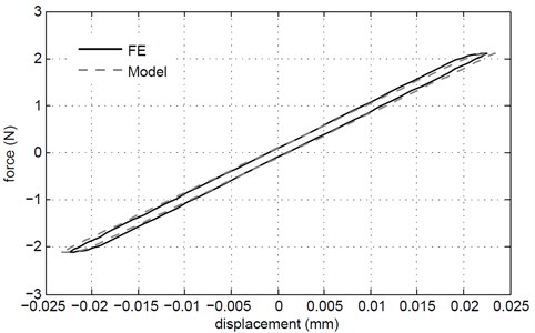
A comparison is made between the FE model and the analytical model in Fig. 3. It is shown that both are in good agreement. Table 1 depicts the various parameters used in the models, the corresponding dissipated energy and the error between the FE model and the analytical model.
Fig. 3Force-displacement hysteresis loop comparison between FE and Model for
From Table 1, it can be concluded that as the thickness, , of each layer decreases, the energy dissipation, , increases. This would be expected as the displacement is likely to increase. It can also be said that as the friction coefficient decreases so does . This would be expected in that would also decrease since the shear stress needed to overcome friction is reduced. It however is not apparent of how the modulus of elasticity, , affects . This appears to fluctuate slightly and could be from a local minima/maxima value that has been reached or not using a sufficiently descretised contact mesh.
Table 1Parameters and dissipated energy for FE model and analytical model
Run | (mm) | (mm) | (mm) | (MPa) | FE (mJ) | Model (mJ) | Error % | |
1 | 30 | 200 | 8 | 2.07E+05 | 0.80 | 0.0344 | 0.0364 | 5.7 |
2 | 30 | 200 | 8 | 3.10E+05 | 0.80 | 0.0127 | 0.0137 | 7.8 |
3 | 30 | 200 | 8 | 1.38E+05 | 0.80 | 0.0298 | 0.0313 | 5.1 |
4 | 30 | 200 | 8 | 6.89E+04 | 0.80 | 0.0595 | 0.0625 | 5.1 |
5 | 30 | 200 | 6 | 2.07E+05 | 0.80 | 0.0454 | 0.0495 | 9.1 |
6 | 30 | 200 | 4 | 2.07E+05 | 0.80 | 0.0429 | 0.0467 | 8.8 |
7 | 30 | 200 | 2 | 2.07E+05 | 0.80 | 0.1007 | 0.1071 | 6.3 |
8 | 30 | 200 | 8 | 2.07E+05 | 0.65 | 0.0286 | 0.0292 | 2.4 |
9 | 30 | 200 | 8 | 2.07E+05 | 0.50 | 0.0225 | 0.0242 | 7.5 |
10 | 30 | 200 | 8 | 2.07E+05 | 0.25 | 0.0103 | 0.0104 | 1.2 |
5. Conclusions
An analytical model has been presented that can be used for bending microslip for cantilever type structures. Varying parameters were used to determine the effect that they would have on the overall accuracy of the proposed model. Although there are some differences, both the FE model and the analytical model are in good agreement.
References
-
Xiao H., Shao Y., Xu J. Investigation into the energy dissipation of a lap joint using the one-dimensional microslip friction model. European Journal of Mechanics A/Solids, Vol. 43, 2014, p. 1-8.
-
Cigeroglu E., Lu W., Menq C.-H. One-dimensional dynamic microslip friction model. Journal of Sound and Vibration, Vol. 292, 2006, p. 881-898.
-
Lord C., Rongong J. A tangential microslip model for circularly and elliptically loaded structures. Noise and Vibration – Emerging Technologies, Croatia, 2015.
-
Lord C., Rongong J., Hodzic A. The behaviour of naturally debonded composites due to bending using a meso-level model. Applied Composite Materials, Vol. 19, Issues 3-4, 2011.
-
Lord C., Rongong J. A single layer constitutive model for the dynamics and vibration damping of layered built-up structures using microslip and macroslip models. 54th AIAA/ASME/ASCE/AHS/ASC Structures, Structural Dynamics, and Materials Conference, USA, 2013.
About this article
