Abstract
The paper presents modelling and analysis of crankshaft system. At the beginning some general information about the torsional vibration dampers is shown. Moreover, the principle of work and models of some types of dampers are presented. The next section demonstrates techniques of modelling of crank-piston mechanism with dynamic eliminator of vibrations. Furthermore, chapter shows dynamic equations of analysed system. After that, there are results of numerical simulations and experiments. At the end, the whole paper is summarized by synthetic conclusions about modelling and analysis of crankshaft systems with vibration dampers.
1. Introduction
Modern drive systems are becoming lighter and more strenuous. Mass reduction connected with the use of modern materials influences positively reduction of the costs of using and utilization of the object. It also limits the emission of harmful substances.
Of course, such changes have a significant impact on the dynamics and statics of the object. Significant change of vibration structure of the object is possible [1, 2]. Therefore, there arises a question, how will the spectrum of device vibration change with the introduction of design changes? Furthermore, it is interesting if there exists a possibility of shaping the spectrum of vibrations of the machine.
In practice, dampers of torsional vibrations are often used to modify the vibration structure. Experiments show that the use of eliminator of torsional vibrations influences other degrees of freedom thanks to lateral-torsional coupling. Therefore, there is an idea of using this phenomenon for analysis and even for shaping the character of transverse vibrations of the system. This concept seems to be especially interesting in case of crank systems of car engines, where dampers of torsional vibrations are very popular [3].
2. Torsional vibration dampers for piston engines
Torsional vibration dampers used in piston engines, usually operate like dynamic vibration eliminator. This means that the reduction of vibrations amplitude does not occur by dissipation of energy, but by moving away the resonance frequencies from the frequency excitation forces. Such a damper is an additional inert element of the system, which is connected to the whole in a flexible way. In practice, the use of dynamic eliminator of vibrations means an increase in the number of degrees of freedom, which is equivalent to a change in spectral structure of the whole device. Proper selection of the parameters of a damper allow to change the frequency of free vibrations in a wide range.
In most practical solutions of torsional vibration dampers with a proper approximation there can be used a model consisting of a system of rigid bodies connected by elastic connectors. Connecting elements usually have elastic properties, damping may be omitted in many cases. Therefore, a dynamic model presented below may be proposed for essential industrial and automotive applications of dampers [4]:
where: – vector of generalized coordinates of torsional vibration damper, – inertia matrix of torsional vibration damper, – operator of the right side of equation of dynamics of torsional vibration damper.
In case of the simplest solution of torsional vibration eliminator which is a disk elastically connected with the crankshaft. Such a system is shown schematically in Fig. 1.
Fig. 1The structural model of the torsional vibration damper: 1 – hub, 2 – torsional spring, 3 – flywheel of damper
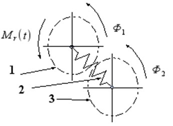
In this case (Fig. 1), the dynamic model Eq. (1) has the following form of differential equations system:
where: – mass moment of inertia of the hub, – mass moment of inertia of damper flywheel, – stiffness of elastic connector (torsional spring), – the reaction moment of the crankshaft.
Wideband damper of torsional vibrations is a more complex solution. The principle of operation of this device does not change. However, there is an extra degree of freedom allowing for additional changes in the spectral structure of damped system. Such a damper is shown schematically in Fig. 2.
Fig. 2The structural model of the widerange damper of torsional vibration: 1 – hub, 2 – torsional sprint, 3 – flywheel of damper, 4 – torsional spring of second flywheel, 5 – second flywheel
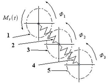
Damper of this type (Fig. 2) describes the following system of equations:
where: – mass moment of inertia of a second flywheel of damper, – stiffness of the elastic connector of the second degree (torsional spring).
3. Dynamic model of crank system
The dynamics of a seemingly simple crank system is very complex. The main reason is a complicated geometry of the motion of the parts of the mechanism and a very complex character of deformation of the crankshaft. From the point of view of mechanics, the individual elements of this system should be treated as continuous structures with given distributions of density and stiffness tensor. In practice, such an analysis would be very difficult, even impossible. Therefore, the mechanism is most often presented as a series of stiff elements (material points or rigid bodies) connected by a weightless continuous system. It is possible to present the crank system precisely in the way presented in Fig. 3.
Fig. 3The model of the crankshaft of one piston: 1 – flywheel, 2 – crankshaft, 3 – torsional vibration damper
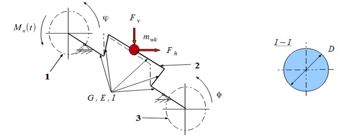
To describe the dynamics of the proposed model, it is convenient to introduce the following generalized coordinate system (Fig. 3): – rotation angle of flywheel of the engine, – rotation angle of the disk of torsional vibration damper, –horizontal deformation of the crank, – vertical deformation of the crank:
It can be seen that equations of motion of analysed crank mechanism with an attached torsional vibration damper are strongly coupled nonlinear equations of the second order. Of course, there do not exist any solutions of this system in the closed form [5]. However, it is possible to find analytic approximate solution of this problem or integrate the system Eqs. (8)-(12) with numerical methods.
4. Numerical solution and research results
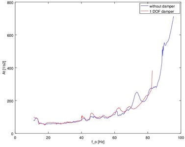
As noted above, it is possible to find a solution to the system of Eqs. (8)-(12) by numerical way. Runge-Kutta 4-5 and Adams methods were used for integrating in the case of a discussed case. This decision is directly connected with high precision of both methods. The method allowing for a faster analysis with maintaining the expected precision of the results was specified. Additionally, the experimental results of the research of real combustion engine were presented (Fig. 5). Spectra of vibration accelerations obtained in experiment and by the simulation (Fig. 4) have a similar frequency structure.
It can be said that a proposed model may be successfully used to describe piston engines which are used in practice.
Fig. 4The spectra of torsional vibration accelerations of the model of crank system with dampers
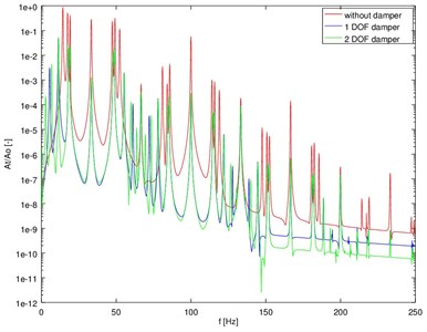
Fig. 5Registered amplitude characteristics of torsional vibration accelerations of the damper
5. Conclusions
Crank systems are the basis for the construction and operation of most combustion engines. The trend to reduce the mass of any construction may cause significant changes in the dynamics of the device. Discussed crank systems are very sensitive to such type of innovations. The reason for this is the relatively low stiffness of the mechanism. Therefore, detailed analysis of its dynamics is necessary. Effective use of model of elastic shaft is possible in the problem of dynamics of crank mechanism.
The simulations clearly indicate that the use of torsional vibration dampers allows to reduce the level of vibration system. Moreover, the experimental research confirms obtained results.
The analysis of obtained system of equations indicates the existence of a strong coupling between the equations of lateral and torsional vibrations resulting in the transfer of energy between the particular degrees of freedom. This implies the relation between the spectral structure of bending and angle vibrations. It allows to assume that the basic frequencies of spectrum of a discussed object (frequencies of natural vibrations of linear part of a discussed system) will be identical without maintaining the same amplitudes. The reason for this fact is the character of coupling appearing in the system, which is characterized by a significant nonlinearity. It should be emphasized that the mutual relation between the structure of bending and torsional vibrations, sensitive to any changes in the technical condition of the analyzed mechanism can be a valuable source of diagnostic information [1, 3, 5].
References
-
Desbazeille M., Randall R. B., Guillet F., El Badaoui M., Hoisnard C. Model-based diagnosis of large diesel engines based on angular speed variations of the crankshaft. Mechanical Systems and Signal Processing, Vol. 24, 2010, p. 1529-1541.
-
Charles P., Sinha J. K., Gu F, Lidstone L., Ball A. D. Detecting the crankshaft torsional vibration of diesel engines for combustion related diagnosis. Journal of Sound and Vibration, Vol. 321, 2009, p. 1171-1185.
-
Dabrowski Z., Zawisza M. Investigations of the vibroacoustic signals mechanical defects sensitivity is not recognized by the OBD system in diesel engines. Solid State Phenomena, Vol. 180, 2012, p. 194-199.
-
Deuszkiewicz P., Pankiewicz J., Dziurdź J., Zawisza M. Modeling of powertrain system dynamic behavior with torsional vibration damper. Advanced Materials Research, Vol. 1036, 2014, p. 586-591.
-
Chiliński B. Analysis of disturbance torque influence on critical state in rotational systems. Transportation Problems, Vol. 8, Issue 4, 2013, p. 137-146.
About this article
