Abstract
The membrane disc coupling has the ability to transmit higher power under high-speed rotation. It also has the ability of compensation angular and radial displacement. The finite element model of the coupling was established and vibrational characteristics were analyzed. The modal experiments were carried out with hammering method, the modal parameters were obtained and the correct of the simulations was verified under the same constraints with the FEM model. The results showed that simulating results agreed well with that of the experiments.
1. Introduction
The coupling is applied to join two rotary shafts, so as to transfer torque and power. The membrane disc coupling has the ability of transmitting high power under high rotating speeds. The strength of the membrane disc coupling has important influence on the reliability of the transmission system [1]. According to the working conditions of the transmission shaft, numerical and experimental research were carried out in this paper. The main contents are listed as following:
1) The natural frequency and natural modes were calculated for the membranous disc coupling in different boundary conditions in order to obtain the dynamic characteristics of the membrane disc coupling and provide the basis for its safe application.
2) The modal test was carried out with the pulse exciting (hammering) method for the coupling, and the natural frequency and natural mode were measured in order to obtain actual structure dynamic characteristics of the coupling.
3) The dynamic characteristics were compared and analyzed between the numerical and experimental results, the effectiveness and credibility of the numerical simulation were examined.
2. Simulation
2.1. The finite element model
The membrane disc coupling was completely symmetrical, so the model can be established from a two-dimensional model. The membrane disc coupling structure was shown as Fig. 1. The two-dimensional model was established in X-Y plane, and its 1/4 model was shown as Figure 2. The 3D model was shown as Figure 3. The three-dimensional model was meshed with SOLID45. The meshed model consisted of 49024 elements and 64448 nodes. According to the structure conditions, calculation and analysis were carried out respectively under free-free and clamped-clamped conditions for the coupling model [2-4].
2.2. Simulating results
2.2.1. Free-free boundary condition
Two installation edges of the coupling were not imposed any constraints. Natural frequencies and modes were shown as Table 1.
Fig. 12-D model
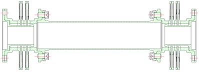
Fig. 33-D model
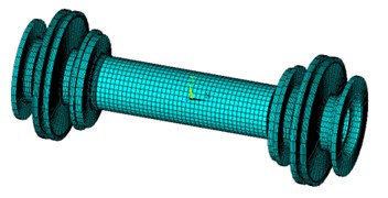
Fig. 22-D model(1/4)

Table 1Natural frequency and natural mode of free – free boundary condition
Order | 1 | 2 | 3 |
Natural frequency | 0 | 0 | 0 |
Mode shape |  |  | 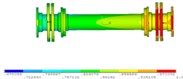 |
Order | 4 | 5 | 6 |
Natural frequency | 0 | 0 | 0 |
Mode shape | 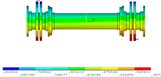 | 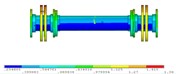 | 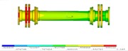 |
Order | 7 | 8 | 9 |
Natural frequency | 110.76 | 116.17 | 116.17 |
Mode shape | 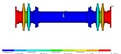 | 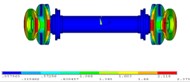 | 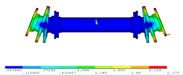 |
Order | 10 | 11 | 12 |
Natural frequency | 130.36 | 130.36 | 143.91 |
Mode shape | 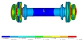 | 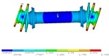 | 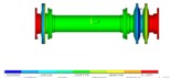 |
Order | 13 | 14 | 15 |
Natural frequency | 398.59 | 412.16 | 443.31 |
Mode shape | 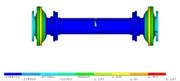 | 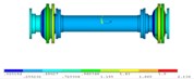 | 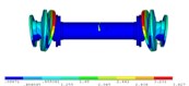 |
Order | 16 | 17 | 18 |
Natural frequency | 443.31 | 451.19 | 451.19 |
Mode shape | 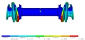 | 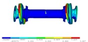 | 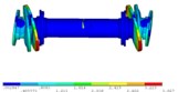 |
Order | 19 | 20 | |
Natural frequency | 637.42 | 637.42 | |
Mode shape | 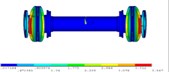 | 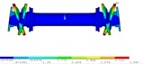 |
The results were summarized as following:
1) Since no degrees of freedom were constrained, the first six modes were rigid modes.
2) There were multiple sets of two adjacent or same natural frequencies but with the same mode shapes oriented to different directions. It shall be considered as the same order because the structure was completely symmetrical. It was consistent with the results of theoretical solution
3) Vibration modes of 8th-11th and 15th-20th were local vibration. The 7th, 12th, 13th and 14th modes were transverse vibration.
2.2.2. Clamped-clamped boundary condition
The X, Y, Z three directions were constrained the node of two installation edges of the coupling. It was called clamped-clamped boundary condition, which was shown as Fig. 4. Natural frequencies and modes were shown as Table 2.
Fig. 4Clamped-clamped
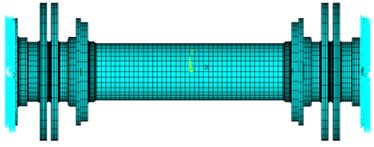
Table 2Natural frequencies and natural modes of clamped-clamped boundary condition
Order | 1 | 2 | 3 |
Natural frequency | 79.394 | 298.01 | 298.01 |
Mode shape | 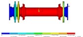 | 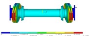 | 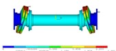 |
Order | 4 | 5 | 6 |
Natural frequency | 343.99 | 343.99 | 361.79 |
Mode shape | 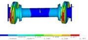 | 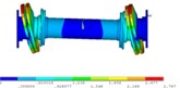 | 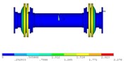 |
Order | 7 | 8 | 9 |
Natural frequency | 378.72 | 601.75 | 601.75 |
Mode shape | 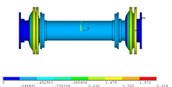 | 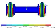 | 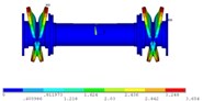 |
The results were summarized as following:
1) There were multiple sets of two adjacent or same natural frequencies but with the same mode shapes oriented to different directions. It shall be considered as the same order because the structure was completely symmetrical. It was consistent with the results of theoretical solution.
2) The vibrating modes of 1st, 6th and 7th orders were axial.
3) Lateral vibration of the entire shaft was excited by vibrations of membrane disc in the same direction on both sides for the 2nd and 3rd orders, and it was vibrations of the membrane disc in reverse direction on both sides for the 4th and 5th orders. There was transverse vibration of the membrane disc, and the shaft lies between discs did not vibrate.
3. Modal test and analysis
3.1. Test introduction
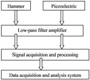
There are three aspects for modal test, namely, excitement, measurement and analysis. Connection of instruments test structure was shown in Figure 5.
Fig. 5Instrument connection diagram
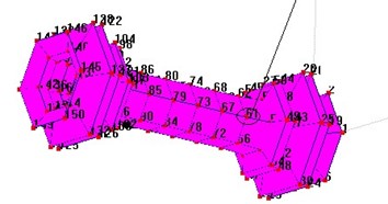
The simulation results were verified by the modal test with hammering method [5-7]. The geometric structure, which had 150 geometric points, was shown as Fig. 6 for the membrane disc coupling basing on experiment scheme.
Fig. 6Test model
3.2. Test results
3.2.1. Free-free state
The results were shown as Table 3.
Table 3Test results of free – free boundary condition
Order | 1 | 2 | 3 |
Natural frequency | 106.432 | 121.356 | 449.679 |
Damping ratio (%) | 0.364 | 0.344 | 0.118 |
Mode shape |  |  | 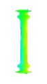 |
Order | 4 | 5 | 6 |
Natural frequency | 462.643 | 664.312 | 670.176 |
Damping ratio (%) | 0.123 | 0.265 | 0.236 |
Mode shape | 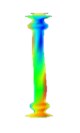 | 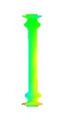 | 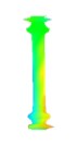 |
3.2.2. Clamped-clamped state
The results were shown as Table 4.
Table 4Test results of clamped-clamped boundary condition
Order | 1 | 2 | 3 |
Natural frequency | 278.035 | 320.375 | 371.185 |
Damping ratio (%) | 3.720 | 1.642 | 0.684 |
Mode shape | 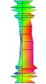 | 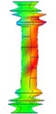 | 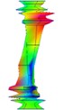 |
Order | 4 | 5 | |
Natural frequency | 1202.715 | 1447.613 | |
Damping ratio (%) | 1.225 | 2.551 | |
Mode shape | 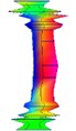 |  |
4. Conclusions
1) The modal parameters and mode shapes were obtained by modal test, and natural frequencies were basically agreed with the simulating results under the same constraints. The relative error was less than 10 %. The accuracy of numerical simulation was verified.
2) It was consistent with theoretical analysis that the error of the modal frequency gradually increased from low to high order.
3) The critical speeds of the first five orders were deduced according to the relation between the critical speed and natural frequency . The resonance would not occur in the range of operating speeds for the membrane disc coupling.
References
-
Li Xiaopeng, Yao Hongliang, Sun Wei, Wen Bangchun Influence analysis of membrane coupling to rotor system dynamic characteristics. Journal of Mechanical Strength, Vol. 28, Issue 3, 2006, p. 322-326, (in Chinese).
-
Piegl L. Modeling the shape of rational B-spline part, Surfaces Computer Aided Design, Vol. 21, Issue 9, 1989, p. 538-546.
-
Zhang HaoMin, Zhou XinGuang, Wen ZhiMin Account of flexibility metal membrane coupling design. Mechanical Research and Application, Vol. 16, Issue 3, 2003, p. 54-55, (in Chinese).
-
Bi ChengWu Analysis of strength and vibration of membrane coupling. Ship Technology of other Country (Turbine Boiler), Vol. 6, 1981, p. 9-14, (in Chinese).
-
Sparbhakar Sekhar A. S., Mohanty A. R. Crack versus coupling misalignment in a transient rotor system. Journal of Sound and Vibration, Vol. 256, Issue 4, 2002, p. 773-786.
-
Johnson C. M., Eng B. C., Mech M. I. The characteristics of multiple membrane couplings. World Pumps, Vol. 12, 1996, p. 14-15.
-
Wang Zhaofu Characteristics and application of membrane coupling. Science Technology of Ship, Issue S1, 1997, p. 45-61, (In Chinese).
About this article
