Abstract
Plane vibrations of a two dimensional elastic structure are investigated in this paper. Vibrations taking place according to the eigenmode are represented by using the method of stroboscopic geometric moiré. Selection of number of gaps when using the superimposed moiré technique is investigated and recommendations for choosing of their number are provided.
1. Introduction
Plane vibrations of a two dimensional elastic structure are investigated in the paper. Vibrations taking place according to the eigenmode are represented by using the method of stroboscopic geometric moiré. In this paper the superimposed moiré technique is used and selection of the number of gaps when using the superimposed moiré technique is investigated. Recommendations for choosing of the number of gaps are provided.
This paper is the continuation of investigations presented in [1]. Similar problems are investigated in [2-14] and other related papers.
2. Theoretical investigation of the stroboscopic measurement of vibrations
One dimensional problem is investigated. In the previous paper when investigating the one dimensional model it was assumed that moiré lines are in the status of equilibrium and in the deflected state. But when performing stroboscopic measurement of vibrations taking place according to the eigenmode usually the images of the structure at both positions of extreme deflections are used. Here the one dimensional model corresponding to this problem is investigated.
Moiré lines in the deflected in the negative direction state are represented as:
where is the coordinate, determines the width of moiré lines, is the intensity of the image, is the displacement. In the investigation it is assumed that when deflection is in the negative direction:
where is a constant.
Moiré lines in the deflected in the positive direction state are represented as:
where is the intensity of the image, is the displacement. In the investigation it is assumed that when deflection is in the positive direction:
Intensity of the stroboscopic image is represented in the usual way:
Here gaps between moiré lines are assumed. In the previous paper the following special function was introduced:
where 0, 1, 2,… is the width of the gap.
Moiré lines in the deflected in the negative direction state are represented as:
Moiré lines in the deflected in the positive direction state are represented as:
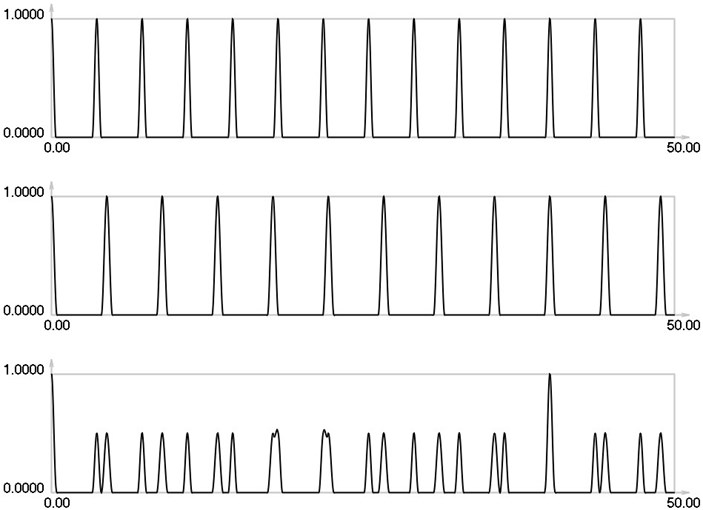
Further it is assumed that 0.8 and 0.1. , and for 0,1,…, 4 are presented in Figs. 1-5.
Fig. 1I1, I2 and Is for i= 0
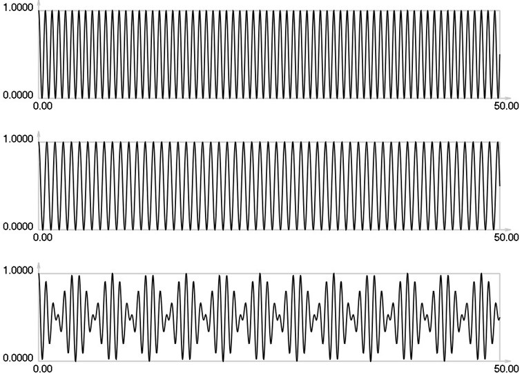
Fig. 2I1, I2 and Is for i= 1
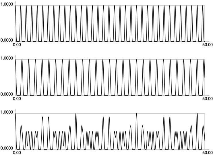
Fig. 3I1, I2 and Is for i= 2
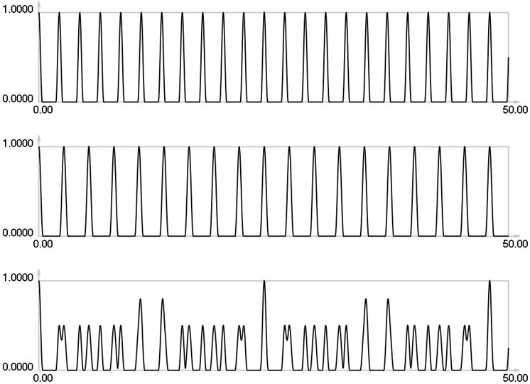
As seen from the results for 0 envelope of the stroboscopic image has 13 maximums inside the analyzed interval. From the results for 1 it is seen that the envelope of the stroboscopic image has 7 maximums inside the analyzed interval. From the results for 2 it is seen that the envelope of the stroboscopic image has 5 maximums inside the analyzed interval. From the results for 3 it is seen that the envelope of the stroboscopic image has 4 maximums inside the analyzed interval. From the results for 4 it is seen that the envelope of the stroboscopic image has 2 maximums inside the analyzed interval. Thus from the presented results it can be concluded that with the increase of the width of the gap the intervals between the maximums of the envelope of intensity of the stroboscopic image increase. This enables to interpret the displacements from moiré images with gaps.
Fig. 4I1, I2 and Is for i= 3
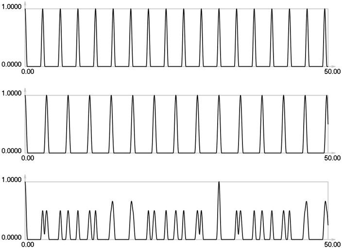
Fig. 5I1, I2 and Is for i= 4
3. Conventional stroboscopic geometric moiré images of vibrating elastic structure for different numbers of gaps
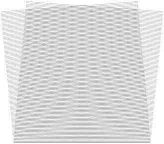
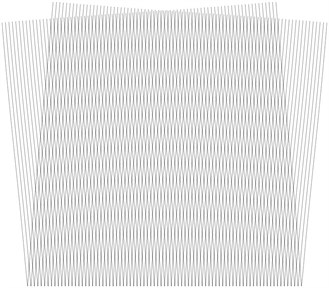
Square elastic structure with fixed lower boundary is analyzed. Stroboscopic geometric moiré images for the two conventional directions of fringes for the first eigenmode are shown. When the gap width is 1 the images are shown in Fig. 6. When the gap width is 2 the images are shown in Fig. 7. When the gap width is 3 the images are shown in Fig. 8. When the gap width is 4 the images are shown in Fig. 9.
Fig. 6Stroboscopic geometric moiré images when the gap width is i= 1
a) The first direction of fringes
b) The second direction of fringes
Fig. 7Stroboscopic geometric moiré images when the gap width is i= 2
a) The first direction of fringes
b) The second direction of fringes
Fig. 8Stroboscopic geometric moiré images when the gap width is i= 3
a) The first direction of fringes
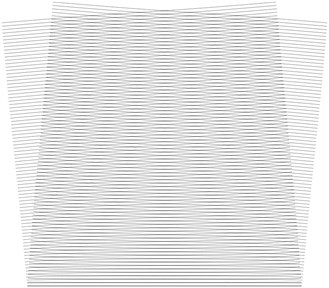
b) The second direction of fringes
Fig. 9Stroboscopic geometric moiré images when the gap width is i= 4
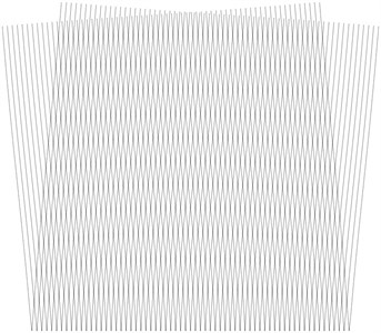
a) The first direction of fringes
b) The second direction of fringes
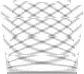
4. Superimposed moiré images of vibrating elastic structure for different numbers of gaps
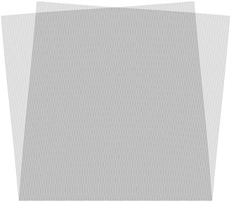
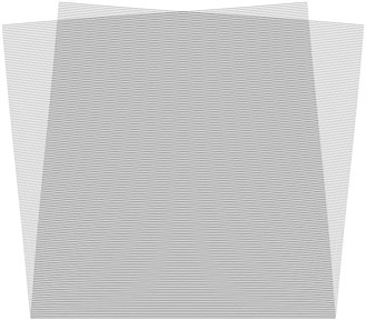
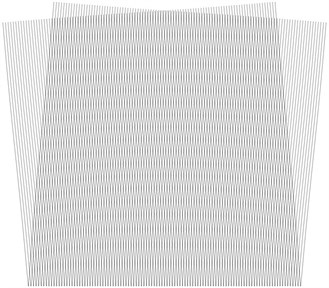
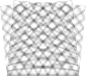
Superimposed stroboscopic geometric moiré images for the first eigenmode are shown. When the gap width is 1 the images are shown in Fig. 10. When the gap width is 2 the images are shown in Fig. 11. When the gap width is 3 the images are shown in Fig. 12. When the gap width is 4 the images are shown in Fig. 13.
Fig. 10Superimposed stroboscopic geometric moiré image when the gap width is i= 1
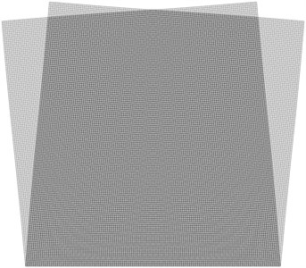
Fig. 11Superimposed stroboscopic geometric moiré image when the gap width is i= 2
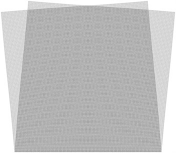
Fig. 12Superimposed stroboscopic geometric moiré image when the gap width is i= 3
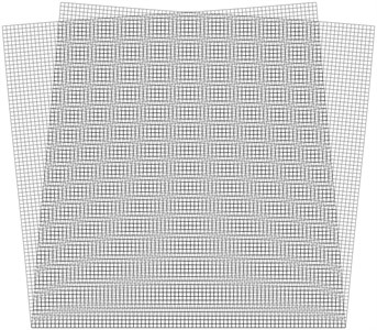
Fig. 13Superimposed stroboscopic geometric moiré image when the gap width is i= 4
From the presented results it is seen that with the increase of the number of gaps there is a smaller number of moiré fringes and the accuracy of measurement deteriorates. But in order to be able to interpret both systems of moiré fringes simultaneously there are to be sufficient gaps. From the presented results the gap width 2 is recommended.
5. Conclusions
The superimposed moiré technique is used to represent both moiré images for the analysis of plane vibrations of two dimensional elastic structures at the same time. From the presented investigation it is seen that with the increase of the number of gaps there is a smaller number of moiré fringes and the accuracy of measurement decreases. But in order to be able to interpret both systems of moiré fringes simultaneously there must be sufficient gaps. From the presented investigations the gap width 2 is considered to provide the best results.
The recommendations for the choice of the number of gaps using the technique of superimposed moiré for the analysis of plane vibrations of two dimensional elastic structures are applicable for the investigation of vibrations of precise mechanical devices.
References
-
Maskeliūnas R., Ragulskis K., Paškevičius P., Patašienė L., Pauliukas A., Ragulskis L. Measurement of plane vibrations of a two dimensional elastic structure. Journal of Measurements in Engineering, Vol. 3, Issue 2, 2015, p. 42-47.
-
Ragulskis K., Maskeliūnas R., Zubavičius L. Analysis of structural vibrations using time averaged shadow moire. Journal of Vibroengineering, Vol. 8, Issue 3, 2006, p. 26-29.
-
Saunorienė L., Ragulskis M. Time-Averaged Moire Fringes. Lambert Academic Publishing, 2010.
-
Ragulskis M., Maskeliūnas R., Ragulskis L., Turla V. Investigation of dynamic displacements of lithographic press rubber roller by time average geometric moire. Optics and Lasers in Engineering, Vol. 43, 2005, p. 951-962.
-
Huimin X., Guotao W., Fulong D., Guangjun Z., Xingfu L., Fangju Z., Aiming X. The dynamic deformation measurement of the high speed heated LY12 aluminium plate with moire interferometry. Journal of Materials Processing Technology, Vol. 83, Issues 1-3, 1998, p. 159-163.
-
Deason V. A., Epstein J. S., Abdallah A. Dynamic diffraction moire: theory and applications. Optics and Lasers in Engineering, Vol. 12, Issues 2-3, 1990, p. 173-187.
-
Kokaly M. T., Lee J., Kobayashi A. S. Moire interferometry for dynamic fracture study. Optics and Lasers in Engineering, Vol. 40, Issue 4, 2003, p. 231-247.
-
Timoshenko S. P., Goodier J. N. Theory of Elasticity. Nauka, Moscow, 1975.
-
Soifer V. A. Computer processing of images. Herald of the Russian Academy of Sciences, Vol. 71, Issue 2, 2001, p. 119-129.
-
Vest C. Holographic Interferometry. Mir, Moscow, 1982.
-
Han B., Post D., Ifju P. Moire interferometry for engineering mechanics: current practices and future developments. Journal of Strain Analysis for Engineering Design, Vol. 36, Issue 1, 2001, p. 101-117.
-
Field J. E., Walley S. M., Proud W. G., Goldrein H. T., Siviour C. R. Review of experimental techniques for high rate deformation and shock studies. International Journal of Impact Engineering, Vol. 30, Issue 7, 2004, p. 725-775.
-
Dai F. L., Wang Z. Y. Geometric micron moire. Optics and Lasers in Engineering, Vol. 31, Issue 3, 1999, p. 191-198.
-
Liang C. Y., Hung Y. Y., Durelli A. J., Hovanesian J. D. Time-averaged moire method for in-plane vibration analysis. Journal of Sound and Vibration, Vol. 62, Issue 2, 1979, p. 267-275.
About this article
The authors thank the reviewers for their valuable comments which enabled to improve the paper.
