Abstract
This paper describes the results of the experimental studies of vibrations of one-mass system on an elastic suspension with two unbalanced vibrators in a wide range of excitation frequencies. The technique of the tests and results analysis is given. The paper shows that in a mechanical system an effect of self-oscillating adaptive self-synchronization of unbalanced masses takes place when changing the vibration forms of the carrier body, depending on the excitation frequency.
1. Introduction
Among the different classes of vibrating machines the machines with unbalanced exciters of the working body oscillations has received wide acceptance [1-4]. Depending on the configuration of the unbalanced vibrator one can get a wide variety of forms and trajectories of the working body movement. Of particular importance in this class of vibrators are the machines with self-synchronizing exciters.
The present work describes the results of the experimental studies of vibrations of a flat one-mass system with two unbalanced vibrators based on the elastic suspension. The aim of this work is to identify the main features of the dynamic processes occurring in the mechanical system with self-synchronizing vibrators in a wide range of excitation frequencies.
2. Description of the experimental setup
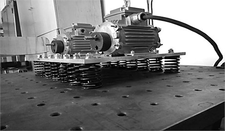
A general view of the experimental setup is presented in Fig. 1. A rigid metal plate of rectangular shape (platform) is horizontally installed on the 14 identical springs attached to a stationary base. The springs are spaced evenly in two rows (seven pieces in each row) along the longer faces of the plate, symmetrically about the axes of symmetry of the plate. On the platform two identical unbalanced vibrators of EV-320-4 type are installed also symmetrically and mutually parallel. Each of the vibrators is a three-phase asynchronous motor. Identical unbalanced masses (fixed eccentric disks) are set on both ends of the shafts of each motor. The motors connected to a joint frequency transducer of the three-phase current so that the rotors rotate in opposite directions.
The platform with motors may be considered as an absolutely rigid body on the elastic suspension. Therefore this mechanical system has six degrees of freedom. The main parameters of the setup are: the size of the plate 350×300×7 mm; the distance between the axes of rotation of the unbalanced vibrators – 236 mm; the distance between the planes of rotation of each unbalanced vibrator – 160 mm; the distance between the axes of rotation of the vibrators and the upper plane of the plate – 50 mm; the mass of the plate – 2 kg; the mass of one vibrator – 4.6 kg; the mass of one unbalance – 0.2 kg, adjusting eccentricity of 10 mm, the axial stiffness of one spring is 46.7 KN.
According to preliminary estimates the stiffness of the elastic system (if sequential loading) in vertical direction is equal to 327 KN/m and 614 KN/m in horizontal direction.
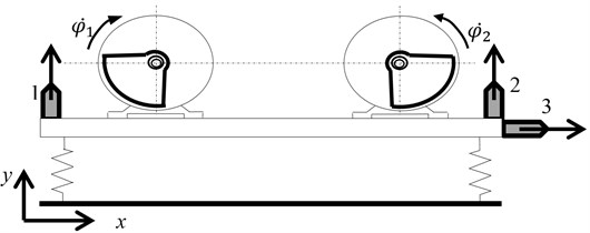
Fig. 1General view of the experimental setup
3. Measurement system
It is assumed that the experimental setup complies with all the signs of a centered balanced system, such as the symmetry of gravity action of the vibrators and the plate, of the springs response, and the symmetry of the planes of rotation of the unbalanced masses about the principal axes of the plate. This assumption suggests that the rotation of the imbalanced masses will excite the oscillations of the platform in the plane perpendicular to the axis of rotation of the imbalanced masses (Fig. 2). In order to measure the vibration parameters of the platform, three piezo accelerometers of KD-35 (RFT, Germany) type were set on the platform, two of which were upright oriented (number 1 and 2 in Fig. 2) and one was set horizontal (number 3 in Fig. 2). The chosen accelerometers layout allows the plane vibration of the platform to be measured in all possible directions in the plane of the disturbing forces action.
To measure the angular position of the unbalanced masses and the speed of their rotation the encoders of E40H8-2000-6-L-5 type were installed on the shaft of each of the vibrators. Besides, the angular velocity of rotation of the eccentrics was additionally determined when their stroboscopic illumination, which also allows the visualization of the relative position of the unbalanced masses (their phases displacement).
Fig. 2Accelerometers setup scheme
4. Experimental technique
The procedure of the tests implied determination of the amplitude-frequency characteristics (AFC) of the system using the vibration signals measured by accelerometers. The definition of response was made at a slow monotonic increase in the frequency of applied voltage and, accordingly, the rotational speed of the eccentrics (speeding-up) in the range from 0 to 3000 rpm (50 Hz). In addition, in order to identify possible nonlinearities of the system, the amplitude-frequency characteristic was constructed with reducing the rotation frequency of the eccentrics (the rundown), i.e. at first they spun up to a frequency of 3000 rpm, and then the frequency decreased slowly. The rate of change of rotation frequency was set so that it did not affect the amplitude of resonance oscillations.
The vibration mode of the system can be identified by comparison of the phases of oscillations, measured by piezo accelerometers in the vertical direction (accelerometers 1 and 2 in Fig. 2). In particular, the in-phase signals with equal amplitudes are responsible for the emergence of strictly vertical oscillations; the antiphase signals indicate angular oscillations.
All accelerometers were calibrated so that at a given acceleration of the calibration shaker the indications would be in phase and equal in amplitude values.
In accordance with the preferred method of experimental determination of frequency response, in the software complex LabVIEW we created a virtual device that allowed us to increase (or decrease), according to a given program, the voltage supplied to the motors, as well as to register the measured signals, their processing, i.e. to determine the spectral analysis of vibrations, speed and angular position of unbalance, build the frequency response. All results of measurement and processing of the signals were formed in the respective numerical arrays, and graphics files with output to the computer screen.
5. Analysis of the fluctuations of the installation
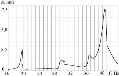
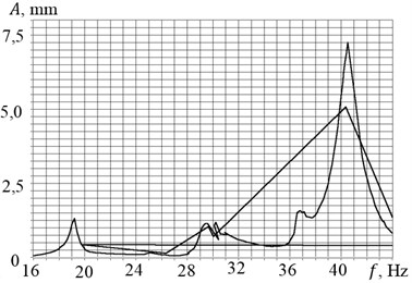
Fig. 3 shows the AFC built in measuring vertical oscillations by the accelerometer No. 1 under monotonic increase in (a) and reducing (b) frequency of rotation of unbalanced masses. Fig. 4 – AFC, built in the measurement of the horizontal oscillations by the accelerometer No. 3. Similar results were obtained when measuring the vertical vibration by the accelerometer No. 2. The AFC shows that in the investigated range there are three resonant frequencies: 19.5 Hz, 30.5 Hz and 40.5 Hz. Moreover, during speeding-up there is an obvious breakdown of the amplitudes of the oscillations after the passage of the resonant frequencies. Note that when starting and stopping the amplitude of resonance oscillations are significantly different, and the resonance frequencies remain almost unchanged (see Table 1).
Fig. 3AFC under the 1st accelerometer measurements when a) the acceleration and b) rundown
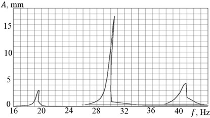
a)
b)
Table 1The resonant frequency and amplitudes of vibrations
Accelerometer No. 1 | Accelerometer No. 2 | Accelerometer No. 3 | ||||||||
Resonant frequency , Hz | Speeding-up | 19.6 | 30.6 | 40.83 | 19.61 | 30.5 | 40.61 | 19.5 | 29.6 | 40.6 |
Rundown | 19.2 | 29.62 | 40.5 | 19.2 | 29.6 | 40.5 | 19.2 | 29.5 | 40.5 | |
Oscillations amplitude , mm | Speeding-up | 3.0 | 16.5 | 4.3 | 2.6 | 15.5 | 3.7 | 2.6 | 1.2 | 7.65 |
Rundown | 1.6 | 7.28 | 3.75 | 1.3 | 6.4 | 3.62 | 1.3 | 1.15 | 7.25 | |
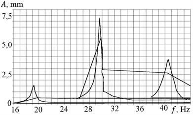
Accelerometer No. 3, installed in a horizontal direction, shows a very small amplitude at the second resonance frequency, indicating a predominantly vertical vibrations of the installation at this frequency (Fig. 4). A small peak at a frequency of about 37 Hz before the third resonant frequency indicates one more degree of freedom. Additional observation of the system behavior in the stroboscopic illumination showed the excitement of angular oscillations of the setup at this frequency in a horizontal plane about a vertical axis (not captured by vertically oriented accelerometers No. 1 and No. 2), indicating a non-ideal centering of the installation and the appearance of gyroscopic moments during rotation of the unbalanced masses.
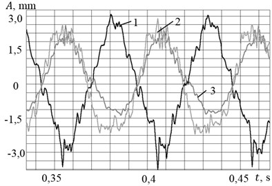
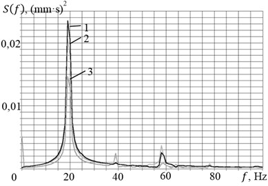
The obtained features of the experimental frequency response are associated with the nonlinearity of the system, caused by interaction with the engines of limited power. Parasitic lines in Fig. 3(b) and 4(b) appeared due to the fact that the measurement system had also registered the fluctuations of the installation with the rapid speeding-up to 3000 rpm. To determine the mode shapes at resonant frequencies we conducted a comparative analysis of the time signals measured by vertically oriented accelerometers. Here are the oscillogram (Fig. 5(a)) and spectral characteristics (Fig. 5(b)) of the signals of each of the accelerometers at a rotation frequency of 19.5 Hz (curves 1 and 2 correspond to the signals from the vertically oriented accelerometers, and curve 3 – a horizontally oriented accelerometer).
Fig. 4AFC when measuring by the 3-d accelerometer a) at speeding-up and b) rundown
a)
b)
Fig. 5a) Oscillogram of displacements and b) spectral density of the signals at an excitation frequency of 19.5 Hz
a)
b)
It is seen that in the points where the accelerometers No. 1 and No. 2 are installed, the vertical oscillations of the platform happen with almost the same amplitudes (curves 1 and 2 in Fig. 5(a), but in opposite phase. This characterizes the excitation of angular oscillations of the platform. All the signals appear to be polyharmonic processes with base frequency of 19.5 Hz and additional higher harmonics with a frequency of 39 Hz 58.5 Hz and 78 Hz, which also indicates the nonlinearity of the system.
Similar results were obtained in the analysis of vibrations at other resonant frequencies. At the frequency of the second resonance (30.5 Hz) the signals from the vertically oriented accelerometers were in phase. In that case the amplitudes of vertical oscillations greatly exceeded the amplitudes of the horizontal oscillations. This characterizes the excitation of the vertical unidirectional oscillations of the platform. Non-zero data from piezo accelerometer No. 3 with a horizontal axis of sensitivity (see Fig. 4) at this frequency are connected mainly with the existence of cross sensitivity (up to 7 % of the sensitivity in the main direction). Analysis of the oscillogram for a third excitation frequency (40.5 Hz) showed that the system implements a form of horizontal oscillations, since their amplitudes (green) significantly exceed the amplitudes of the vertical oscillations.
Simultaneously with the determination of the resonance forms and frequencies of oscillations of the platform, we measured the rotation speeds of the unbalanced masses and their phase displacements using both the signals from the encoders and the stroboscopic lighting. Note that, from the frequency of approximately 16 Hz and above, we saw almost complete synchronization of the speeds of the unbalanced masses rotation, and also their phase displacement was determined by the form of oscillations of the platform. At the frequency of the first and third resonances (angular and horizontal oscillations modes) phase displacement was 180°, and at the frequency of the second resonance (vertical oscillations mode) – 0°. Instrumental error of the encoders while measuring the relative position of the phases did not exceeded 3 %.
6. Conclusions
Experimental studies of a mechanical system have shown the occurrence of a self-oscillating adaptive self-synchronization of unbalanced masses, the mutual phase displacement of which depends on the oscillations modes of the carrier body. In other words, the change of the frequency of the synchronous antiphase rotation of the unbalanced masses leads to various vibration modes of the carrier body, which, in turn, leads to various mutual phase displacements of the unbalanced masses.
Despite the linearity of the elastic system when the system oscillates, we see evident signs of a nonlinear system, caused by non-ideality of the torque characteristics of the asynchronous motors of the unbalanced vibrators.
References
-
Astashev V., Babitsky V., Vulfson I. Dynamics of Machines and Machine Control. Mechanical Engineering, Moscow, 1988, (in Russian).
-
Blekhman I. I. Vibrational Mechanics. Nauka, Moscow, 1994, (in Russian).
-
Nagaev R., Guzev V. Self-Synchronization Inertial Vibration Exciters. Mechanical Engineering. Leningrad, 1990, (in Russian).
-
Vibration in the Technique: Handbook. In 6 Vols. V.4. Vibration Processes and Machines. Mechanical Engineering, Moscow, 1981, (in Russian).
About this article
The study was performed account for a grant the Russian Science Foundation (Project No. 15-19-30026).
