Abstract
On the base of the carried out measurement in 2013 and 2014, the stationary measurement system has been developed for vibrodiagnostics of railway vehicles. This system is currently in a trial operation in Prague's subway. The principle of the railway vehicle bogie diagnostics is based on noise and vibration measurement of a railway superstructure. The measurement system is self-contained – it saves the measured data of a passed train automatically, including identification of the trainset and the each wheelset. The measured data are evaluated in the frequency domain, where failure symptoms are identified. The measurement repeatability makes possible application of a neural network for detection of the failure symptoms. The next phase of this project will concern to the application of the neural network. The function of the developed device and the principle of failure detection are described in this paper. The existing results of the carried out measurement are presented too.
1. Introduction
This paper continues the article of title “Diagnostics of Railway Vehicle Based on Dynamical Response Measurement“ published in last Vibroengineering Procedia [1], where the system of railway vehicle diagnostic measurement based on sensors located in track was described. The evaluation of that measurement showed that the designed system is suitable for diagnostics of vehicle bogie parts. Based on these positive results, the new and completely autonomous measuring system has been developed. This new system contains optimized location and number of sensors, it is also prepared for installation at the selected track section without limitation of distance from the station and it allows automatic data recording. This paper is concerned to description of optimized diagnostic system and method of measured data evaluation.
2. Location of sensors in measuring track section
In 2014 the new diagnostic measuring system was in testing operation at track sections of line A and line C of Prague underground system.
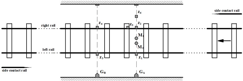
At line A, all sensors (accelerometers, microphones and optical gates) were located in the transient part of the track situated about 100 m from the “Malostranská” station in direction of end station “Nemocnice Motol” (see Fig. 1). At line C, the sensors were located in the straight track situated about 30 m from the “Opatov” station in direction of end station “Háje”. The measuring track section at line C is specific in side contact rail interruption and changing to the other side of the track (see Fig. 2).
In a measuring track section, two pairs of accelerometers , and , were situated on the foot of rail between sleepers in the same track cross-section as two optical gates , . Accelerometer was situated also on the foot of rail but above sleeper and accelerometer was placed on the concrete bed beside a track in the same track cross-section as the accelerometers and . Two microphones and are situated between sleepers close to each other.
The evaluation method doesn’t utilize all sensors; some of them are used for verification or as a reserve.
Fig. 1Location of accelerometers, microphones and optical gates in measuring track section of line A
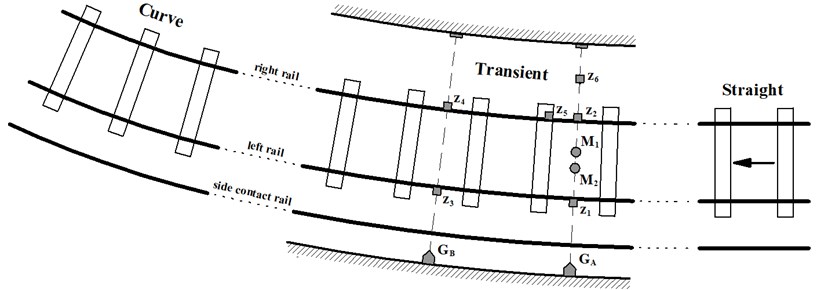
Fig. 2Location of accelerometers, microphones and optical gates in measuring track section of line C
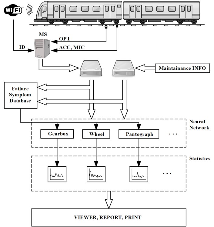
3. Autonomous diagnostic measuring system
Diagnostic measuring system is designed for the automatic data recording during trainset passing over the measuring track section. Above that, it can be located to any underground track section independently of the station distance. Fig. 3 describes the method of data collection and its evaluation.
Container with measuring computer is situated near the measuring track section and it is connected to any external computer by optical cable. With help of remote desktop an external computer is used for monitoring of measuring process and setting appropriate parameters of measurement. Because the system utilizes the optical gates for starting and stopping measuring set, there is no requirement for any attendant during operation. However due to using of high sampling rate of recorded data (50 kHz), it is necessary to remove recorded data in suitable period to storage and carry out next process. Data removing and processing is performed in the night operation lockout. Due to a considerable amount of measured data (about 4000 data sets per month), the process has to be also automatic.
For each measured train passing, the identification number of the vehicle is assigned with help of WiFi. By this unique number of each vehicle can be identified during data evaluation process.
In terms of diagnostics, the knowledge about actual technical state of a vehicle or its parts is necessary during the data evaluation process. Therefore the measured data are complemented by necessary information obtained from the maintenance interventions and the periodical inspections.
A database of possible failure symptoms is the next information source. This database is created on the base of carried out measurement of passing vehicles with known failures.
4. Using of diagnostics in operation – vehicle failures analysis
The designed diagnostic measuring system is suitable only for detection of failures which can create a response in measured acceleration on rail or in vehicle external noise. In this context, we can detect these typical failures:
– failures of axle gearbox (vibration),
– wheel tread failures (vibration, with limitation),
– incorrect side pantograph force (noise, measuring near the beginning of side contact rail),
– axle bearing failures (noise, vibration),
– unbalanced rotor of traction motor (noise, vibration).
For the correct failure detection, there is necessary to know exact time of each axle passing, vehicle speed and acceleration. Time of axle passing is determined by optical gates; values of each axle speed and acceleration of the whole trainset are calculated. This method enables detection of failure symptoms for corresponding axles (transmissions, wheel treads, axle bearings, traction motors) or for corresponding center of bogies (side pantographs). Failure symptoms are detected in time, when their response is expected (impact of a side pantograph on a side contact rail). This time is calculated with help of speed and time of last axle detection by optical gate, because the ramp of the side contact rail may not be directly in measuring track section (in case of line C testing measurement, the ramp of the side contact rail was in distance 3.8 m from the measuring track section).
After determination of time interval when a failure symptom is expected, FFT spectrum is calculated in suitable time window. This FFT spectrum is base for evaluation.
Fig. 3Autonomous diagnostic measuring system and principle of data evaluation
5. Measurement results and its utilization for various methods of evaluation
The basic presumption for objective data evaluation is repeatability of measurement. In that term the underground system operation is suitable for testing of this diagnostic measuring system, because each trainset passes over the measuring track section several times in one day. For example, Fig. 4 represents FFT spectrum of 14th axle of trainset No. 115 for 8 passing in one day. The speed of the axle was in the range from 17.1 to 17.5 ms-1. For high variance of speed it is not possible to ensure the repeatability however, in our case, the speed variance of all passing was low enough.
Fig. 4Measurement repeatability (FFT spectrum) – trainset No. 115, axle No. 14, 8 passing
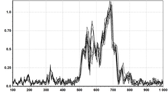
Fig. 5Spectrogram of acceleration signal of sensor z4; passing No. 120026 of trainset No. 115 (frequency range 100-1000 Hz) – response of axle gearbox (A) and rails contact (B)
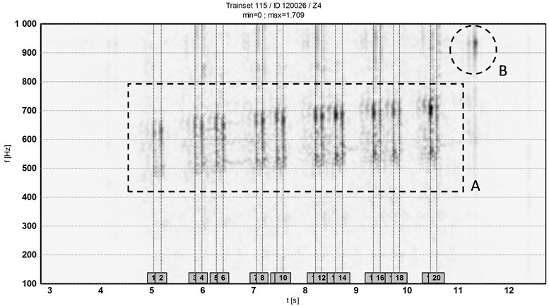
A spectrogram of whole trainset passing calculated from signal of sensor is presented in Fig. 5. Area A contains responses of axle gearboxes. Area B shows response of passing of the last bogie over contact of two rails (isolated contact), which is situated in distance 13.2 m from the measuring track section. The vertical lines represent calculated time of passing of axles.
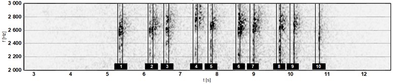
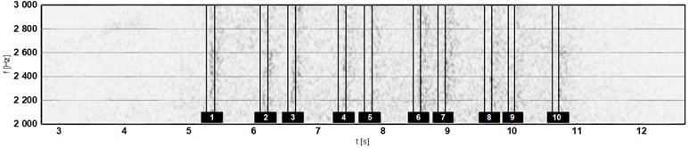
Spectrograms of noise measured by microphone are shown in Fig. 6. The response of side pantograph with high initial force is seen in the upper spectrogram, the response of side pantograph with low initial force is seen in the lower spectrogram. It is also possible to estimate adjusted height of the side pantograph (distance between vertical lines corresponds with height of ramp of side contact rail). Side pantograph of the 1st bogie is adjusted to higher position than side pantograph of 9th bogie.
Fig. 6Spectrogram of noise signal of microphone M1; passing No. 120026 of trainset No. 115 (frequency range 2000-3000 Hz): a) response of side pantograph with high initial force and b) with low initial force
a)
b)
6. Evaluation by neural network implementation
The special software system has been developed to evaluation of measurement results with help of neural network. In the future, it will be expanded to detection appropriate failures. The first test were carried out by this system – it has been learned to responses of some trainsets and next it should recognize the learned signal (trainset) from the package of all passing (trainsets).
From the FFT spectrum, the frequency range of 0-3 kHz has been used as input. Input data for neural network contains 512 elements. Neural network consists of one input layer, two hidden layers and output layer of one element. A value in the range of 0-1 is the output of the neural network; value “1” represents recognizing of searched signal (trainset). The package of trainset passing with passing rate of 10 has been chosen. Then the neural network has been learned to this trainset passing and a test has been carried out over all passing and by this process, the functionality was verified.
Table 1Neural network output – trainset finding
101 | 102 | 106 | 108 | 109 | 111 | 113 | 115 | 116 | 119 | 124 | 126 | 129 | 131 | 133 | 135 | 139 | 140 | |
111 | 0.00 | 0.00 | 0.00 | 0.00 | 0.00 | 1.00 | 0.00 | 0.00 | 0.00 | 0.00 | 0.04 | 0.00 | 0.00 | 0.00 | 0.00 | 0.00 | 0.05 | 0.00 |
115 | 0.01 | 0.00 | 0.10 | 0.00 | 0.00 | 0.06 | 0.01 | 0.99 | 0.01 | 0.03 | 0.09 | 0.00 | 0.00 | 0.00 | 0.04 | 0.01 | 0.06 | 0.01 |
119 | 0.01 | 0.00 | 0.03 | 0.00 | 0.00 | 0.00 | 0.01 | 0.00 | 0.02 | 0.94 | 0.00 | 0.01 | 0.01 | 0.00 | 0.00 | 0.01 | 0.01 | 0.01 |
124 | 0.00 | 0.00 | 0.00 | 0.00 | 0.00 | 0.06 | 0.00 | 0.06 | 0.00 | 0.01 | 1.00 | 0.00 | 0.00 | 0.00 | 0.05 | 0.00 | 0.07 | 0.00 |
7. Conclusion
The measurement results shows, that the data have a satisfied repeatability for the same trainsets, but there are differences between different trainsets. This fact enables the recognizing of trainsets with help of neural network. Actually the next phase of our research in this area is taking place, which is concerned to implementation of the neural network to the failure evaluation method. For the determination failure development process, the measurement has to be carried out in time period – now it is possible due to autonomy of measuring system. Obtaining of data of failure trainset passing is the next important step, which can be carried out after implementation of the measuring system to the testing operation and import of all operational and service data.
References
-
Hába A., Zelenka J., Musil M., Vágner J., Kohout M., Havlíček P. Diagnostics of railway vehicle based on dynamical response measurement. Vibroengineering Procedia, Vol. 3, 2014, p. 272-277.
-
Zelenka J., Musil M., Kohout M., Hába A., Michálek T., Havlíček P. Implementation of a Device for Indication of Failure States of Running Vehicles in Metro Operation. Technical Report No. CKDV-WP14-2013-MM-01, University of Pardubice, 2013.
-
Kreidl M. Diagnostic Systems. First edition, ČVUT, Prague, 2006.
-
Bíla J. Factitious Intelligence and Neural Networks in Application. Second Edition (Revised), ČVUT, Prague, 1998.
About this article
This paper was supported by Technological Agency of Czech Republic within the Project No. TE 01020038.
