Abstract
A dynamic analysis model is established for a train-bridge system subjected to a vessel collision-load. A (32+48+32) m continuous bridge with PC box girders and a CRH2 high-speed train are considered as a case study. The whole histories of the train running on the bridge are simulated while the vessel collision load acting on the pier, based on which the dynamic responses of the bridge and the running safety indices of the train on the bridge are evaluated. The results show that the dynamic responses of the bridge are greatly increased by the vessel collision load, resulting in a big influence on the running safety of high-speed train.
1. Introduction
With the development of transportation, more bridges crossing navigable rivers have been constructed. At the same time, the tonnage of vessels grows heavier and the speed becomes faster. Consequently, the accidents of vessel collision with bridges occur from time to time.
When a collision load acts on a bridge, it may cause deformation and even collapse of girders, resulting in serious accidents [1, 2]. For high-speed railway bridges, even if there is no girder collapse, the vibration and displacement induced by the collision may deform the track, and the running safety of the train may be seriously affected. However, up to the present, only a few published papers [2] concerned the vibration of the train-bridge system induced by a vessel collision and its influence on the running safety of the train, while on this problem it lacks of specialized research. To this end, this paper presents an analysis model, and analyzes the dynamic responses of coupled train-bridge system subjected to a vessel collision.
2. Train-bridge model subjected to a vessel collision load
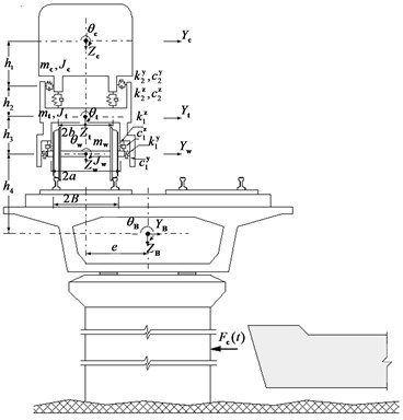
The dynamic analysis model is established by adding the collision load applied on the bridge pier as an external excitation to the train-bridge system model [3], as shown in Fig. 1.
In the model, the bridge is simulated by a finite element model, the train vehicles by multi rigid-bodies with elastic connections, and the wheel-rail relationship is assumed as close contact, without detach during the movement of the wheel on the rail. In the analysis, it is assumed that there is no relative displacement between the track and bridge deck. The track irregularities are taken as the system input that determine the relative displacement between wheel-sets and rails.
The equations of motion for the train-bridge system subjected to a collision load can be expressed as:
where: , , and are the mass, damping and stiffness matrices, with the subscripts “” and “” representing the train and the bridge, respectively; and are, respectively, the displacement vectors of the train subsystem and the bridge subsystem with generalized modal coordinates; and are the inter-force vectors of the bridge and the train vehicle. Details of these matrices and vectors can be found in [3]. is the generalized collision force vector acting on the bridge, which can be expressed as:
where: is the generalized collision force acting on the bridge corresponding to the th mode. Suppose the collision forces act horizontally on the pier, can be expressed as:
where: is the fuction value of the th mode shape in horizontal direction; is the total number of bridge nodes; is the collision force history of truck on the bridge at the th node, which is only different from zero at the pier nodes affected by the collision.
When the train runs on the bridge, the acting positions of the inter-forces between the bridge and the train vehicles are always varying, which makes Eq. (3) become a second-order linear non-homogeneous differential equations with time-varying coefficients. In this study, these equations are solved using the Newmark implicit step-by-step integration algorithm with 1/4. Details of the solution can be found in [3].
Fig. 1Dynamic model for train-bridge system subjected to vessel collision
3. Dynamic analysis of a train-bridge system subjected to vessel collision
3.1. Bridge description and calculation parameters
A bridge situated on the Herbin-Dalian high-speed railway in Northeast China is taken as an illustrative case study. The bridge is composed of (32+48+32) m continuous PC girders with box sections. A 32 m double-track simply-supported girder is added at each end of the continuous spans, as shown in Fig. 2.
For the continuous girder, the widths of top slab and bottom plate are 13.4 m and 5.74 m respectively, and the depth is 3.0 m for the whole span length. The secondary phase dead-load applied on the bridge model is 18.5 t/m.
The bridge adopts concrete solid piers with round-ended sections and pile foundations. The two middle piers are 19.45 m high and two side piers 10.0 m. For the (32+48+32) m continuous spans, mounted on the Pier 2 are fixed bearings, while the rest are movable ones.
The high-speed train CRH2 used in China is adopted, composed of (3+1)×3 cars, with representing the motor-car and the trailer-car, respectively. The average axle loads are 132.44 kN for the motor car and 117.72 kN for the trailer-car. The parameters of the train vehicles can be found in [3].
The track on the bridge is a ballastless PC slab track. The track vertical, lateral and rotational irregularities are taken into consideration by using the data measured in the Qinhuangdao-Shenyang High-speed Railway in China [3].
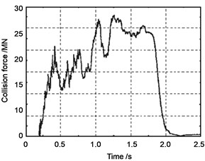
In the analysis, the time history of collision load given in reference [4] is used as the external load input to the train-bridge system model, as shown in Fig. 3.
Fig. 2Configuration of the (32+48+32) m continuous bridge with 32 m side spans
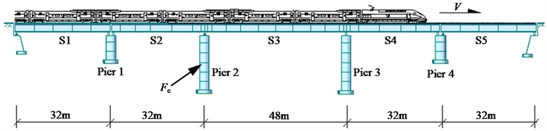
Fig. 3Impact force time history of a vessel on concrete pier (impact velocity V= 4.0 m/s)
By a FEM analysis, the free vibration characteristics including frequencies and mode shapes of the bridge are obtained, and the first 30 modes are used in the calculation. The damping ratio of the bridge structure is taken as 2.5 %, and the integration time step is taken as 0.0001 s.
3.2. Dynamic responses of train-bridge system
With the above bridge, train and track irregularity parameters, the whole histories of the train travelling on the bridge are simulated, in which two cases with and without vessel collision on the bridge pier are considered. In the case with collision, the force time history of Fig. 3 is used as the collision load, but it is normalized as 15 MN to better illustrate the responses of the bridge and the train. In the analysis, collision load is applied on Pier 2 at 10.20 m above the cap of the pier foundation when the train arrives at middle of the second span (S2).
3.2.1. Dynamic responses of the bridge
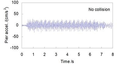
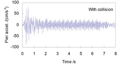
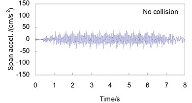
Shown in Figs. 4 and 5 are, respectively, the lateral displacement and acceleration time histories at the top of Pier 2 and at the mid-span of the 48 m span without and with collision load, when the CRH2 train travels on the bridge at 250 km/h.
It can be seen from the figures that the effect of the vessel collision on the lateral bridge responses is obvious, which can be summarized as follows:
In the case without collision, the lateral responses of the bridge are induced by the running train only, therefore the time history curves are steady, with very small amplitudes in both the displacements and the accelerations. For the pier-top and the mid-span, the maximum displacements are 0.061 mm and 0.074 mm, and the maximum accelerations are 31.2 cm/s2 and 38.9 cm/s2, respectively.
While in the case with a vessel collision, the lateral responses of the bridge are greatly amplified. For the displacements, the peak values are 1.72 mm at the pier-top and 1.41 mm at the mid-span, 28.2 and 19.1 times of those without collision. For the accelerations, they are 83.7 cm/s2 at the pier-top and 119 cm/s2 at the mid-span, 2.68 and 3.06 times of those without collision. The time histories of bridge response show significant impact waveform features. Owing to the damping action of the concrete pier and the girder, the shock waves induced by collision last for a very short time, and both the displacement and the acceleration curves return very soon to their steady state as the case without collision after the collision load is finished.
Fig. 4Lateral displacement histories of the bridge (V= 250 km/h)
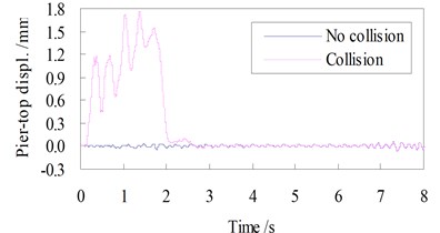
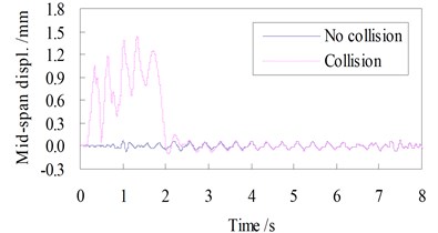
Fig. 5Lateral acceleration histories of the bridge (V= 250 km/h)
3.2.2. Dynamic responses of the train vehicles
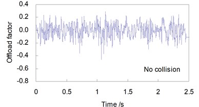
The evaluation indices and the corresponding allowances for the running safety of the train currently adopted in the high-speed railways in China include: the derailment factor 0.8, and the offload factor 0.6 [3].
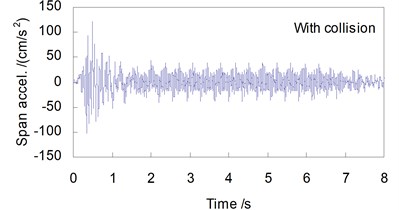
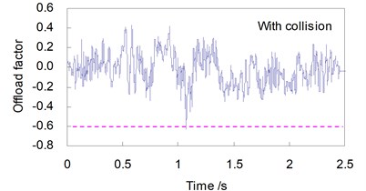
Shown in Figs. 6 and 7 are, respectively, the time histories of and of the first wheel-set of the train in two cases without and with a vessel collision, when the train travels on the bridge at a speed 250 km/h.
Obvious differences can be found between the time histories of running safety indices when the CRH2 train travels on the bridge without and subjected to a vessel collision load.
There appear strong shock waveforms in the time history curves of derailment factors and offload factors when the collision load acts on the bridge. The maximum values for the running safety indices induced by the vessel collision force of 15 MN and the train speed 250 km/h are greatly amplified: increased from 0.458 to 0.971 by 112 %, and from 0.324 to 0.628 by 93.8 %, both exceeding the related allowances in the code.
Fig. 6Derailment factor curves of the train (V= 250 km/h)
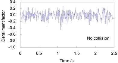
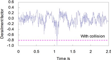
Fig. 7Offload factor curves of the train (V= 250 km/h)
4. Influence of vessel collision with bridge on running safety of train
In this section, with the same bridge, train and track irregularity parameters, the effect of a vessel collision with the bridge pier on the running safety of train is investigated by considering different collision force intensities and train speeds. The maximum values of running safety indices, which are taken from the corresponding time histories of all wheel-sets during each passage of the train on the bridge, are used for comparison and are evaluated with the safety evaluation indices.
While keeping the parameters of the bridge and the CRH2 train unchanged, the train speed is varied from 160 km/h to 320 km/h, and three loading cases are considered: no collision, vessel collision loads in Fig. 3 with their intensities normalized as 10 MN and 15 MN, respectively. The distributions of the maximum and versus train speed are shown in Fig. 8, in which the horizontal dashed lines represent the related allowance values.
Fig. 8Distributions of running safety indices vs train speed
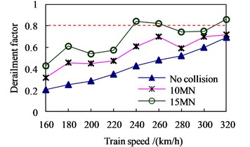
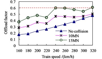
Generally, the higher the train speed, the bigger the running indices. Without collision and with collision 10 MN, all the running indices can meet the allowances, and the train can run on the bridge safely up to 320 km/h. While for the collision 15 MN, and exceeded the related allowances of 0.8 and 0.6, respectively, at 240 km/h.
Keeping unchanged the shape and durations of the collision load, the influence of collision intensity on the running safety indices is analyzed by changing the collision intensities from 0 MN to 20 MN. Two train speeds, 200 km/h and 250 km/h, are considered. The distributions of and versus collision intensities are shown in Fig. 9.
Fig. 9Distributions of running safety indices vs collision intensity
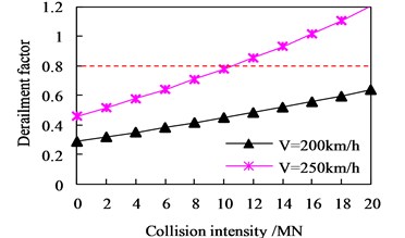
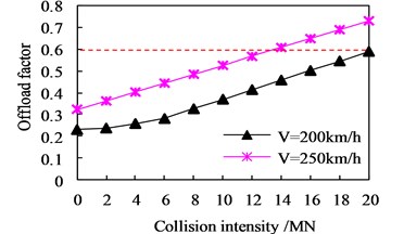
The results show that the derailment factors and offload factors increase with the collision intensity. At the train speed 200 km/h, the running safety of the train can be ensured for the collision up to 20 MN. At the speed of 250 km/h, exceeds the allowance when the collision is 12 MN, and with further increase of collision intensity, exceeds the related allowances when the collision reaches 14 MN and 18 MN, respectively.
5. Conclusions
1) Collision load has obvious effect on the dynamic responses of the bridge and the running train. The lateral displacement and acceleration responses of the bridge subjected to vessel collision are much greater than those in the case without collision, exerting a great influence on the running safety of high-speed train. This effect should be fully recognized in design of high-speed railway bridges.
2) Strong collision may threaten the running safety of high-speed train, which is affected by both the collision intensity and the train speed. Generally, the greater the collision intensity, the lower the safety train speed, while the higher the train speed, the smaller the collision load that the train-bridge system can allow.
References
-
Derucher K. N. Bridge pile damage upon vessel impact. Computers and Structures, Vol. 18, Issue 5, 1984, p. 931-935.
-
Laigaard J. J., Svensson E., Ennemark E. Ship-induced derailment on a railway bridge. Structural Engineeirng International, Vol. 6, Issue 2, 1996, p. 107-112.
-
Xia H., De Roeck G., Goicolea J. M. Bridge Vibration and Controls: New Research. Nova Science Publishers, New York, 2011.
-
Chen C. Design Collision Loads and Simulation of Damage for Bridge Piers Subjected to Ship Impact. Master’s Dissertation, Tongji University, Shanghai, China, 2006.
About this article
This research is supported by the Natural Science Foundation (Grant No. 51308035) and the Fundamental Research Funds for the Central Universities of China (Grant No. 2015RC006).
