Abstract
There are three types of waves propagating in the saturated soils, which are fast pressure waves (P1 waves for short), slow pressure waves (P2 waves for short) and shear waves (S waves for short), and their wave numbers are firstly given in this paper. The lengths of elastic piles are much larger than the diameters in order to obtain ideal isolation effectiveness, so the isolation of SV waves by discontinuous barriers composed of several rows of piles can be simplified as a 2-dimensional plane problem. The conformal mapping method of complex functions and expansion method of wave functions are adopted, the incident, scattered and refracted waves are all expanded to the special functions with infinite series, the stresses and displacements are considered as continuous at the boundaries between the piles and adjacent saturated soils, and finally the theoretical solutions about the complex coefficients of the expanded potential functions are obtained. The normalized vertical displacement amplitudes are introduced, which are the ratios of displacement amplitudes of saturated soils caused by both the incident and scattered waves to those only by the incident SV waves, the isolation effectiveness of the barriers composed of one, two and three rows of piles are compared, and the factors that influence the isolation effectiveness are analyzed, which provides some references on the vibration isolation design.
1. Introduction
Man-made vibrations such as pile driving construction, railway and highway traffic vehicles, heavy industry and engineering explosion are becoming more and more frequent, and they have caused adverse influences on precise instrument processing and human’s life. In general, the previous approaches used to reduce the ground vibration strength near the man-made vibration sources can be categorized as the active and passive approaches. The active isolation measures are commonly used to isolate the vibration source from the ground; therefore, they are usually arranged around the vibration source in a very close distance. On the other hand, the passive isolation measures are normally used to reduce the energy transmitted to the protected structures, and consequently, they are usually arranged surrounding protected structures. Continuous and discontinuous barriers are the most two types of passive measures: open or in-filled trenches, and one row or several rows of piles or cylindrical cavities. Among these, discontinuous barriers are the advantageous barriers for the fields with higher groundwater level.
Continuous barriers such as open and in-filled trenches have been studied in the recent thirty years [1-8], and the relative results all reveal that ideal vibration isolation effectiveness can be obtained from a deeper open trench while the trench width has less influence on the vibration isolation effectiveness. But as to man-made vibrations with low frequencies, an open trench should be constructed too deep to obtain better vibration isolation effectiveness, and so to maintain the stability of the four sides of the trench is much important for guaranteeing the isolation effectiveness in the future. In order to reduce the maintenance fees of open trenches and obtain the appropriate vibration isolation effectiveness, discontinuous barriers composed of a row of piles and cylindrical cavities are designed to replace the open trenches where the soils are not suitable for excavations and maintenance such as soft soils with higher water tables.
Nowadays some geotechnical engineers are interested in discontinuous barriers especially those composed of a row of solid or pipe piles [9-18], and some important conclusions have been drawn out: the shear modulus of the piles, the spacing distances between the piles and the wall thickness of the pipe piles are the main factors that influence the isolation effectiveness.
From the above-mentioned studies we can find that, open trenches have better vibration isolation effectiveness but their applications are limited to the excavation depth, while one row or several rows of piles have less isolation effectiveness than open trenches but they are not limited to the depth and can be applied in all soils.
The soft soils with higher water table can be studied as saturated soils, and there are three types of waves propagating in the saturated soils, which are fast pressure waves (P1 waves for short), slow pressure waves (P2 waves for short) and shear waves (S waves for short) [19], while there are only two types of waves in elastic media, which are pressure waves (P waves for short) and shear waves (S waves for short). In this paper, the SV waves that cause the vertical vibration of the ground are taken as example, the isolation of SV waves by several rows of piles in saturated soils is studied, and the factors that influence the isolation effectiveness are analyzed.
2. Wave functions of the saturated soils
According to Biot’s wave theory [19], the control equations in saturated soils are mainly include 4 equations as follows:
1) Stress-strain relationships:
2) Seepage equation of continuity:
3) Motion equation regardless the body forces:
4) Fluid motion equation:
where, , , , is the pore water pressure, and are the Lamé elastic constants of the solid skeleton, is the displacement of solid skeleton, is the displacement of water compared to the solid skeleton, and are two compaction coefficients that reveal the soil particles and pore water, is Kronecker Delta, is the density of the whole saturated soils, is the density of solid particles, is the density of pore water, is the porosity of the saturated soils, and and are viscous and permeability coefficients of the pore water.
Substituting Eqs. (1) and (2) into Eq. (3), and Eq. (2) to Eq. (4), the vector equations about the saturated soils are obtained:
where, , and and are the two displacement vectors.
Scalar potential functions of and and vector potential functions of and are introduced, and the displacement vectors of and are parted as follows:
Put Eq. (6) into Eq. (5), the wave functions of saturated soils are obtained in the forms of matrix:
where, and is the frequency of incident waves.
The complex wave numbers , and of P1, P2 and S waves can be obtained from Eq. (7):
where, , and .
In the Eq. (6), potential functions of , and are used to denote the potential functions of P1, P2 and S waves propagated in the solid skeletons of the saturated soils, while , and to denote those propagated in the liquids, and these potential functions have the relationships as follows:
where, , and are:
3. Potential functions of waves
3.1. Potential functions of the incident SV waves
The waves generated by traffic loads and other man-made vibrations are mainly propagated in the above 10 meters under the ground surface, which is less than the Rayleigh wave length, while the length of the piles that used to isolate the vibrations are usually larger than 10 meters, so the waves generated by the vibrations can be scattered by the piles in large scale and then reduce the vibrations, and the scattering problem can be simplified as a 2-dimensional plane problem.
P2 waves would be attenuated quickly in the saturated soils and they accounted for the negligible proportion of the total energy of elastic waves, and so incident P2 waves are ignored as for the passive vibration isolation for the protecting structures that are usually far away from the vibration sources. The incident P1 waves or SV waves would be coupling scattered, that is to say that the scattering waves all include P1 waves, P2 waves and SV waves, the studying method and procedures are similar for the incident P1 waves or SV waves, and so the incident SV waves are only considered.
The saturated soils are taken as infinite homogeneous media, and there buried piles whose lengths are much larger than their diameters, so the isolation problem can be simplified as a 2-dimensional plane scattering problem. local Cartesian coordinate systems of are introduced, as shown in Fig. 1. The point is an arbitrary point in the saturated soils.
Fig. 1Distribution of piles and coordinate systems
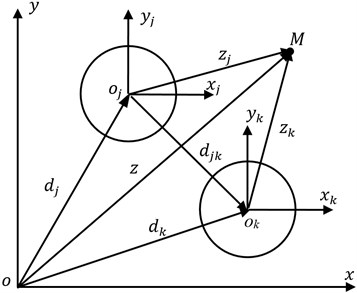
The potential function of incident SV waves with frequency of in the reference Cartesian coordinate systems of can be written as:
where, superscript of “” denotes incident, is the displacement amplitude of incident SV waves, is the angle between incident SV waves and horizontal direction, and is wave number of SV waves in the saturated soils that can be calculated from Eq. (8b). In order to discuss and compute easily, the public time factor of is omitted in Eq. (11) and the lower equations.
According to the relationships of and , Eq. (11) can be represented in the form of reference complex coordinate system :
The complex coordinate system and th local complex coordinate system have the relationship of , so Eq. (1) can be further written as:
3.2. Potential functions of the scattered waves
Similar to Eq. (13), the potential function of scattering P1 waves by th pile that satisfies with the steady-state wave motion and Sommerfeld radiant condition in th local complex coordinate system can be written as:
where, superscript of “” denotes scattering, are the complex coefficients to be determined from the boundary conditions, and is the first kind of Hankel function with order .
The location of observation point can be written in th and th local complex coordinate systems as follows: , , , so Eq. (14) can be written in reference coordinate system and th local complex coordinate system :
The total P1 waves at the observation point that scattered by all the piles are:
And the total scattered P2 waves and SV waves are given directly based on Eq. (16a):
where, and are the complex coefficients to be determined from the boundary conditions.
3.3. Potential functions of the refracted waves in the piles
The piles are taken as infinite homogeneous media, and there are two kinds of waves propagate in them, which are P and S waves. Similar to the piles in elastic soils [20], the potential functions of P and SV waves in the th pile are:
where, superscript of re denotes refracting, - () are the complex coefficients to be determined from the boundary conditions, is the first kind of Bessel function with number of , and are the wave numbers of P and SV waves respectively of the th pile, and the superscript of ~ is adopted to denote the parameters and variables about the piles that can be easily distinguished from those of the saturated soils.
4. Theoretical solutions about the complex coefficients
Conformal mapping equation is introduced: , and stresses, displacements and water pressure in the saturated soils can be calculated from the above-mentioned potential functions:
The stresses and displacements at the boundaries between the piles and adjacent saturated soils are considered as continuous and the piles are water-proof, and the boundary conditions are depicted as:
Put the potential functions of Eqs. (13), (16) and (17) into Eqs. (18) and (19), and the infinite linear equation set about the complex coefficients of - are obtained:
where, , , , and . And the expressions about the matrix elements of - and - are:
where, and .
The coefficients matrix of Eq. (20) is (where, is the effective number of during the calculation), which is not a square matrix and cannot be calculated. To multiply the left and right parts of Eq. (20) with (0, ±1, ±2,…) and make the integral at the interval of at the same time, a square matrix about the coefficient matrix is obtained, and the final theoretical solutions about the complex coefficients of - are as follows:
When calculating Eq. (21), the effective is determined by the receivable error:
where, and are the total displacement in the saturated soils caused by all the P1, P2 and SV waves when the order n is valued and respectively.
5. Numerical results
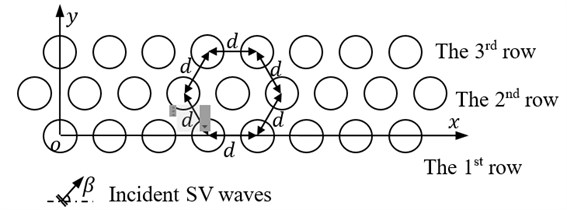
The piles are assumed as uniform with radius of , the spacing distance between the two adjacent piles are all , and the SV waves are assumed to propagate vertically to axis x as shown in Fig. 2, and so .
Fig. 2Arrangement of the barriers composed of three rows of piles
The normalized displacements of is introduced, where is the displacement along axis x caused by both incident and scattered waves behind the barriers, and is the displacement caused by only the incident SV waves. The isolation effectiveness can be evaluated by the value of (1)×100 %, and so is more small and the isolation effectiveness is better.
In order to verify the reasonability of the theoretical methods s adopted in this paper, the theoretical results are compared with FEM, and the vibration isolation model of two rows of piles in elastic soils is selected as an example, as shown in Fig. 3 [11].
Fig. 3Two rows of piles as barrier for vibration isolation
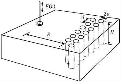
The vibration isolation fields are selected as a cube with each edge of 60.0 m, and the FEM model is built with software of ABAQUS, as shown in Fig. 4. The top of the model is free, the bottom and four sides of the model are defined as absorbing boundaries to avoid the wave reflection and they are divided into 21600 infinite elements, the inner soils are divided into 18000 eight node linear hexahedral elements with each edge of 1.0 m, the two rows of piles are assigned as beam elements with radius 0.2 m and adjacent distance 2.0 m, and the two rows of piles are tied to the soils at the interfaces.
There are some difficulties to reflect the water boundary conditions of the saturated soils with FEM, and so the elastic soils without water are adopted to simulate the vibration isolation problem to verify the reasonability of the theoretical results in this paper. The main physical and mechanical parameters of the elastic soils include elastic modulus 30 MPa, density 1850 kg/m3 and possio’s ratio 0.33, and the ratio of the relative parameters of the piles to saturated soils are 50, 1.35 and 0.75. The distance between the load and piles is 2.0 m, and 17 piles are designed with the first row of 8 and second of 9 as shown in Fig. 2. The load is simplified as a harmonic load , and acts on the top of the FEM model with action area of 1.0 m2. The calculated displacements at the center of 20.0 m behind the two rows of piles are given in Fig. 5.
Fig. 4FEM model built with ABAQUS to simulate the vibration isolation
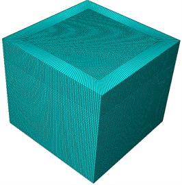
a) Soils and boundaries
b) Piles
Fig. 5Simulated displacements at the center of 20.0 m behind the two rows of piles
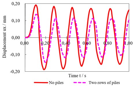
Fig. 6Comparison curves between theoretically calculated and FEM simulated results
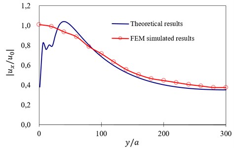
Fig. 5 shows that the maximum simulated displacement at the same place is 0.192 mm with no piles and 0.137 mm with two rows of piles respectively, and so the displacement ratio is 0.715. As to the incident SV waves with frequency of 25, the displacement ratio is 0.680, which is slightly less than the FEM simulated results. And the theoretically calculated curves of at the center of behind the two rows of piles along y axis (0 300) are compared with those simulated with FEM, as shown in Fig. 6.
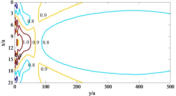
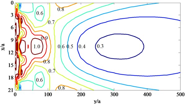
Fig. 7Contours of |ux/u0| behind the barriers with pile row number when ksa= 1.0
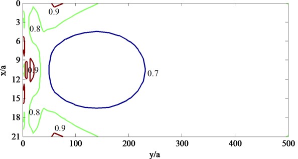
a) One row of piles
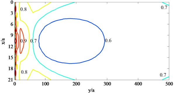
b) Two rows of piles
c) Three rows of piles
Fig. 6 shows that theoretically calculated results are almost near to FEM simulated results especially when is farer that 60.0 with the maximum err of about 6 %, and the theoretical methods in elastic soils are proved to be reasonable, so the similar theoretical methods can be adopted to solve the vibration isolation problems in the saturated soils.
The physical and mechanical parameters are selected based on the silt soils [21] as shown in Table 1.
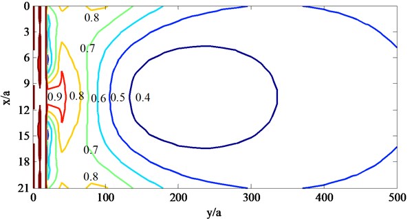
Fig. 8Contours of |ux/u0| behind the barriers with pile row number when ksa= 2.0
a) One row of piles
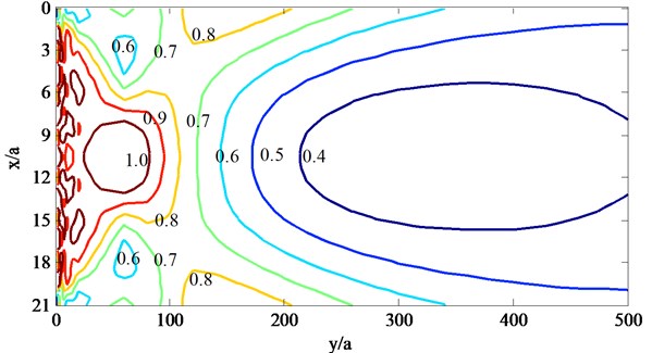
b) Two rows of piles
c) Three rows of piles
The normalized incident frequency is valued 1.0 and 2.0 respectively, the ratio of modulus and density of piles to saturated soils are 50 and 1.35, three kind of arrangements of piles are selected, which are one row (8 piles), two rows (1st row of 8 piles and 2nd row of 9 piles) and three rows (1st row of 8 piles, 2nd row of 9 piles and 3rd row of 8 piles), and contours of in the areas of (021, 0500) behind the barriers are calculated and drawn as shown in Fig. 3 and 8, and the curves of at the position of 10.5 (which is just the center of the barriers) changing with are given as shown in Figs. 9 and 10.
Table 1Physical and mechanical parameters of the saturated soils
/ kg·m-3 | / kg·m-3 | / MPa | |
0.3 | 2650 | 1000 | 11.5 |
/ Pa·s | / MPa | / m2 | |
1.0 | 1×10⁻³ | 6.67×10³ | 1×10⁻⁵ |
Fig. 9Curves of |ux/u0| at the center of the barriers when ksa= 1.0
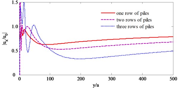
Fig. 10Curves of |ux/u0| at the center of the barriers when ksa= 2.0
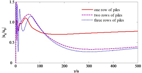
Fig. 7 and 8 show that: (1) the barriers compared of several rows of piles have better isolation effectiveness for higher incident frequencies such as 2.0 than lower incident frequencies such as 1.0, this is because that the incident waves with larger frequencies would be scattered and refracted by the piles more than those with lower frequencies, and so the incident waves would be consumed in large degree; (2) as to the incident SV waves with different frequencies, the displacements would be magnified by the piles and are larger than 1.0 at some locations near the barriers, and this phenomena would be obvious for the barriers with three rows of piles, which is caused by back and forth multiple scattering; (3) as to the incident SV waves with different frequencies and all barriers composed of different rows of piles, the center of the barriers have better isolation effectiveness than the two sides, this is because that the incident waves would diffract from the two sides of the barriers; (4) as to the incident SV waves with different frequencies, the isolation effectiveness increase with the row number of piles.
Fig. 9 and 10 also show that, the row number of piles have different influence on the isolation effectiveness for different incident SV waves, as to the lower incident frequencies such as 1.0, the isolation effectiveness increases with the row number of piles increase from one to three, while as to the larger incident frequencies such as 2.0, the isolation effectiveness increases obviously when row number of piles increase from one to two and not obviously when row number of piles increase from two to three, and this is because that the incident with higher frequencies have shorter wavelengths and would be scattered by the piles intensely.
Take two rows of piles (1st row of 8 piles and 2nd row of 9 piles) as example. The modulus ratio is valued 10, 50, 100 and 500 respectively, other parameters are same to Figs. 7-10, and the curves of at the position of 10.5 of the barriers changing with are given as shown in Figs. 11 and 12.
Fig. 11Curves of |ux/u0| with different modulus ratio when ksa= 1.0
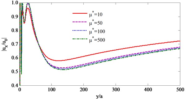
Fig. 12Curves of |ux/u0| with different modulus ratio when ksa= 2.0
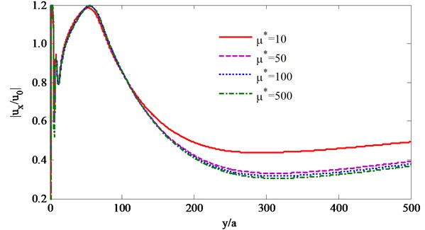
Figs. 11 and 12 show that as to the incident SV waves with different frequencies, the has the similar influence on the isolation effectiveness: the isolation effectiveness increases obviously when increases from 10 to 50 while not obvious when increases from 50 to 500, and so 50 is a better selection based on both isolation effectiveness and construction costs.
6. Conclusions
The conformal mapping method of complex functions and expansion method of wave functions are adopted, the theoretical solutions about several rows of piles as barriers for incident SV waves in the saturated soils are obtained, and some conclusions are drawn out as follows:
1) The barriers composed of several rows piles are better for incident SV waves with higher frequencies than those with lower frequencies.
2) The pile number has different influence on the isolation effectiveness for the incident SV waves with different frequencies: as to incident SV waves with lower and higher frequencies, 3 and 2 rows of piles are the best selection respectively;
3) The stiffness of the piles has similar influence on the isolation effectiveness, and piles with modulus ratio of 50 is a better selection based on both isolation effectiveness and construction costs.
References
-
Woods R. D. Screening of surface waves in soils. Journal of the Soil Mechanics and Foundations Division, Vol. 94, Issue 4, 1968, p. 951-979.
-
May T. W., Bolt B. A. The effectiveness of trenches in reducing seismic motion. Journal of Earthquake Engineering and Structural Dynamics, Vol. 10, 1982, p. 195-210.
-
Emad K., Manolis G. D. Shallow trenches and propagation of surface waves. Journal of Engineering Mechanics, Vol. 111, Issue 2, 1985, p. 279-282.
-
Beskos D. E., Dasgupta B., Vardoulakis I. G. Vibration isolation using open or filled trenches, part 1: 2-D homogeneous soil. Computational Mechanics, Vol. 1, Issue 1, 1986, p. 43-63.
-
Al-Hussaini T. M., Ahmad S. Design of waves barriers for prediction of horizontal ground vibration. Journal of Geotechnical Engineering, Vol. 117, Issue 4, 1991, p. 616-636.
-
Ahmad S., Al-Hussain T. M. Simplified design for vibration screening by open and in-filled trenches. Journal of Geotechnical Engineering, Vol. 117, Issue 7, 1991, p. 67-88.
-
Ahmad S., Al-Hussaini T. M., Fishman K. L. Investigation on active isolation of machine foundations by open trenches. Journal of Geotechnical Engineering, Vol. 122, 1996, p. 454-461.
-
Klein R., Antes H., Le Houédec D. L. Efficient 3D modelling of vibration isolation by open trenches. Computers and Structures, Vol. 4, 1997, p. 809-817.
-
Liao S., Sangrey D. A. Use of piles as isolation barriers. Journal of the Geotechnical Engineering Division, Vol. 104, Issue 9, 1978, p. 1139-1152.
-
Avilés J., Sánchez-Sesma F. Piles as barriers for elastic waves. Journal of Geotechnical Engineering, Vol. 119, Issue 9, 1983, p. 1133-1146.
-
Avilés J., Sánchez-Sesma F. Foundation isolation from vibrations using piles and barriers. Journal of Geotechnical Engineering, Vol. 114, Issue 11, 1988, p. 1854-1870.
-
Boroomand B., Kaynia A. M. Vibration isolation by an array of piles. First International Conference on Soil Dynamics and Earthquake Engineering, Karlsruhe, Germany, 1992, p. 683-691.
-
Yang Y. B, Hung H. H. Parametric study of waves barriers for reduction of train-induced vibrations. International Journal for Numerical Methods in Engineering, Vol. 40, Issue 20, 1997, p. 3729-3747.
-
Kattis S. E., Polyzos D., Beskos D. E. Modelling of pile waves barriers by effective trenches and their screening effectiveness. Soil Dynamics and Earthquake Engineering, Vol. 18, Issue 1, 1999, p. 1-10.
-
Kattis S. E., Polyzos D., Beskos D. E. Vibration isolation by a row of piles using a 3-D frequency domain BEM. International Journal for Numerical Methods in Engineering, Vol. 46, Issue 5, 1999, p. 713-728.
-
Xu P., Zhou X. M., Xia T. D. Discontinuous barrier used a row of elastic piles for incident elastic waves. Journal of Vibration Engineering, Vol. 20, Issue 4, 2007, p. 388-395, (in Chinese).
-
Xu P., Xia T. D., Zhou X. M. Study on effect of barrier of a row of hollow pipe piles on isolation of incident plane SV waves. Chinese Journal of Geotechnical Engineering, Vol. 29, Issue 1, 2007, p. 131-136, (in Chinese).
-
Xu P., Xia T. D., Wu M. Study on the effect of barrier of a row of rigid hollow pipe piles for the isolation of P and SV waves. Engineering Mechanics, Vol. 25, Issue 5, 2008, p. 210-217, (in Chinese).
-
Biot M A. Mechanics of propagation of elastic waves in a fluid-saturated porous solid. The Journal of the Acoustical Society of America, Vol. 28, Issue 2, 1956, p. 168-191.
-
Pao Y. H., Mow C. C. Diffraction of Elastic Waves and Dynamic Stress Concentrations. Crane, Russak and Company Inc., New York, 1973.
-
Wu S. M. Wave Propagation in Soils. Science Press, Beijing, 1997, (in Chinese).
About this article
This work is supported by the National Natural Science Foundation of China (Grant Nos. 51008286, 51278467), National Natural Science Foundation of China (Grant No. 2015M582204), Program for Science and Technology Innovation Talents in Universities of Henan Province (Grant No. 14HASTIT050) and Special Scientific Research Foundation for Young Teachers of Zhengzhou University (Grant No. 1421323078).
