Abstract
Specific functional requirements for firefighting vehicles have resulted in stricter exploitation regimes and frequent off-road use. Current practice appoints the problem of the strength of a superstructure’s modules, which are very different in terms of torsional rigidity. It is important to say here that there are no unambiguous manufacturer’s guidelines for bodybuilders to complete a firefighting vehicle. In such circumstances, the identification of the dynamic behaviour of modular firefighting superstructures further gains in importance. Developed numerical-experimental approach for identification, analysis and optimisation of the dynamic behaviour of modular firefighting vehicle superstructures is shown. Experimental part of this method is based on excitation of superstructure physical models with, for this purpose specially developed mechanical exciter. Also, natural frequencies of structures, important in terms of resonant zones, are obtained using bump test and FFT analysis. Finite elements method is defined as a diagnostic tool for the identification of structure behaviour, and the measured acceleration values at characteristic points as a proof of the model’s correctness i.e. correctness of the applied optimisation approach. The numerical analysis of influence of suspension characteristics and connections of superstructure modules on their dynamic behaviour (eigen-frequencies and amplitudes) are also presented. Comparative analysis of the experimental and numerical results verified the numerical model. Such a model can save the time and money by reducing the experiments needed in the modular firefighting vehicle superstructures optimisation.
1. Introduction
Vehicle structures behaviour identification presents very requiring and sophisticating activity, especially in non-typical cases of special superstructures, for which we do not have wide and sufficient recommendations from the producer of the chassis. Very good examples of this are conceptual variants of firefighting vehicles, based on separate modules. Modular structures present actual conceptual orientation of leading world producers of firefighting vehicles. Modular concept is a concept which includes many independent and separated units (with different characteristics and different influence to a vehicle chassis), separately suspended to a chassis. Therefore, we are especially pointing the need for determination of integral dynamic behaviour of complete superstructure, which additionally rise up the level of complexity of research.
European standard that defines the criteria fire-fighting vehicles (EN 1846) divides them into categories according to their purpose (urban, rural, forest conditions of use) specifying for each category a set of requirements in terms of mobility, maximum ascent, lateral inclination, mass and geometrical characteristics and so on. Therefore, even in urban conditions these vehicles often go off-road. These vehicles frequently need to overcome curbs of sidewalks with increased speed. It can be concluded that fire-fighting vehicles are characterised by stricter regimes of use. In that sense, the necessity of performing the analysis with several perspectives is imposed: in terms of the chassis and modules strength, in terms of elimination of the collisions between individual modules, in terms of functionality of modules’ doors/shutters for storing equipment and the like. The issue of ride comfort in fire-fighters transporting is always present. That is why the identification of modular fire-fighting superstructures’ dynamic behaviour can be considered from two aspects. The first aspect examines convenience, that is comfort of transport, and the second one examines dynamic behaviour of modular superstructures in extreme conditions of use. Since, the identification of modules’ dynamic behaviour, both in interaction between the modules and in interaction of the modules with the chassis, is of great importance.
Complexity of development and optimisation process reflects in necessity to incorporate modern numerical and experimental methods. Those two parts must be interconnected to ensure its maximum effectiveness. Making of physical models and carrying out the experiments takes time and money. Use of numerical modelling cuts down the number of experiments needed, and thus decreases the cost and duration of research. Analysis of the structure dynamic behaviour means computer calculation using the finite elements method (FEM) and as mandatory, it requires experimental measurements. Whole optimisation process is shown on Fig. 1.
Fig. 1Optimisation method scheme
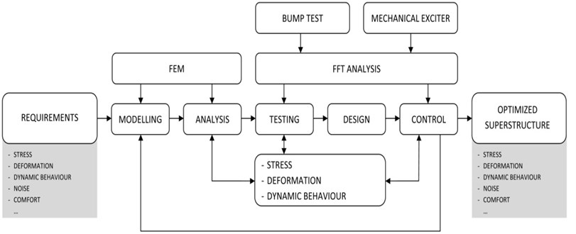
By the vibration measurements correctness of the vehicle structures and accuracy of the superstructures’ dynamic behaviour optimisation process was proved. Vibrations are used as an excellent diagnostic tool that provides information for making the correct final stand point on further activities. Many papers deal with vibration analysis of structures dynamic characteristics. In some papers [1-5] experimental results are listed and their interpretation is followed by the appropriate theoretical basis. There are a number of studies that present a numerical model based on the finite elements method [2, 6-9]. However, numerical modelling often requires experimental verification, as it is mentioned in several papers [2, 4, 10-12]. Vibrations and finite elements method are used to bring the correct stand point of the superstructures’ dynamic behaviour optimisation, which are based on the acceleration graphs [2, 5, 10-13].
When it comes to ride comfort of fire-fighters (normal exploitation conditions), the application of general guidelines in terms of module frequency is involved [14, 15]. In case of modular fire-fighting superstructures, the dominant factor is modules suspension on chassis [2, 8]. The basic concept of superstructures design is based on the choice of its elastic supports so as to avoid resonance problems. The characteristic resonant frequencies with freight motor vehicles are shown in Table 1 [14].
The modelling enables ride comfort analysis by establishing the natural frequencies and their comparison with recommended values [14, 15]. This implies the use of experimental verification of calculation models.
In extreme exploitation regimes the issue of chassis rigidity becomes significant. The purposes of modules, and therefore their construction and characteristics are different. There are water tanks, modules to accommodate and transport fire-fighters, as well as mobile workshops for the equipment storing. These are torsionally rigid and semi-rigid superstructures, and in such case undercarriage producers define guidelines regarding the connection of individual modules with the chassis. The aim is to provide free and even chassis torsion, that is limited and controlled “holding” of the chassis by torsionally more rigid modules in case of, for example, diagonal crossing the channel and/or asymmetrical coming across the curb and so on. This is achieved by elastic connections, where analysis needs to be done to determine if there is a danger of collisions between the modules.
Table 1Characteristic resonant frequencies with freight motor vehicles
Element | Eigen-frequency [Hz] |
Wheels | 11-15 |
Sprung mass | 1-1.5 |
Engine | 9-11 |
Seat | 1.5-2.5 |
Cabin | 2.5-3.5 |
Developed numerical-experimental approach (Fig. 1) allows determination of the actual structure behaviour, a reliable forecast of its response in mining, obtaining choice and decision parameters, determination of reasons for bad or loosening behaviour, assessment of exploitation lifetime and reliable operation lifetime. Due to the large number of vibration sources, determination of own frequencies and the characteristic excitation frequencies is of the great importance to the elements, subassemblies and assemblies of any modular vehicle superstructures.
2. Experiments
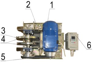
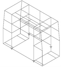
As a part of numerical-experimental approach, with idea of validation of formed discretised model [8], we prepared real physical model that should be tested (Fig. 3). Also, for this purpose special mechanical exciter is developed [3]. Excitation device is shown in Fig. 2, and it consists of following parts:
Fig. 2Mechanical exciter: 1 – electric motor, 2 – support, base of device, 3 – eccentric load, 4 – flywheel, 5 – belt transmission, 6 – frequency regulator
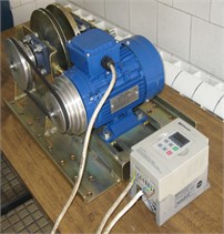
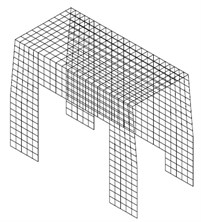
It was necessary to conduct the tests for all parts of such superstructure. Real model of auxiliary chassis is prepared [3], as well as models of front and rear segments (Fig. 3). There are prepared two variants of modules for testing, with and without plating. In such a way, we can determine the influence of module structure itself, and later, the possible differences after completing the modules with plating. Discretised calculation model of modular firefighting superstructures’ on auxiliary chassis, as well as physical model with placed testing and measurement devices, are shown in Fig. 3.
Tests of suspension parts, supports and connections of superstructure modules of firefighting vehicles are conducted in several phases: firstly, on front and rear module suspended on auxiliary chassis separately, and later together, with and without plating. Because of very wide number of loading regimes, different testing conditions and wide spectrum of achieved results, in this paper only the test results of front module mounted on auxiliary chassis should be presented.
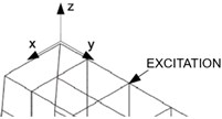
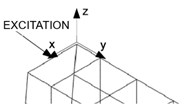
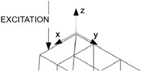
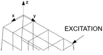
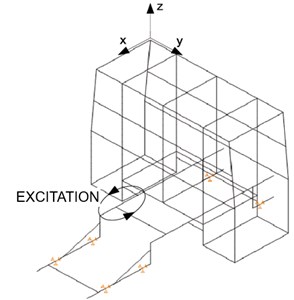
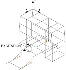
Basic classification of loading regimes has been made according to the direction of excitation; Excitation device could be placed longitudinally, transversally and diagonally, and in case of bump test, vertically. Regarding to the character of excitation frequency, it could be implemented discretely, continuously or in transient nature. At the same time, for each different loading regime and character of excitation frequency, the mass of eccentric load has been changed.
Using the acceleration sensors, we measured acceleration values along the main directions (by , and axes), since the sensors are placed in such a way. Recorded values of acceleration are presented through diagrams in time domain, giving us the change of acceleration amplitudes. With frequency analysis of acceleration diagrams in time domain, we are moving to frequency domain, with values of characteristic frequencies of structure, as well as other frequencies, caused by excitation device, design characteristics of structure and interaction of structure parts during excitation process.
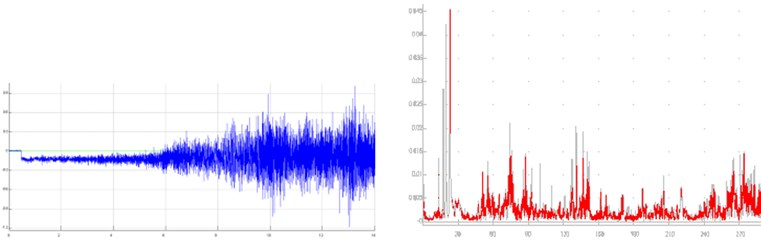
On Fig. 4 we presented the part of the results, related to bump test, for all 4 directions. As mentioned before, Segment A represents the location of placing the acceleration sensors in all main directions.
Fig. 3Discretised calculation and physical model of modular firefighting superstructures: 1 – front module, 2 – rear module, 3 – auxiliary chassis, 4 – acceleration sensors, 5 – acquisition system, 6 – excitation device. Segment A represents the upper part of front module, as the location of placing the acceleration sensors in all main directions
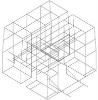
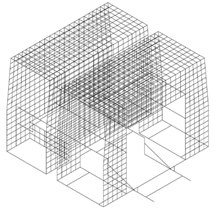

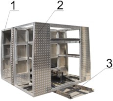
Fig. 4The part of results, related to bump test (* – excitation direction)
a) Variant 1, Longitudinally*
b) Variant 2, Transversally*
c) Variant 3, Vertically*
d) Variant 4, Diagonally*
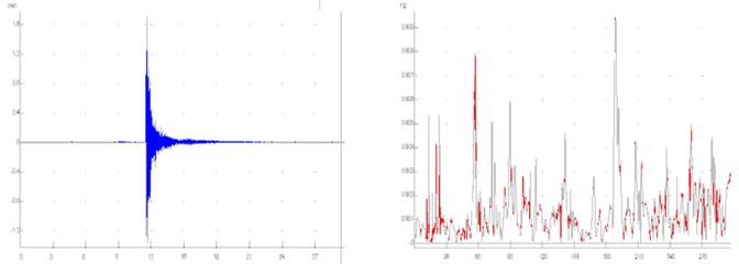
On Fig. 5 we presented the part of results, related to continuous change of excitation frequency, for 2 main directions.
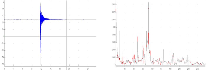
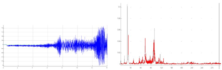
Fig. 6 and 7 present the results, shown in time and frequency domain, as well as the characteristic values of present frequencies (Tables 2, 3). Fig. 6 shows the results for previously described Variant 1 (Fig. 4), while Fig. 7 shows the results for the Variant 5 (Fig. 5).
Eigen-frequencies of firefighting superstructure front module are presented in Fig. 8.
Fig. 5The part of results, related to continuous change of excitation frequency (* – excitation direction)
a) Variant 5, Longitudinally (- plane)*
b) Variant 6, Transversally (- plane)*
Fig. 6Results for previously described Variant 1 (Fig. 4) shown in time and frequency domain
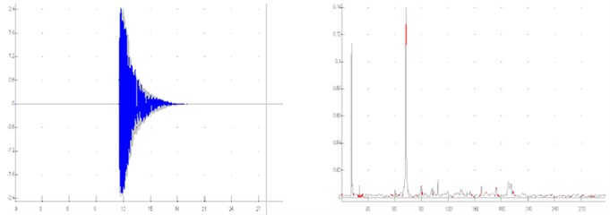
a)-axis
b)-axis
c)-axis
Fig. 7Results for the Variant 5 (Fig. 5) shown in time and frequency domain
a)-axis
b)-axis
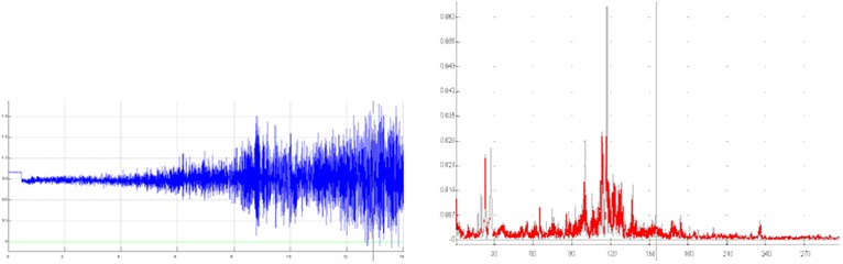
c)-axis
Table 2Acceleration amplitudes Variant 1
Direction | Present frequencies [Hz] | ||||
1 | 13 | 17 | 20 | 23 | |
-axis | 0.11 | 0.009 | |||
-axis | 0.002 | 0.005 | 0.002 | 0.004 | 0.005 |
-axis | 0.008 | 0.003 | 0.003 | ||
Table 3Acceleration amplitudes Variant 5
Direction | Present frequencies [Hz] | |||||
11 | 17 | 19 | 23 | 28 | 35 | |
-axis | 0.015 | 0.105 | 0.052 | 0.01 | ||
-axis | 0.014 | 0.028 | 0.042 | 0.045 | ||
-axis | 0.007 | 0.013 | 0.024 | 0.004 | ||
3. Numerical prototyping
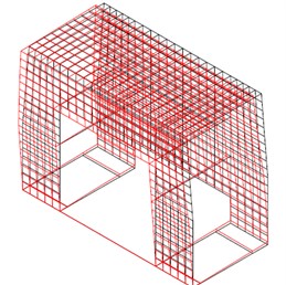
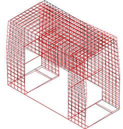
Formed numerical models of front segment of the superstructure are shown in Fig. 9. Considered type of the superstructure was modelled with 1034 nodal points, 509 beam finite elements and 820 plate finite elements. Material of all elements was aluminium with module of elasticity of 105 N/mm2, Poisson’s ratio of 0.3 and density of 2.7 10-6 N/mm3. Beam finite elements had four cases of cross-sections, mostly boxes of dimensions 80×40×4 mm and 40×40×4 mm. The thickness of the plates was 2 mm. Fig. 9 shows the beam finite elements model with the supports, as well as the plate finite elements model.
Table 4Experimental model
Eigen-frequencies [Hz] | |||
1 | 2 | 3 | 4 |
6.22 | 11.56 | 15.56 | 21.78 |
Fig. 8Eigen-frequencies of the firefighting superstructure structure
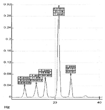
Fig. 9Numerical models of front segment of modular firefighting superstructures
a) Beam finite elements with the supports
b) Plate finite elements
Eigen-frequencies depend of the stiffness of the supports. For the stiffness of 40 dN/mm of the upper supports, amplitude fields were calculated and presented in Fig. 10, where the first and the second mode of oscillation are shown.
Comparison of the experimental and numerical results from the Fig. 8 and 11 gives that the shape of the diagrams are the same. Values of the amplitudes are very similar and a small difference in the frequencies is the consequence of the stiffness of the supports and the number of laid aluminium plates. So, we can conclude that the numerical model is correct for the further dynamic analysis.
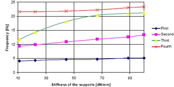
The stiffness of the supports varied from 10 dN/mm to 100 dN/mm and calculated frequencies for the first four modes of oscillation. These calculations were done for the compete model, beam and plate elements together. Vibration frequencies as a function of the support stiffness are presented in Fig. 12. It can be seen that eigen-frequencies increase with the increase of the stiffness of the supports.
Fig. 10Calculated amplitude fields
a) First mode of oscillations (4.7 Hz)
b) Second mode of oscillations (11.2 Hz)
Fig. 11Numerical results of the eigen-frequencies of the firefighting superstructure structure
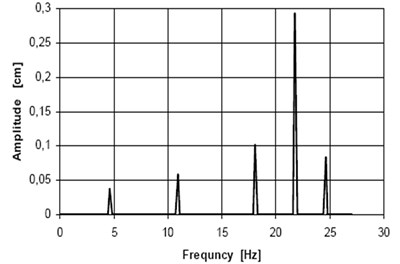
Fig. 12Eigen-frequencies for the complete model as a function of the support stiffness
4. Conclusions
Based on the above analysis, it can be concluded that shown methodology and developed models provide the ability to identify the dynamic behaviour of firefighting superstructures modules in the conditions approximate to those of real exploitation. Comparison of the experimental and numerical results verified the numerical-finite element model. As the numerical model is valid, it can be used for more complex calculations.
For this considered type of the superstructure all eigen-frequencies increase with the support stiffness. The values of the appropriate amplitudes are satisfying. But, the first and the second frequencies are too low and they are almost independent on the support stiffness. So, dynamic behaviour of this type of the superstructure is not quite satisfying. As future activities, it is necessary to analyze the influence of interconnection of separate modules, as well as the influence of module supports. Dynamic method in analysing is a very reliable method which indicated the requirement of the reconstruction and optimisation of structures. These analyses, together with previous achievements, should bring us to defining the knowledge base, which should provide real and reliable state identification of modular structures in early phases of design and product development process.
A possibility to analyse the effects of additional interconnections between individual superstructure modules, both in terms of their position, and from the standpoint of their rigidity, could be very important outcome of the present methodology. Thus, a developing contribution of the presented approach is emphasised, from the aspect of optimisation of modular superstructures supports concepts, but also in terms of reduction of current problems regarding the present failure of chassis and modules within the real use of fire-fighting vehicles.
References
-
Brkić A. D., Maneski T., Ignjatović D., Jovančić P., Spasojević Brkić V. K. Diagnostics of bucket wheel excavator discharge boom dynamic performance and its reconstruction. Eksploatacja I Niezawodnosc – Journal of Maintenance and Reliability, Vol. 16, Issue 2, 2014, p. 188-197.
-
Jovančić P., Ignjatović D., Tanasijević M., Maneski T. Load-bearing steel structure diagnostics on bucket wheel excavator, for the purpose of failure prevention. Journal of Engineering Failure Analysis, Vol. 18, 2011, p. 1203-1211.
-
Rakićević B., Mitić S., Gorotović G. The influence of modular structures stiffness to identification of their dynamic behaviour. Proceedings of the XIX International Conference MHC, Belgrade, Serbia, 2009, p. 277-282.
-
Maneski T., Jovančić P., Ignjatović D., Milošević-Mitić V., Maneski M. Condition and behavior diagnostics of drive groups on belt conveyors. Journal of Engineering Failure Analysis, Vol. 22, 2012, p. 28-37.
-
Senthil Kumar M. S., Naiju C. D., Chethan Kumar S. J., Kurian J. Vibration analysis and improvement of a vehicle chassis structure. Applied Mechanics and Materials, Vol. 372, 2013, p. 528-532.
-
Taško Maneski Structure Behavior Analysis and Diagnostic. FME Transactions XI, Belgrade, Serbia, 2004.
-
Scigliano R., Scionti M., Lardeur P. Verification, validation and variability for the vibration study of a car windscreen modeled by finite elements. Finite Elements in Analysis and Design, Vol. 47, Issue 1, 2011, p. 17-29.
-
Maneski T., Milosevic Mitic V., Andjelic N. Numerical dynamic analysis of the influence of the supports and interconnections of fire engine structural parts. 2nd International Congress of Serbian Society of Mechanics, Palic, Subotica, Serbia, Vol. 22, 2009, p. 1-7.
-
Lardeur P., Scigliano R., Scionti M. Verification and validation for the vibration study of automotive structures modelled by finite elements. Journal of Strain Analysis for Engineering Design, Vol. 48, Issue 1, 2013, p. 59-72.
-
Deulgaonkar V. R., Matani A. G. Development and validation of chassis mounted platform design for heavy vehicles. International Journal of Vehicle Structures and Systems, Vol. 6, Issue 3, 2014, p. 51-57.
-
Abad J., Valladares D., Malon H., Miralbes R., Martin C. Experimental validation of a three-axle semi-trailer finite element model for subsequent dynamic analyses. International Journal of Vehicle Systems Modelling and Testing, Vol. 8, Issue 3, 2013, p. 209-227.
-
Jafari A. A., Khoshnood A. M., Roshanian J. Dynamic modelling and verification of a flexible clustered launch vehicle. Source of the Document Proceedings of the Institution of Mechanical Engineers, Part K: Journal of Multi-body Dynamics, Vol. 224, Issues 4-1, 2010, p. 375-385.
-
Gao F., Xiong Y., Tian L., Du F., Xu G. Optimized simulation method and experimental verification on dynamic analysis of a light truck frame. Proceedings of the ASME International Design Engineering Technical Conferences and Computers and Information in Engineering Conference, Vol. 3, 2010, p. 695-701.
-
Demić M. The Optimization of Vibratory Systems of Motor Vehicles. Monography, Mechanical Engineering Faculty, Kragujevac, 1997, (in Serbian).
-
Demić M. Identification of vibration parameters for motor vehicles. Vehicle System Dynamics, Vol. 27, 1997, p. 65-88.
About this article
This article is a contribution to the Ministry of Science of Serbia funded Projects TR035045, TR035040 and TR033039.
Rakićević: The defining and realization of ideas in optimizing firefighting vehicle and elaboration of static and dynamic models; making physical models and vibration analysis. Mitić: Realization of ideas in optimizing firefighting vehicle and elaboration of static and dynamic models; making physical models and laboratory tests. Jovančić: Analysis of support structure over the measured vibration; diagrams analysis in the time and frequency domain. Ignjatović: The methodology defining for measuring and making physical models; vibration analysis. Maneski: Making numerical model using FFT analysis; structure strength analysis at firefighting vehicle.
