Abstract
The effect of earthquakes on the stability of the subway station and ground motions of surrounding rock masses, plays a key role in the seismic design of the subway station to avoid severe damage to subway station itself and adjacent structures. Most of the reported cases in the literatures on the effect of earthquake on ground motions focused on the ground motions without considering underground structures. In this study, the effect of earthquakes on the stability of the subway station, and ground motions of surrounding rock masses were investigated by using the Flac3d. The ground acceleration and safety factor of tunnel lining were highlighted. The results of the numerical analysis indicated the presence of a subway station has a great influence on ground motions, especially for the vertical ground acceleration. The ground acceleration increases with the decrease of buried depth. The amplification factor of ground acceleration is about 1.42. It exists an amplification region above the subway station with the width of 15 m. The safety factor of tunnel lining in subway station has a significant decrease in the maximum decrease rate of 67 %. The safety factor of tunnel lining except for tunnel crown and bottom changes periodic. Ground acceleration will induce extrusion or detach between surrounding rock masses and tunnel lining, and the direction of ground acceleration has a great influence on distribution of safety factor. The side wall and arch feet of tunnel lining is the most unfavorable part. Special attention should be paid to the side wall and arch feet of the subway station during seismic design.
1. Introduction
Generally, underground structures were thought to have higher seismic performance than aboveground structures, for the reason that underground structures are restrained by the surrounding soil. But many earthquake phenomena show that the present underground structures are not as good as imagined, sometimes underground structures may suffer from severe damage. For example, most of underground projects such as subway, underground parking, tunnels and underground business street suffered from serious damage in Osaka-Kobe MS 7.2 earthquake in 1995. Totally, 5 subway stations and almost 3 km running tunnel were severely damaged. Among them, the Dhaka subway station was damaged most seriously. It is estimated that the expense of tunnel recovery will be 18 billion Japanese Yen [1]. The seismic damage of underground structures [1-3] illustrates that the deformation of soil around underground structures will be very large when a strong earthquake occurs in big cities. It may cause severe damage in the weakness of underground structures and have a great influence on the integral stability of the subway station.
Some simplified methods of seismic analysis have been put forward based on the displacement response method of Winkler foundation beam. For example, based on the elastic foundation beam principle, Shukla and Rizzo (1980) put forward pseudo-static method to consider the interaction between surrounding soil and underground structures, and established the tensile model and bending model of underground structures, respectively [4]. Based on the communication theory of elastic waves in members, Koji and Shunsuke (2000) established a simplified predictive model to estimate the internal force of middle pile in subway station on the condition of vertical earthquake action [5]. The simplified method can calculate the internal force and displacement of underground structures. Nonetheless, it can’t take the interaction of underground structures and surrounding soil into consideration, which will always cause a big calculation error. With the rapid development of finite element method (FEM), numerical simulation has been widely used to study the seismic response of underground structures [6-12]. For instance, Carrilho (2014) investigated the seismic behavior of tunnels in sand through numerical simulation, and compared the results to that obtained through centrifuge tests, and further discussed the reason for the divergence of results obtained in numerical simulation and centrifuge tests [13]. Guo et al. (2013) investigated the effects of the existing subway station on the response of buildings close to the subway station, and the results show that the presence of subway station increases the flexural deformation demand of short period structures and the shear deformation demand for long-period structures [14].
However, the above mentioned laboratory tests and numerical simulation have focused on the seismic behavior of tunnel with small cross section or subway station that constructed using open cut methods. The amplification factor of ground acceleration caused by the presence of a subway station has not been deeply studied. In addition, tunnel lining of subway station that is constructed using mining method to serve as permanent supporting structures, and is directly interacting with surrounding rock masses. The stability of tunnel lining directly determines the safety of the subway station. The safety factor and the most unfavorable part have also not been studied. In this paper, the FEM software Flac3d was adopted to study the seismic response of ground motions and safety factor of tunnel lining in a subway station that is constructed using mining method with big cross section. The safety factor of tunnel lining in a subway station, and ground acceleration of surrounding rock masses were highlighted.
2. Material and method
2.1. Engineering situation
The Shangzhengjie subway station locates below the Shazhengjie street in Shpingba district, Chongqing, China. The underground structure has a circular cross section. Fig. 1 shows the cross section of the subway station. It can be seen that the station has two stories and two spans. Fig. 1 also depicts the dimensions of beams and floors in a subway station. The buried depth of subway station ranges from 15.2 m to 33.5 m. The width and height of it is 23.54 m and 20.81 m, respectively. The area of the cross section is approximate 417 m2. The thickness of secondary tunnel lining is 0.8 m. The width and length of the internal column of the Shangzhengjie subway station is 0.4 m and 1.0 m, respectively. The distance between two columns is 3.5m. The main structure is cast on site using C30 concrete. To reduce the construction of subway station on the daily life of surrounding residents, the Shazhengjie subway station is constructed using mining method. In numerical simulations, the surrounding soil conforms to the Coulomb yield criterion with an associated flow rule. The inner structures including beams and floor are simulated as elastic structural elements with Young’s modulus of 30 GPa, unit weight of 25 kN/m3, and Poisson’s ratio of 0.15. According to the geological survey report of the Shanzhengjie Subway station of Chongqing rail transit, the grade of surrounding soil was evaluated as IV. The physical and mechanical parameters of surround soil are listed in Table 1.
Table 1The physical and mechanical parameters of surrounding soil and C30 concrete
Elastic modulus (MPa) | Poisson’s ratio | Density (1×10³ kg/m3) | Cohesion (kPa) | Internal friction angle (°) | |
Surrounding rock mass | 1500 | 0.35 | 2.3 | 300 | 33 |
C30 concrete | 30000 | 0.20 | 2.4 | – | – |
2.2. Establishment of a numerical model
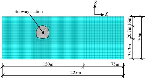
Generally, the influence of earthquake on the seismic behavior of the subway station and ground acceleration of surrounding rock masses is a three-dimensional problem. However, the length of the subway station is much larger than the size of cross section, and the properties of surrounding rock masses along the longitudinal axis of the subway station is identical according to geological survey report. Thus, the three dimensional problem can be simplified as a plain strain problem. The typical cross section view of the developed numerical model which is composed of about 12502 grip points and 6085 zones, is presented in Fig. 2. The surrounding rock masses and lining of the subway station is established using solid zones, and the internal structures of subway station, including beams and columns are established using structural beam element.
The total length of numerical model is 225 m, and the total height is 70 m. The buried depth of the subway station was set at 16 m. It can be seen that the established numerical model was not symmetric in direction. The distance between the right boundary and tunnel center is selected as 150 m to investigate the presence of subway station on ground vibration when the earthquake happened. The distance between the left boundary and tunnel center is set at 75 m to reduce the calculation burden, while the numerical results will both be greatly influenced. The internal column of the subway station was equivalent to be a longitudinal wall. The elastic modulus of columns was reduced to 4.29 GPa according to the equivalent stiffness principle. The hexahedral solid element was used to simulate tunnel lining and surrounding soil. The local damp and Rayleigh damp can be used to simulate the damp of rock mass when simulate using Flac3d. In this paper, the local damp was selected. The local damp of solid zone and structural elements are set at 0.05 and 0.02, respectively, according to the geological conditions of engineering site and local engineering experiences. Generally, earthquake wave will reflect in the boundary, which will have a great influence on the calculation results. To solve this problem, the free filed boundary was applied to the boundary of numerical model in order to avoid the earthquake reflection.
Fig. 1Dimension of Shangzhengjie subway station
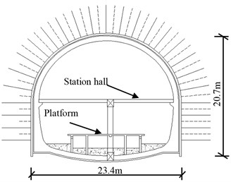
Fig. 2Typical cross section view of the developed numerical model
2.3. The characteristics of input earthquake
The KJM-UP component of the Kobe earthquake of 1995 is used as the input excitation. This is a somewhat arbitrary decision, for that there are no earthquake records on the engineering site. It should be noted that the duration time of the seismic record is approximate to 50 s. But to reduce calculation burden and get reasonable results under the condition that the numerical results will not be significantly influenced, only 8.5 s of the seismic records was selected to serve as the input excitation in this paper. The selected earthquake wave was filtered to filter out the high-frequency component in the original records using SeismoSignal that is a seismic processing software. The input earthquake excitation and its corresponding Fourier frequency after filtering are shown in Fig. 3. It can be seen in Fig. 3(b) that the maximum frequency of input earthquake is within 10 Hz. And the frequency of input earthquake mainly ranges from 1 to 5 Hz. Generally, the recorded PGA of ground motion in the horizontal direction is much larger than in the vertical direction when the earthquake happened. Thus, only earthquake excitation in horizontal direction is input in numerical analysis, earthquake excitation in vertical direction is ignored. The accelerations have been scaled according to the design ground motion in Chongqing, China. The input acceleration used in numerical analysis of Fig. 3 scaled down to a magnitude of 0.15 g for a probability of exceedance of 3 %.
Fig. 3The input Earthquake wave
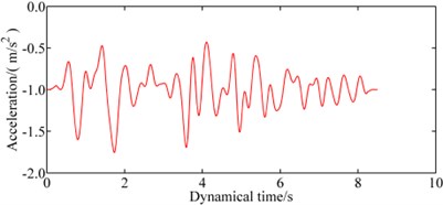
a) The acceleration versus time data of input earthquake
b) The Fourier frequency of input earthquake
2.4. The calculation method of safety factor of tunnel lining using solid elements
Generally, Flac3d provides two elements to simulate tunnel lining including the solid elements and structural shell elements. These two elements have their own advantages and disadvantages. In this paper, the solid elements were chosen to simulate tunnel lining for that solid zone can simulate the interaction between tunnel lining and surrounding soil better than structural shell elements. However, the stress of solid zones cannot directly reflect the working state and the stability of tunneling. Besides, it is difficult to conduct reinforcement calculation by using the obtained stress of the tunnel lining. To obtain the internal force of tunnel lining during an earthquake, the axial force and bending moments of tunnel lining can be calculated using calculated stress, through programming using Fish function embedded in Flac3d. The calculated stress of solid zones in Flac3d reflects the stress state of center point of solid zone. In other words, the stress in the center point of zones is accurate, which is same as that the stress of Gauss point is accurate in FEM. Two layers of zones are usually used when simulated tunnel lining using solid zones, for that the thickness of tunnel lining is thin with the value ranges from 40-80 cm. The stress in the center of two adjacent solid elements can be obtained, noted that the obtained stress is in the global system. The coordinates of these two elements were extracted to calculate the angle between local system and global systems. The obtained global stress was then transferred into local stress. It is assumed that stress of tunnel lining distributes linear. Stress in the inner and outer boundary of tunnel lining can be extrapolated. Then the axial force and bending moment can be calculated according to the theory of structural mechanics. Finally, the obtained bending moment and axial force can be used to calculate the safety factor of tunnel lining using the calculation method of columns.
3. Results and discussion
3.1. The presence of subway station on ground vibration during earthquake
Based on existing literatures, the presence of underground structures will have an influence on ground acceleration of surrounding rock masses. But the existing literatures mainly focused on studying the seismic behavior of tunnel with small section or subway station that is constructed using open cut methods. However, few literatures have studied the seismic behavior of ground acceleration of a subway station with large circular section. Besides, the ground acceleration in different depth was also not deeply studied. With the rapid development of subway, the study concerned with the influence of the subway station on the earthquake wave transmission should be made clear to guarantee the safety of the subway station and adjacent structures.
To obtain the effects of the presence of a subway station on the transmission of earthquake wave at a given condition, the numerical simulation was run twice. In the first calculation mode, the subway station is not incorporated into the calculation model. In the second calculation model, the subway station is considered. Then the ground motions of surrounding soil were calculated twice. The ground acceleration in the direction and direction of the surface point directly subway station are recorded and then compared to estimate the effects of the presence of subway station on ground motion.
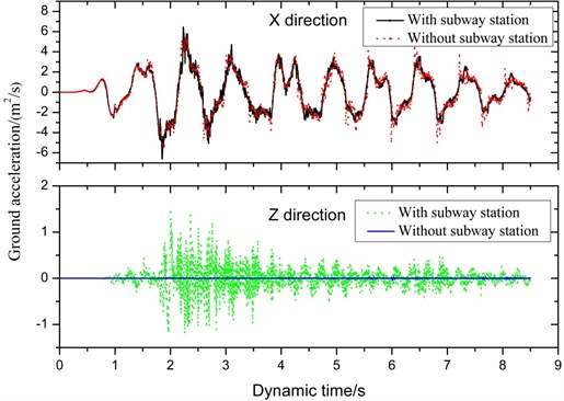
Fig. 4 shows the ground acceleration including horizontal and vertical acceleration versus time data of the ground point directly above the tunnel, with and without subway station. It can be seen that ground motions in direction are almost identical with that obtained when the station is not considered. Detail, in the first 4 seconds of input earthquake ground motion with subway station is larger than those without subway station. However, in the latter 4.5 seconds, ground motion is less than those without subway station. Ground acceleration in the direction is obviously different from those obtained when the station is not considered. Due to the acceleration in the direction is not input in numerical simulation, ground motion in the direction is close to zero. However, ground motion in direction with the considering subway station is much larger than without subway station. The peak ground acceleration is approximate to 1.5 m2/s. The presence of subway station amplifies ground acceleration, and has a greater influence on ground acceleration in direction than in direction.
Fig. 4Ground acceleration of surface point in X and Z direction
Ground motion of surrounding soil when considering subway station in different buried depth is extracted and compared to those obtained when the subway station is not considered. The acceleration versus time data were recorded using fish function during calculation. The acceleration versus time data were plotted, and maximum acceleration and its corresponding time can be found according to acceleration curve. Fig. 5 shows the ground motion in the direction and the direction along the direction, noted that ground acceleration without considering subway station fluctuates around a certain value. In Fig. 5, the dashed line reflects ground acceleration without considering subway station. The acceleration obtained considering subway station has a significant difference from that obtained without considering subway station. In the direction, the distribution of ground acceleration is similar, the peak ground acceleration nearly occurs directly above subway station, and then decrease with the increase of lateral distance between monitors point and the tunnel center, and finally keeps stable. There is an amplification region, and the amplification region increases with the decrease of depth. The amplification region reaches the maximum value when the buried depth is approximate to 15 m. There is a narrow region except the surface ground acceleration, but the length of the narrow is less and can be ignored. In the direction, the peak ground acceleration occurs in the position that is approximate to 8 m to tunnel center. Ground acceleration increases with the increase of lateral distance and reaches the peak value, then decreases with the increase of distance. In the region that is 45 m to 90 m to tunnel center, the ground acceleration is smaller than that without considering subway station. In the region that is 90 m far away from tunnel center, ground acceleration is identical with that without considering subway station. The length of amplification region is about 45 m, and the narrow region is also approximate to 45 m. Compared to ground acceleration in direction, the range of amplification region and narrow region in direction are both larger than that in direction. Which means that the vertical acceleration should be considered during seismic design, although the vertical PGA in engineering site is little. It can be concluded that due to the presence of a subway station, the horizontal ground motion caused a strong vertical ground motion near subway station during earthquake. Based on the above analysis on ground motions, it is suggested that the minimum distance between adjacent buildings and subway station should be no less than 30 m to control the influence of the subway station on adjacent buildings during earthquake.
Table 2 shows the peak acceleration that occurs in different buried depth with and without subway station. It can be seen that the peak acceleration in and direction calculated with subway station is both larger than without considering subway station. Besides, the change rule of ground acceleration with depth is similar. Ground acceleration with and without subway station, both increase with the decrease of buried depth. This is an expected result, as the amplified action of soil on earthquake wave reaches the maximum effect in surface for that there is no restraint in surface. The amplification factor is defined as the quotient of peak ground acceleration obtained with subway station to that obtained without considering subway station. It is calculated the peak amplification factor of ground in four buried depth is 1.422, 1.433, 1.433, and 1.410, respectively, from surface to 12 m below surface, noted that amplification favor was not calculated for that vertical acceleration was not input during numerical simulation. It can be seen that the amplification is approximate to 1.42, which can be used to guide the seismic design when constructing structures near to the subway station.
Table 2Peak ground acceleration in different buried depth
Depth | Acceleration in direction | Acceleration in direction | |||
Without subway station | With subway station | Amplification | Without subway station | With subway station | |
Surface | 4.59 | 6.527 | 1.422 | 0.02567 | 2.236 |
4 m to surface | 4.41 | 6.32 | 1.433 | 0.02325 | 1.98 |
8 m to surface | 4.269 | 6.119 | 1.433 | 0.01928 | 1.785 |
12 m to surface | 4.057 | 6.01 | 1.410 | 0.01664 | 1.708 |
3.2. The effect of earthquake on safety factor of tunnel lining
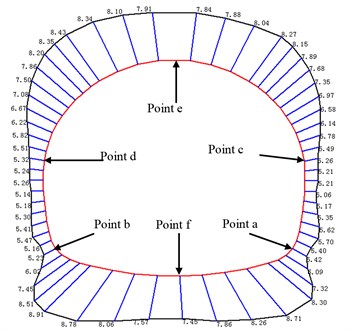
To fairly simulate the interface between tunnel lining and surrounding soil, tunnel lining was simulated using solid elements. The thickness of tunnel lining in Shazhengjie subway station is designed to be 0.6 m. Two layers of solid zones were selected to establish tunnel lining. Totally, tunnel lining was divided into 61 sections to calculate safety factor. The safety factor of tunnel lining was calculated according to the calculation method discussed in Section 2.4. The distribution of safety factor around tunnel lining before earthquake is shown in Fig. 6. It should be noted that the red line represents tunnel contour, the black line represents the value of corresponding sections of tunnel lining, and the blue line represents the connecting line that represents the calculated section of the tunnel lining. It can be seen that the distribution of safety factor around tunnel lining is symmetric before the earthquake. The safety factor of tunnel lining ranges from 5.13 to 8.37. The most unfavorable section locates in the side wall arch feet of the tunnel lining. Then the safety factor gradually increases with the increase of position of studied section, and reaches the maximum value in tunnel spandrel. This can be explained using the theory of stress deflection. Initial stress was generated by gravity or tectonic movement. The initial stress deflects around tunnel lining due to the excavation of the subway station. The lateral pressure coefficient is generally less than 1 for shallow strata. Thus the stress concentration will occur in the side wall of tunnel lining, which will then lead to larger axial force than other parts and then may lead to damage of the tunnel lining. It is suggested that special attention should paid for side wall and arch feet of tunnel lining during the construction of tunnel lining, and local thickening can be used to improve the safety factor of the tunnel lining.
Fig. 5Ground acceleration in different depth
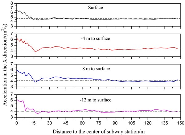
a) Ground acceleration in direction
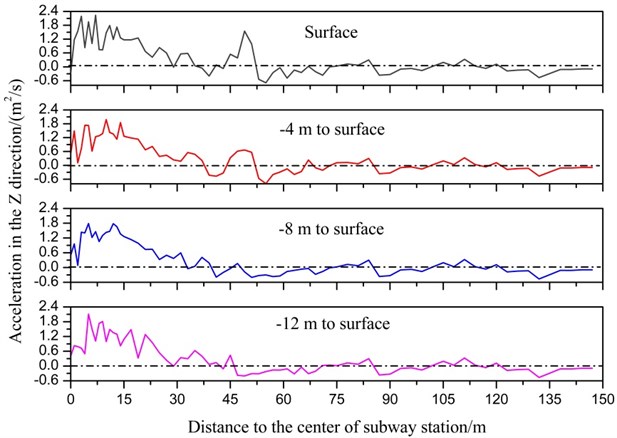
b) Ground acceleration in direction
To evaluate the influence of earthquake on safety factor of tunnel lining, six monitoring points around tunnel lining was selected (as shown in Fig. 6). Point a and b is symmetric and is located in the arch springing of tunnel lining, point c and d is also symmetric and is located in the side wall of tunnel lining, point e and f is located in tunnel crown and bottom, respectively. It should be noted that the safety factor was not an intrinsic parameter of Flac3d, thus it cannot be directly recorded during numerical simulation. To calculate the variation of safety factor during an earthquake, 425 calculation steps were divided, the calculated time of each step is set at 0.02 s. Fig. 7 shows the variation of safety factor with dynamic time. The calculated curve of safety factor was compared to the time history curve of input earthquake, noted the dashed line represents the calculated safety factor of tunnel lining and keeps stable without considering earthquake. It can be seen that a safety factor of tunnel lining has a greater decrease than that before the earthquake, which means that an earthquake has a great influence on the stability of the tunnel lining. Safety factor of six monitoring points except point e and f changes periodic. As shown in Fig. 7, the location of point a and b, and point c and d are both opposite. The change rule of point a and b, point c and d are also opposite. This phenomenon can be explained as follows. When the direction of ground acceleration is rightwards, surrounding soil in the left part of the tunnel will extrude tunnel lining and then lead to the increase of tunnel lining in the left part; reversely surrounding soil in the right part of the tunnel may detach from tunnel lining, which will lead to decrease of axial force in the bottom left part of tunnel lining, and increase of axial force in the right part of the tunnel lining. Safety factor in point e and f gradually decrease in the first 3 seconds and then keeps stable in the latter 5.5 seconds, the tendency of safety factor do not change period like that in point a, b, c, and d, for the reason that the direction of ground acceleration is oblique and is not vertical.
Fig. 6Distribution of safety factor around tunnel lining before earthquake
From Fig. 7, safety factor of point a and breaches the maximum and minimum value of a period of 5 s and 5.32 s, respectively. The distribution of safety factor around tunnel lining was depicted in Fig. 8. It can be seen in Fig. 8 that the distribution of safety factor at two different periods is opposite. In a period of 5 s, the safety factor in the upper right part of tunnel lining is larger than that before the earthquake. But safety factor in other parts of tunnel lining is less than that before the earthquake. The direction of ground acceleration near subway station is up swept as shown in Fig. 8(a). It should be noted that the direction of ground acceleration is determined according to the value and direction of ground acceleration. In a period of 5.32 s, the distribution of safety factor and direction of ground acceleration are both opposite to that of 5 s. This phenomenon can be explained as follows, when the direction of ground acceleration is up swept, surrounding soil in the upper right part of the tunnel may detach from tunnel lining, which will lead to decrease of axial force in the bottom left part of tunnel lining, and increase of axial force in the right part of tunnel lining; reversely other parts will be extruded by surrounding soil, which will lead to increase of axial force.
Fig. 7Curve of internal force and safety factor versus time
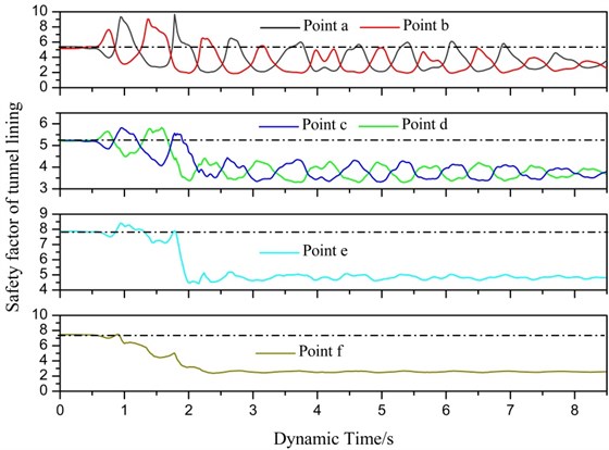
Fig. 8Direction of ground acceleration and internal force distribution in a period of 5 s and 5.32 s
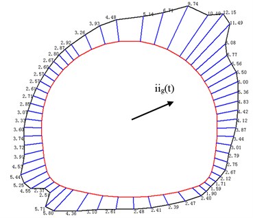
a) In a period of 5 s
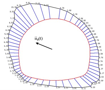
b) In a period of 5.32 s
Table 3 contains the safety factor of six monitoring points, which occurs before the earthquake and in a period of 5 s. It can be seen that that safety factor of these six monitoring points all have a significant decrease except for point b. The maximum decrease rate is 67.3 % that can provide guidance for seismic design for stability of tunnel lining in subway station on the condition that PGA is 0.15 g. In a period of 5.32 s, the varying pattern of these six monitoring points is adverse with that in a period of 5 s.
Table 3Safety factor of six monitoring points in tunnel lining
Point a | Point b | Point c | Point d | Point e | Point f | ||
Before earthquake | Value | 5.36 | 5.19 | 5.40 | 5.43 | 7.89 | 7.59 |
In a period of 5 s | Value | 2.12 | 5.25 | 4.12 | 3.33 | 4.68 | 2.48 |
Error (%) | –60.4 | 1.2 | –16.3 | –38.7 | –40.7 | –67.3 | |
In a period of 5.32 s | Value | 5.53 | 2.03 | 3.31 | 4.28 | 5.02 | 2.67 |
4. Conclusion
The effect of the earthquake on the stability of tunnel lining in the subway station that is constructed using mining method and ground motions of surrounding rock masses is investigated using numerical simulation.
There is only amplification region in direction, the width of amplification region is about 15 m. Even the PGA of vertical acceleration is generally less, but the presence of subway station greatly amplifies the vertical acceleration near subway station. There is not only the amplification region, but also narrow region. The width of amplification region and narrow region are both 45 m. The minimum distance between the subway station and adjacent buildings is suggested to be no less than 30 m to control the influence of the subway station on adjacent buildings during earthquake. The ground acceleration increase with the decrease of buried depth, but the amplification factor is generally 1.42 and is not sensitive to the buried depth.
The safety factor of tunnel lining was symmetrically distributed before the earthquake. Earthquake induced a great decrease in safety factor. The minimum safety factor is only 1.59 that is close to the limit state, and the maximum decrease rate is about 67 %. The distribution of safety factor has a close connection with the direction of ground acceleration. Because the direction of ground motion is oblique, the change frequency of safety factor in tunnel crown and bottom is less than the side wall. Ground acceleration will induce extrusion or detach between surrounding rock masses and tunnel lining, and the direction of ground acceleration has a great influence on distribution of safety factor. The side wall and arch feet of tunnel lining is the most unfavorable part. The special attention should be paid to the side wall and arch feet of the subway station during seismic design.
References
-
Iida H., Hirot T., Yoshida N, et al. Damage to Dakai subway station. Special Issue of Soils and Foundation, JSCE, 1996, p. 283-300.
-
Charles H. D., Arnon R. Damage to rock tunnels from earthquake shaking. Journal of the Geotechnical Engineering, ASCE, (GT2), 1978, p. 175-191.
-
Wang W. L., Wang T. T., Su J. J., et al. Assessment of damage in mountain tunnels due to the Taiwan Chi-Chi Earthquake. Tunnelling and Underground Space Technology, Vol. 16, 2001, p. 133-150.
-
Shukla D. K., Rizzo P. C., Stephenson D. E. Earthquake load analysis of tunnels and shafts. Proceeding of the 7th World Conference on Earthquake Engineering, USA, 1980, p. 20-28.
-
Koji U., Shunsuke S. Characteristic of the vertical seismic waves associated with the 1995 Hyogo-Nanbu (KOBE), Japan earthquake estimated from the failure of the Dakai underground station. Earthquake Engineering and Structural Dynamics, Vol. 6, 2000, p. 813-821.
-
Romanel C., Kundu T. A hybrid modelling of soil-structure interaction problems for deeply embedded structures in a multi-layered medium. Earthquake Engineering and Structural Dynamics, Vol. 22, 1993, p. 557-571.
-
Choi J. S., Lee J. S., Kim J. M. Nonlinear earthquake response analysis of 2-D underground structures with soil-structure interaction including separation and sliding at interface. 15th ASCE Engineering Mechanics Conference, New York, 2002, p. 1-8.
-
Liu H. B., Song E. X. Seismic response of large underground structures in liquefiable soils subjected to horizontal and vertical earthquake excitations. Computers and Geotechnics, Vol. 32, Issue 4, 2005, p. 223-244.
-
Abate G., Massmino M. R., Maugeri AI. M., et al. Numerical modelling of a shaking table test for soil- foundation-superstructures interaction by means of a soil constitutive model implemented in a FEM code. Geotechnical and Geological Engineering, Vol. 28, 2010, p. 37-59.
-
Shahrou I., Khoshnoudian F., Sadek M., et al. Elastoplastic analysis of the seismic response of tunnels in soft soils. Tunnelling and Underground Space Technology, Vol. 25, Issue 4, 2010, p. 478-482.
-
Chen J., Jiang L. Z., Li J., et al. Numerical simulation of shaking table test on utility tunnel under non-uniform earthquake excitation. Tunnelling and Underground Space Technology, Vol. 16, 2012, p. 133-150.
-
Tsinidis G., Pitilakis K., Trikalioti A. D. Numerical simulation of round robin numerical test on tunnels using a simplified kinematic hardening model. Acta Geotechnica, Vol. 9, Issue 4, 2013, p. 641-659.
-
Carrilho Gomes Rui Numerical simulation of the seismic response of tunnels in sand with an elastoplastic model. Acta Geotechnica, Vol. 9, Issue 4, 2014, p. 613-629.
-
Guo J., Chen J. Y., BobetA. Influence of a subway station on the inter-story drift ratio of adjacent surface structures. Tunnelling and Underground Space Technology, Vol. 35, 2013, p. 8-19.
About this article

This research is founded by the national Natural Science Foundation of China (No. 51578091). JD is supported by Australian Postgraduate Award Scholarship and Vice Chancellor and President’s Scholarships (University of South Australia)
Study design: Xiaoguang Jin and Jianghui Dong. Study conduct: Xiaoguang Jin. Data collection: Yayong Li, Zhitao Lv and Wei Luo, Data analysis: Yayong Li, Zhitao Lv and Wei Luo. Data interpretation: Yayong Li, Zhitao Lv and Wei Luo. Drafting manuscript: Yayong Li and Jianghui Dong. Revising manuscript content: Yayong Li and Jianghui Dong. All authors have read and approved the final submitted manuscript.
