Abstract
Plane vibrations of a two dimensional elastic structure are analyzed in this paper. The vibrations taking place according to the eigenmode are represented by using the method of stroboscopic geometric moiré. This requires to perform the investigation for two mutually perpendicular directions of moiré fringes. Here the superimposed moiré technique is proposed to represent both images at the same time.
1. Introduction
In precise mechanical devices there is a great number of vibrating elastic elements. Plane vibrations of a two dimensional elastic structure are analyzed in the paper. The vibrations taking place according to the eigenmode are represented by using the method of stroboscopic geometric moiré. This requires to perform the investigation for two mutually perpendicular directions of moiré fringes. Thus one is to paint geometric moiré lines in the first direction and to perform the investigation. After that one is to abolish the previously painted lines and then to paint geometric moiré lines in the perpendicular direction and perform the investigation.
In this paper the superimposed moiré technique is proposed to represent both images at the same time. Though some engineering intuition may be required in the process of interpretation of superimposed images, but the advantage of the method is the fact that both systems of mutually perpendicular and parallel in the status of equilibrium lines are painted on the structure and remain on it the whole time. Also vibrations in both mutually perpendicular directions are analyzed at the same time, while in the conventional moiré approach first the vibrations in the direction of the axis are analyzed and later vibrations in the direction of the axis are analyzed.
The analysis is based on the material described in [1-3] and other related papers.
2. Theoretical investigation of the proposed measurement procedure
One dimensional problem is investigated. Moiré lines in the status of equilibrium are represented as:
where is the coordinate, determines the width of moiré lines, is the intensity of the image.
Moiré lines in the deflected state are represented as:
where is the displacement, is the intensity of the image. In the investigation it is assumed that:
where is a constant.
Intensity of the stroboscopic image is represented as:
Investigation of moiré images of this type was performed earlier. Here gaps between moiré lines are assuned to be wider. For this purpose the following special function is introduced:
where is the width of the gap.
Moiré lines in the status of equilibrium are represented as:
Moiré lines in the deflected state are represented as:
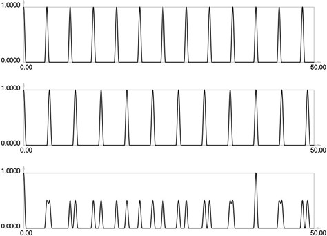
Further it is assumed that = 0.8 and = 0.1. , and for are presented in Figs. 1-5.
Fig. 1I1, I2 and Is for i = 0
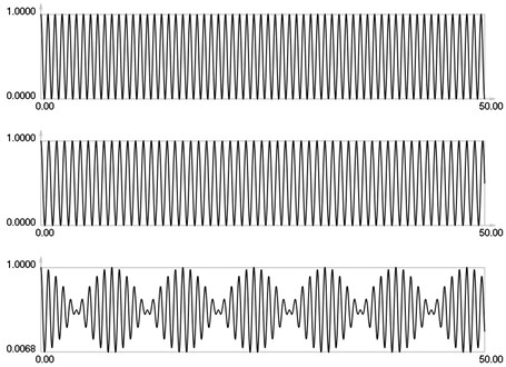
Results for = 0 correspond to the results presented earlier. Envelope of the stroboscopic image has 6 maximums inside the analyzed interval. From the results for = 1 it is seen that the envelope of the stroboscopic image has 3 maximums inside the analyzed interval. From the results for = 2 it is seen that the envelope of the stroboscopic image has 2 maximums inside the analyzed interval. From the results for = 3 it is seen that the envelope of the stroboscopic image has 1 maximum inside the analyzed interval. From the results for = 4 it is seen that the envelope of the stroboscopic image has 1 maximum inside the analyzed interval and the distance between the maximums is bigger than for the previous value of . Thus from the presented results it can be concluded that with the increase of the width of the gap the intervals between the maximums of the envelope of intensity of the stroboscopic image increase. But it is possible to interpret the displacements from moiré images with gaps. Those gaps enable to interpret both moiré images of parallel lines in a two dimensional problem simultaneously and this can be seen from the two dimensional results presented further.
Fig. 2I1, I2 and Is for i = 1
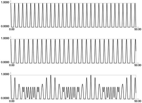
Fig. 3I1, I2 and Is for i = 2
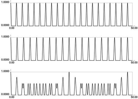
Fig. 4I1, I2 and Is for i = 3
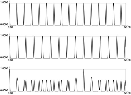
Fig. 5I1, I2 and Is for i = 4
3. Conventional stroboscopic geometric moiré images of vibrating elastic structures
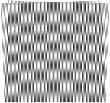
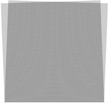
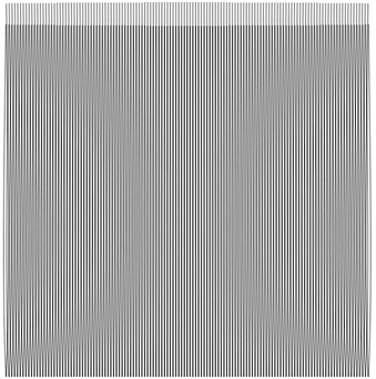
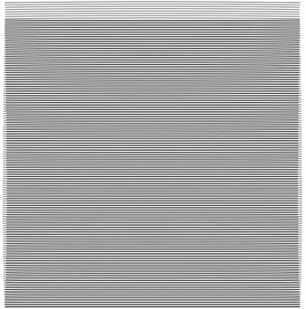
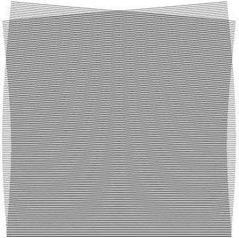
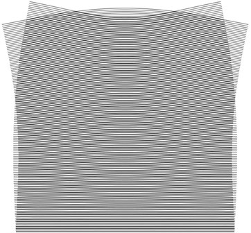
Square elastic structure with fixed lower boundary is analyzed. Stroboscopic geometric moiré images for the two conventional directions of fringes for the first eigenmode are shown in Fig. 6, for the second eigenmode in Fig. 7, for the third eigenmode in Fig. 8, for the fourth eigenmode in Fig. 9.
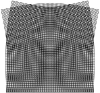
4. Superimposed moiré images of vibrating elastic structures
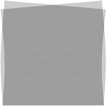
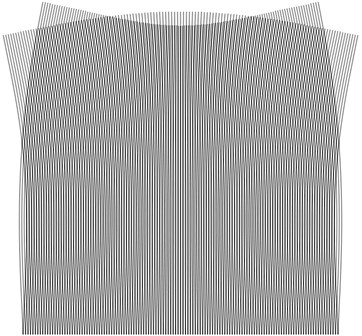
Superimposed stroboscopic geometric moiré images for the first eigenmode are shown in Fig. 10, for the second eigenmode in Fig. 11, for the third eigenmode in Fig. 12, for the fourth eigenmode in Fig. 13.
Fig. 6Stroboscopic geometric moiré images for the first eigenmode: a) the first direction of fringes, b) the second direction of fringes
a)
b)
Fig. 7Stroboscopic geometric moiré images for the second eigenmode: a) the first direction of fringes, b) the second direction of fringes
a)
b)
Fig. 8Stroboscopic geometric moiré images for the third eigenmode: a) the first direction of fringes, b) the second direction of fringes
a)
b)
Fig. 9Stroboscopic geometric moiré images for the fourth eigenmode: a) the first direction of fringes, b) the second direction of fringes
a)
b)
Fig. 10Superimposed stroboscopic geometric moiré image for the first eigenmode
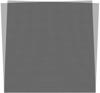
Fig. 11Superimposed stroboscopic geometric moiré image for the second eigenmode
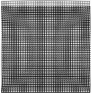
Fig. 12Superimposed stroboscopic geometric moiré image for the third eigenmode
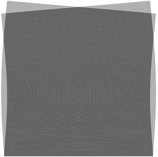
Fig. 13Superimposed stroboscopic geometric moiré image for the fourth eigenmode
5. Conclusions
The superimposed moiré technique is proposed to represent both moiré images for the analysis of plane vibrations of two dimensional elastic structures at the same time. Some engineering intuition may be required in the process of interpretation of superimposed images, but the advantage of the method is the fact that both systems of mutually perpendicular and parallel in the status of equilibrium lines are painted on the structure and remain on it the whole time. Thus vibrations in both mutually perpendicular directions are analyzed at the same time.
The proposed technique of superimposed moiré analysis of plane vibrations of two dimensional elastic structures is applicable for the investigation of vibrations of precise mechanical devices.
References
-
Ragulskis K., Maskeliūnas R., Zubavičius L. Analysis of structural vibrations using time averaged shadow moiré. Journal of Vibroengineering, Vol. 8, Issue 3, 2006, p. 26-29.
-
Saunorienė L., Ragulskis M. Time – Averaged Moiré Fringes. Lambert Academic Publishing, 2010.
-
Ragulskis M., Maskeliūnas R., Ragulskis L., Turla V. Investigation of dynamic displacements of lithographic press rubber roller by time average geometric moiré. Optics and Lasers in Engineering, Vol. 43, 2005, p. 951-962.
About this article
