Abstract
Structural vibration control technique is an appropriate and acceptable method to control structural vibration condition and dissipate structural vibration energy during severe earthquakes and violent winds. Metallic dampers are verified to be stable and effective for passive control by many scholars and engineers. Low-yield-point (LYP) steel provides a promising prospect for energy dissipation dampers widely applied in structural engineering practice. Experimental study was conducted on a novel rhombic steel plate damper in former research and numerical simulation of the hysteretic behavior of rhombic dampers was performed in this study. Mechanical performance and implementation of the novel rhombic steel plate damper is briefly introduced in this paper. The hysteretic behavior of the novel rhombic steel plate dampers made of three types of steel was investigated by testing and finite element method. It is concluded that the yield strength enhancement of the rhombic steel damper made of LYP steel is substantial. The numerical simulation results of the hysteretic behavior of the rhombic steel plate damper are similar to the experimental results for these three types of steel. The energy dissipation capability of rhombic LYP steel dampers is excellent and adequate to be used in passive control strategy for civil engineering structures.
1. Introduction
The modern vibration control concept is firstly introduced by Yao [1] into vibration control of civil engineering field, and the beginning of an era of investigation on structural control in civil engineering structures is founded in the early 1980’s. Over more than forty years of development, the active control [2], semi-active control [3] and passive control [4] including seismic isolation technique [5] of structural control strategy have been investigated and developed rapidly by a great deal of scholars and engineers over the world [6]. And the implementation of structural control technique in many practical engineering structures has been conducted in many countries and regions. The beneficial efficiency of vibration control method to protect engineering structures from severe damage and is validated in many severe earthquakes or violent winds [7]. Material science provides a vital role in vibration control field, e.g. magneto-rheological fluid [8] of magneto-rheological damper [9, 10] for active control or semi-active control, and mild steel of metallic damper for passive control.
Mild steel is always applied to structural steel components for adding structural damping and stiffness. Its elastic-plastic yield energy dissipation capacity is the main advantage for absorbing structural vibration energy during earthquakes or violent wind. So various steel dampers made by mild steel are developed by structural engineers and researchers in past three decades and applied in many structural retrofit projects of critical existing structures as to meet the energy dissipation requirements, such as school buildings, emergency command center, fire stations, hospitals and other important lifeline infrastructure. Mild steel dampers are developed in most widely-used passive control technology field all over the world by means of its elastic-plastic characteristics. The attached or substitutive mild steel damper components will provide beneficial additional lateral stiffness during minor earthquakes, and will yield much earlier than the main structures during severe earthquakes by dissipating structural vibration energy. In addition, the unique properties, such as structural simplicity, explicit seismic mitigation mechanism, satisfactory energy dissipation capacity, stable working condition and favorable replaceablility, are the most important and serviceable features of mild steel dampers [11-13].
According to the deformation behavior and energy dissipation capacity, there are mainly three types of dampers. Axial deformation mode, bending deformation mode and shear deformation mode are the commonly used elastic-plastic energy dissipation modes. The typical mild steel dampers are buckling-restrained brace (BRB) [14, 15] for axial deformation mode, Triangular plated damper (that is triangular added damping and stiffness, TADAS) [16, 17] or X-type added damping and stiffness (XADAS) [18] for bending deformation mode and shear panel damper (SPD) [19] for shear deformation mode. In recent years, a new type of rhombic steel plate damper is proposed by Shi et al [20] using LYP steel developed by Taiwan Steel Corporation. The traditional XADAS damper is affected by axial force of the damper during working because both ends of the damper are welded with the upper and lower story of the target structure for energy dissipation. The TADAS overcomes this shortcoming of XADAS, but the weld quality between the supporting leg of the triangular damper and the membrane effect will impose significant influence on the energy dissipation. The novel rhombic steel plate damper eliminate these two shortcomings of XADAS and TADAS, revealing more promising prospect of application in structural passive control technology because of its more reasonable structure detail. In recent years, the low-yield-point steel has been developed by two steel corporations in China, i.e. BAOSTEEL Corporation and ANSTEEL Corporation. This paper focuses on the deformation behavior and energy dissipation capacity of rhombic mild steel dampers. A series of physical experiments on the seismic performance and hysteretic behavior of the aforementioned rhombic steel plate damper have been carried out in previous study [21]. Investigation of the energy dissipation capacity and stability of working condition of the rhombic steel damper are performed experimentally. The purpose of this study is to reveal the hysteretic behavior and energy dissipation capacity of the rhombic dampers by finite element method (FEM) using the commercial FE program, ABAQUS, and the Von Mises stress during loading is also shown and discussed briefly.
2. The rhombic steel damper detail and loading protocol
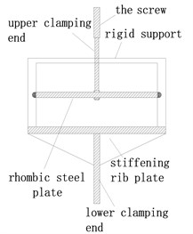
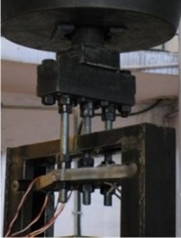
The rhombic steel plate damper can be regarded as two triangular steel plate dampers connected by their bottom edges, as shown in Fig. 1, and the fabricated rhombic steel damper specimen is also shown in Fig. 2. From structure detail of the rhombic steel plate damper, its mechanical performance can be derived by the mechanical parameters of two parallel triangular steel plate dampers. The installation diagram and the testing layout of rhombic steel plate damper are shown in Fig. 3 and 4 in former experimental study [21]. The end supporting axle of the rhombic steel plates are attached to two steel cylinders, which are subsequently installed in the rectangular steel grooves. Taking a building structure installed with this rhombic steel damper as an example. The installation mode is explained as follows. The rhombic steel damper should be installed in the inter-story with large relative displacement. The abovementioned rectangular steel groove is fixed on the upper main beam of the inter-story. The three loading screw arbor connected on each hole on the rhombic plate by blind nut were fixed to the lower main beam of the inter-story. Displacement-loading is conducted by the relative displacement between the upper and lower main beam of the inter-story. The relative displacement is the out-of-plain deformation of the rhombic steel plate damper. Major relative displacement will help to improve the effectiveness of the rhombic damper because of the metallic damper is displacement-dependent damper.
According to the test requirements, six scaled rhombic steel plate dampers using Q235 steel-plate, LYP225 steel-plate and LYP160 steel-plate are manufactured respectively according to the designed dimensions of the rhombic steel plate damper shown in Fig. 1. Each damper is made of one rhombic mild steel plate and two supporting cylinders on both sides. Three threaded holes were drilled along the short diagonal line of the rhombic plate to fix the rhombic damper with loading equipment. The cyclic testing of rhombic steel-plate dampers were performed on a 250 tons MTS electric-hydraulic servo system. Displacement-controlled mode was adopted for the cyclic testing of rhombic steel dampers. Sinusoidal displacement-loading mode is adopted with a loading frequency of 0.02 Hz. Three repeated cycles are used in every loading level. The amplitude of the transverse displacement increased from 2.5 mm to 50 mm with a displacement increment of 5 mm started from 5 mm. The loading protocol is presented in Fig. 5. The maximum loading displacement approximately reaches one-eighth of the length of steel-plate damper, which mild steel plate and two supporting cylinders on both sides. Three threaded holes were drilled along the short diagonal line of the rhombic plate to fix the rhombic damper with loading equipment. The cyclic testing of rhombic steel-plate dampers were performed on a 250 tons MTS electric-hydraulic servo system. Displacement-controlled mode was adopted for the cyclic testing of rhombic steel dampers. Sinusoidal displacement-loading mode is adopted with a loading frequency of 0.02 Hz. Three repeated cycles are used in every loading level. The amplitude of the transverse displacement increased from 2.5 mm to 50 mm with a displacement increment of 5 mm started from 5 mm. The loading protocol is presented in Fig. 5. The maximum loading displacement approximately reaches one-eighth of the length of steel-plate damper, which basically satisfies the requirement.
Fig. 1Schematic size of the rhombic mild steel plate damper
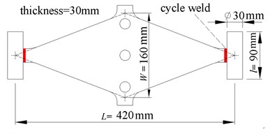
Fig. 2Specimen of the rhombic steel damper
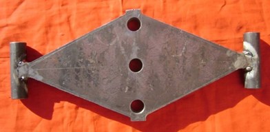
Fig. 3Installation diagram of rhombic steel plate dampers
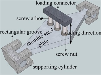
Fig. 4Testing layout of rhombic steel plate dampers
3. The hysteretic behavior simulation of rhombic mild steel plate dampers
3.1. Numerical simulation model
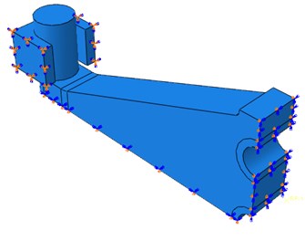
To have a better understanding of the hysteretic behavior and energy dissipation capability of the rhombic steel damper, numerical simulation using the finite element method was conducted in the commercial finite element program, ABAQUS. A three dimensional finite element model of the mild steel damper specimen was developed to properly capture the observed behavior from the cyclic testing. Different material properties were used in the finite element model to simulate LYP160, Q225and Q235 steel plate dampers. Because the damper is symmetric about both in-plane axes, 1/4 portion of the finite element model was used to simulate the hysteretic behavior of rhombic steel plate dampers. The integrated model is shown in Fig. 6, meshed quarter model and boundary conditions of a quarter of the rhombic mild steel damper are as shown in Figs. 7 and 8.
Fig. 5Loading protocol of hysteretic behavior study of rhombic steel dampers
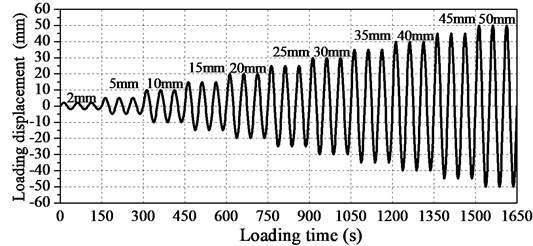
Fig. 6The integrated finite element model
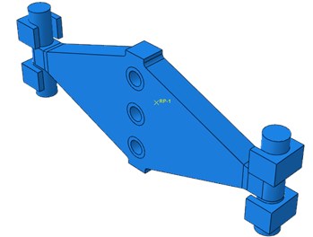
Fig. 7Meshed quarter model
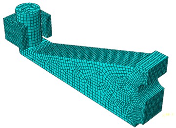
Fig. 8Model boundary conditions of quarter model
3.2. Meshed model generation, contact model and boundary conditions
The numerical model of the mild steel plate damper adopts solid elements, C3D8R linear brick element with reduced integration. The advantage is that the analysis accuracy is not obviously influenced by serious distortion of the grids. Meanwhile, the shear locking is not easy to occur under the bending load. A finer mesh generation should be accepted for purpose of overcoming the hourglass problem. In order to simulate the boundary conditions, four rectangular steel grooves with arc-shaped surface were modeled. The displacement along the loading direction (-axle) is fixed. The mild steel damper can freely move along the rectangular steel groove when the deformation at out-of-plane direction along the screw arbors occurs. But it can rotate outside the steel plate plane (-axle). Contact properties with tangential coulomb frictional behaviors are assumed between rectangular groove and cylinder in the end of steel plate damper and a frictional coefficient of 0.15 is adopted to simulate a smooth interface between them. The magnitude of the contact friction coefficient also can affect the maximum force of hysteretic curve. Meanwhile a hard contact rule is assumed in the normal direction which minimized the penetration of cylinder surface element and rectangular groove element. The contact model also is allowed for the separation of the interface. In addition, the rectangular groove is fixed completely. The rhombus steel plate is welded with steel cylinder, and strength requirement of the weld seam should be reached the strength of the main steel for dampers, so the steel plate and the steel cylinder are merged into a part without using a tie to connect them. The loading condition adopts displacement-loading, loading protocol is the same as the physical experiment testing. The loading position is located on the screw arbor boles. The loading direction is perpendicular to steel plate, along the out-of-pane direction. A coupling with full constraint is adopted to simulate the real loading condition as far as possible.
3.3. Constructive model of steel and parameters of reinforcement
The key factor of models is the stress-strain constructive property of the steel. The monotonous tensile tests of steel are conducted to obtain the relation of stress and strain. In order to accurately simulate the change of cross section in the process of large deformation, the true stress and true strain are adopted. Through the corresponding conversion formula, true stress and true strain can be gained by the corresponding nominal stress and nominal strain. The plastic strain after getting rid of elastic strain is adopted in setting up the plastic material parameters, meanwhile the necessary plastic parameter of reinforcement are applied in material property in order to simulate the real steel. A Young’s modulus of the average of test value in three specimens and a Poisson ratio of 0.3 are used for rhombic steel plate and the high strength steel properties is assumed for rectangular steel groove. A nonlinear combined hardening rule is employed to reproduce the inelastic property of the steel in order to obtain an accurate cyclic behavior, and half cyclic hardening in combined hardening is chosen. The constitutive model and property parameters of these three-type steel is derived from monotonous tensile testing of standard specimen [21]. The maximum change in yield stress of 30 MPa and a rate factor of 1.2 are adopted for Q235 steel. The maximum change in yield stress of 60 MPa and a rate factor of 1.2 are adopted for Q225 steel. And the maximum change in yield stress of 100 MPa and a rate factor of 1.5 are adopted for LYP160 steel, respectively. The material plastic property in finite element model is on the basis of the monotonous tensile test. But it can’t reflect cyclic loading features of the steel. The cyclic loading constitutive of three kinds of steel should be applied in the process of numerical simulation, because it can accurately reflect the real material characteristics in the reciprocating loading. The hardening parameters and of Q235 steel adopt the average value of three test specimens [22]. The hardening parameter and of Q225 is the same as Q235 and there is only some difference about hardening parameter , while the hardening parameter of Lyp160 steel are both different from that of Q235 steel. Therefore, the numerical simulation hysteretic curves have some difference from experimental results.
3.4. Finite element numerical simulation analyses
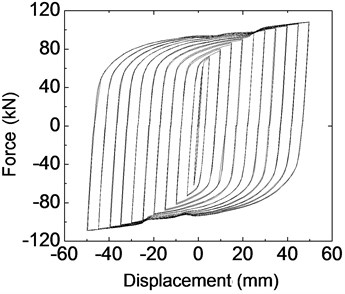
Experimental and numerical simulation hysteretic performance behavior of the novel rhombic steel damper with three kinds of steel of regular Q235, LYP225 and LYP160, are shown in Figs. 9-11. The corresponding experimental hysteretic behavior and seismic capability can be found in previous research [11]. From hysteretic curves of three kinds of steel dampers, the plump hysteretic behavior of the rhombic steel plate damper is revealed, which shows the satisfactory energy dissipation capacity of mild steel damper with these three types of steel. It is obvious that the rhombic steel-plate damper made by regular Q235 steel has a better bilinear property, while LYP steel damper, especially LYP160 reflects obvious yield stress enhancement. The hysteretic loop of LYP steel dampers is not similar to that of normal mild steel dampers and reveals a complex hysteretic rule. The yield force of LYP steel dampers is strengthened with the increase of each grade loading displacement, revealing a large set of small ring phenomenon. It is resulted that the numerical results of three kinds of dampers by FEM are fundamentally close to the testing value. Corresponding maximum displacement level, maximum damping forces in physical testing for these three-type dampers with LYP160, LYP225 and Q235 steel are 103.2 kN, 102.8 kN and 138.5 kN, respectively. But the simulated maximum damping forces of these three dampers are 100.1 kN, 108.4 kN and 134.2 kN with an error of 3.0 %, 5.4 % and 3.1 % compared with experimental results, respectively. So it is obvious that the parameters of the finite element model and hysteretic behavior analyses are substantially accurate. The finite element method can be used in this study to estimate the hysteretic behavior of rhombic steel plate dampers with mild steel with minor analytical error.
Fig. 9Hysteretic behavior of LYP160 mild steel plate dampers
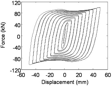
a) Experimental hysteretic behavior
b) Simulated hysteretic behavior
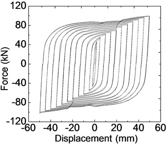
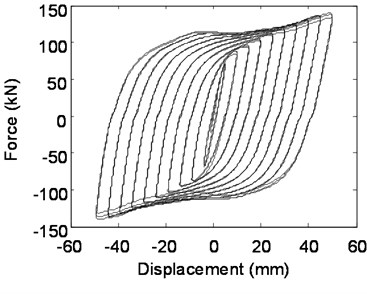
Fig. 10Hysteretic behavior of Q225 mild steel plate dampers
a) Experimental hysteretic behavior
b) Simulated hysteretic behavior
The experimental hysteretic curve shape of Q225 steel is similar as that of Q235 steel which is simulated by FEM. Another characteristic is that there is an obvious maximum force during reverse loading in each level cyclic loading. The relevant displacement is between 5 mm and 20 mm. Numerical simulation results and tested hysteretic curve of LYP160 steel damper still have some distinction. The following are the possible influence factors; the material property adopted is monotonous stress-strain and cyclic hardening with choosing suitable parameters of reinforcement. In fact, and testing process under cyclic loading should be performed on the mild steel to obtain the cyclic stress-strain relation of mild steel. Furthermore, the steel used in the testing may have certain difference with the steel used in steel tensile testing. The reinforcement model in numerical simulation adopts combined hardening mode. From the experimental hysteretic curve of LYP160 steel damper, hysteretic loop can be observed easily, which illustrate that the hardening rule of mild steel tend to isotropic hardening. And the theoretical method of the hysteretic behavior of mild dampers with LYP steel will be further investigated in the following study. This is mainly related to material properties of LYP steel.
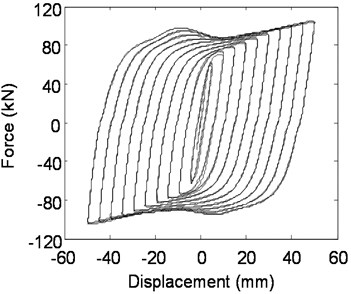
Fig. 11Hysteretic behavior of Q235 steel plate dampers
a) Experimental hysteretic behavior
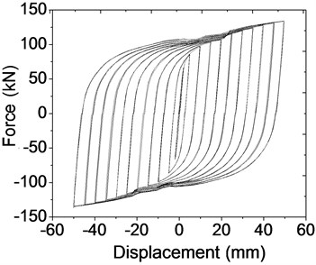
b) Simulated hysteretic behavior
According to the hysteretic behavior, the numerical simulation result of hysteretic behavior seems to behave stiffer than the experimental results, especially when the loading force changes directions. The following possible circumstances may be the cause of this phenomenon. The coupling of loading control point and loading surface adopts full constraint in order to achieve convergence. However, the relative displacement of nuts and the steel plate may occur at large bending deformation during the loading process in physical experiments, which reduces the joint rigidity between the screw and the mild steel damper. But in numerical simulation process, this decrease of joint stiffness is ignored. Another possible reason is that the friction coefficient between steel plate and rectangular groove may be larger than the actual friction coefficient.
Fig. 12Skeleton curves of three kinds of steel plate damper
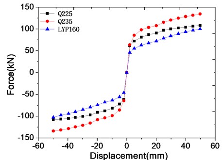
According to the hysteretic behavior from experimental results and simulated results, it is obvious that hysteretic loops of normal mild steel dampers and LYP steel dampers are substantially different with result of the yield strength hardening of LYP steel. But as shown in Fig. 12, the backbone curves of these three types of steel damper including LYP steel dampers are basically similar, revealing obvious bilinear model, which is very different from the hysteretic behavior of these three types of rhombic steel dampers. And the yield strength of LYP steel damper is apparent and lower than normal used mild steel dampers, i.e. Q235 and Q225 steel dampers. So, the LYP steel and dampers with this material is more promising for energy dissipation capability for engineering structures.
3.5. Von Mises stress contour plots
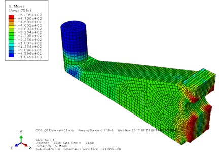
The Von Mises stress contour plots of three kinds of steel plate damper indicated that most regions of LYP160 mild steel dampers have entered plastic hardening phases, as displayed in yellow and orange regions in Fig. 13 on the contrary, the stress contour plot of Q235 and Q225 steel plate damper showed that most regions remain elastic, as is shown in Figs. 14 and 15. The Von Mises stress contour plots showed that LYP160 and Q225 steel plate damper make full use of larger plastic deformation character of mild steel because of most of most of the exterior steel yield at the maximum displacement level; therefore mild steel can dissipate more energy satisfactorily than the ordinary mild steel. Due to adopting implicit algorithm, caculation convergence for integral structure is relatively hard, so one quarter of each plate damper was simulated. The following Von Mises stress contour plots of 1/4 structure could fully reflect the response of massive structure [23, 24].
Fig. 13Mises stress contour plots of LYP160 steel dampers
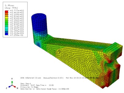
Fig. 14Mises stress contour plots of Q225 steel dampers
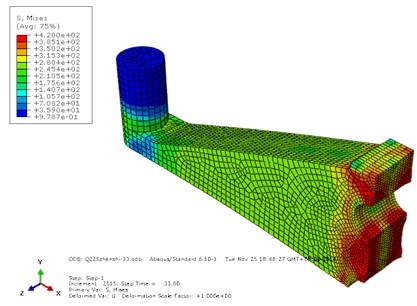
Fig. 15Mises stress contour plots of Q235 steel dampers
The existing questions are that partial elements in the boundary of holes reached the ultimate strength and damage occurred in these regions, indicating the plastic strain also have exceeded failure strain. The possible reasons are as follows. The stress concentration occurred in surrounding circle loading areas. Because several loading surfaces are restrained with the reference point, which is used to impose displacement load, meanwhile the kinematic coulping type is also adopted in order to simulate the real loading condition. Excessive distortion also occurs in partial elements around the loading surfaces as a result of excessive constraints and large deformation. Another important reason is that monotonous constitutive curve did not include the strength declining phase and the stress may go over the ultimate stress as a result of larger deformation of some elements. In virtue of the holes appeared in the middle of the rhombic steel plate damper for convenience during loading process. So the stress concentration is very obvious and should not be neglected according to current structure detail. The most likely failure mode of this type of rhombic steel plate damper is fracture along with middle line linking the three screw hole. The improvement and modification of this type of rhombic steel damper is in progress from the structure detail point of view to avoid this failure mode.
4. Conclusions
A novel rhombic mild steel plate damper is developed for dissipating structural vibration energy during severe earthquakes and violent winds. Low-yield-point mild steel have been developed in China, the hysteretic behavior of rhombic mild steel plate dampers made up of three types of mild steel are investigated by numerical simulation method using a commercial finite element program in this study. It is conclude that the numerical simulation results of three kinds of dampers by FEM are fundamentally close to the testing results with errors of less than 6 %. The hysteretic curve of LYP160 mild steel damper shows that small hysteretic loops are encircled by a large one along with the increase of loading amplitudes. Hardening rule of LYP160 steel tend to isotropic hardening instead of combined hardening. These mild steel dampers show the ideal energy dissipating capability and very promising in engineering application, especially in seismic-active areas. The numerical results by FEM and tested hysteretic curve of LYP steel damper still have certain distinction because of the complexity of the LYP steel and the difference between ideal numerical model and actual physical model. Most regions of Q225 and LYP160 mild steel dampers have entered plastic hardening phases and the energy dissipating capacity is obvious during loading process. From the Von Mises stress contour plots, it is indicated that the fracture failure of this type rhombic steel damper will occur along the line of linking the three screw arbor holes. An improved structure detail of rhombic steel dampers is under consideration to avoid this adverse failure mode.
References
-
Yao James T. P. Concept of structure control. Journal of Structure Division, ASCE, Vol. 98, Issue ST7, 1972, p. 1567-1574.
-
Zhang C. W., Ou J. P. Control strategies and experimental verifications of the electromagnetic mass damper system for structural vibration control. Earthquake Engineering and Engineering Vibration, Vol. 7, Issue 2, 2008, p. 181-192.
-
Christopoulos C., Filiatrault A. Principles of Passive Supplemental Damping and Seismic Isolation. IUSS Press, Pavia, Italy, 2006.
-
Ou J. P. Structural Vibration Control-Active, Semi-active and Smart Control. Science Press, Beijing, 2003, (in Chinese).
-
Bessason B., Haflidason E. Recorded and numerical strong motion response of a base-isolated bridge. Earthquake Spectra, Vol. 20, Issue 2, 2004, p. 309-332.
-
Olabi A. G., Grunwald A. Design and application of magneto-rheological fluid. Materials and Design, Vol. 28, Issue 10, 2007, p. 2658-2664.
-
Imaduddin F., Mazlan S. A., Zamzuri H. A design and modelling review of rotary magnetorheological damper. Materials and Design, Vol. 51, 2013, p. 575-591.
-
Yazid I. I. M., Mazlan S. A., Kikuchi T., et al. Design of magnetorheological damper with a combination of shear and squeeze modes. Materials and Design, Vol. 54, 2014, p. 87-95.
-
Dargush G. F., Soong T. T. Behavior of metallic plate dampers in seismic passive energy dissipation systems. Earthquake Spectra, Vol. 11, Issue 4, 1995, p. 545-568.
-
Chen S. J., Jhang C. Cyclic behavior of low yield point steel shear walls. Thin-Walled Structures, Vol. 44, 2006, p. 730-738.
-
Zhao J. X., Wu B., Ou J. P. A practical and unified global stability design method of buckling-restrained braces: discussion on pinned connections. Journal of Construction Steel Research, Vol. 95, 2014, p. 106-115.
-
Zhao J. X., Wu B., Ou J. P. A novel type pf angle steel buckling-restrained brace: cyclic behavior and failure mechanism. Earthquake Engineering and Structural Dyanmics, Vol. 40, 2011, p. 1083-1102.
-
Lanning J., Benzoni G., Uang C. M. The Feasibility of Using Buckling-Restrained Braces Long-Span Bridges: a Case Study. Report No.SSRP-11/09, La Jolla: University of California, San Diego, 2011.
-
Tsai K. C., Hong C. P. Steel triangular plate energy absorbers for earthquake resistant buildings. Proceedings of 1st World Congress on Constructional Steel Design, Mexico, 1992.
-
Parulekar Y. M., Reddy G. R., Vaze K. K., et al. Seismic response analysis of RCC structure with yielding dampers using linearization techniques. Nuclear Engineering and Design, Vol. 239, Issue 12, 2009, p. 3054-3061.
-
Whittaker A. S., Bertero V. V., Thompson C. L., et al. Seismic testing of steel plate energy dissipation devices. Earthquake Spectra, Vol. 7, 1991, p. 563-604.
-
Jaehyouk Choi, Daniel Y. Abebe Hysteresis characteristics of shear panel damper using SLY120. APCBEE Procedia, Vol. 9, 2014, p. 370-375.
-
Shih M. H., Sung W. P., Go C. G. Investigation of newly developed added damping and stiffness device with low yield strength steel. Journal of Zhejiang University (Science), Vol. 5, Issue 3, 2004, p. 326-334.
-
Han Q., Jia J. F., Xu Z. G., Song N. H. Experimental evaluation of hysteretic behavior of rhombic steel plate dampers. Advance in Mechanical Engineering, 2014, p. 185629.
-
Shi Y. J., Wang M., Wang Y. Q. Experimental study of structural steel constitutive relationship under cyclic loading. Journal of Building Materials, Vol. 15, Issue 3, 2012, p. 293-300.
-
Pedersen M., Olthuis W., Bergveld P. On the mechanical behaviour of thin perforated plates and their application in silicon condenser microphones. Sensors and Actuators A: Physical, Vol. 54, 1996, p. 499-504.
-
Andrea Z., Giangiacomo M., Daniele G. Low-velocity impact behavior of vitreous enameled steel plates. International Journal of Impact Engineering, Vol. 37, Issue 6, 2010, p. 673.
About this article
This research is jointly funded by the National Natural Science Fund of China (Grant No. 51208015; 51378033), Specialized Research Fund for the Doctoral Program of Higher Education of China (Grant No. 20121103120022). Their supports are gratefully acknowledged.
