Abstract
The objective is to develop a two degree of freedom model with PID controller for turning process to reduce regenerative chatter with the aim of improving productivity, quality of surface finish, tool life and reducing environmental noise caused by chatter. A system model consists of a workpiece subsystem and a cutting tool subsystem. The workpiece subsystem consists of mass, stiffness and damper. The cutting tool subsystem consists of mass, stiffness and damper. A Piezo actuator and sensor was embedded into the tool holder. A Mechatronic system has been proposed and developed for reducing tool vibration in lathe tool during machining. It consists of electrical and mechanical components; the controller is designed to control the chatter that occurs between the tool and the workpiece. The controller is used to send a feedback to the actuator. The controller is designed so that it suppresses the settling time and dampens the tool. The effective cutting stiffness and effective cutting damping are modeled as a spring and damper during machining. The original response of the system is modeled using transfer function method. Their output responses were obtained using Mat lab software.
1. Introduction
Developments in machine tools during the past few decades have raised a growing number of vibration problems. These give risk to undulations on the machined surface and excessive variations of the cutting force, which endanger the life of the tool and of the machine. The importance of dynamic performance is also increasing with proliferation of flexible manufacturing systems and unmanned operation of machine tools.
The system investigates the stability of manufacturing with slender tools and improvement of stability by optimal tool parameters using Genetic Algorithm. The objective is to suppress the chatter vibration and bring better stability during cutting process by designing a damped tool holder for existing machine tools. It is noted that the higher negative magnitude of stability boundary corresponds to best stability margin [1]. The system investigates an active vibration control of a beam using virtual instrumentation software. A single degree of freedom spring, mass damper system is actively controlled using piezoelectric elements. The optimal control is arrived at all frequencies using virtual instrumentation software. The intelligent optimal control with varying parameters is found to be more effective than a control with a fixed parameter control system [2]. The model provides a systematic approach for identifying optimum surface roughness performance in end-milling operations. The purpose of their research was to demonstrate a systematic procedure of using Taguchi parameter design in process control of individual milling machines and also to demonstrate a use of the Taguchi parameter design in order to identify the optimum surface roughness performance with a particular combination of cutting parameters in an end-milling operation [3]. Signal parameters characterizing Acoustic Emission (AE) detected during metal cutting have been theoretically correlated in a simple manner, to the work material properties, cutting conditions, and tool geometry [4]. The vibration of a tool-workpiece system in a straight turning process is induced by random disturbances and their effect on a product surface. It is noticed that for large enough level of noise, the tool and a workpiece start to vibrate due to random forcing [5]. The system utilized vibration signals to set up a multiple regression model that was capable of predicting the in-process surface roughness of a machined workpiece using a turning operation [6].
1.1. Self-excited vibration
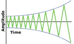
Self-excited vibration occurs when a steady input of energy is in some way modulated into vibration. Some examples of self-excited vibration are a whistle, a violin, and chatter. As seen in Fig. 1, the amplitude of this type of vibration increases with time. Chatter is a violent relative vibration between the workpiece and the cutting tool. In metal cutting, chatter is a self-excited vibration that occurs between a tool and a work piece. Chatter can be detrimental to the surface finish, as well as the tool life.
Fig. 1Self-excited vibration
1.2. PID Controller
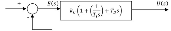
PID controller combines the advantages of Proportional, Derivative and Integral control actions. The block diagram of PID controller is shown in Fig. 2. In Proportional control the actuating signal for the control action in a control system is proportional to the error signal. For the Derivative control action the actuating signal consists of derivative of the error signal. It is also called as rate control. For the Integral control action the actuating signal consists of integral of the error signal. It is also called as reset control. For PID controller the actuating signal consists of proportional error signal added with derivative and integral of the error signal. The actuating signal is given by Eqs. (1-2):
Fig. 2Proportional-integral-derivative control
The dynamics of the control object is the largest source of difficulty in implementing control. Tuning refers to the process of setting parameter values so as to achieve satisfactory performance. Effects of each of controllers , and on a closed-loop system are summarized in the Table 1.
Table 1Effects of controller
CL response | Rise time | Overshoot | Settling time |
Decrease | Increase | Small change | |
Decrease | Increase | Increase | |
Small change | Decrease | Decrease |
2. Modeling of active vibration control system
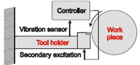
Active vibration control technique is very important for increasing life of various components and structures; this results in lower fatigue, better accuracy and low maintenance. A Piezo actuator and sensor was embedded into the tool holder. The PID controller is used to send a feedback to the actuator. The PID controller is designed so that it suppresses the settling time and dampens the tool. The active method of controlling tool setup is shown in Fig. 3.
Fig. 3Tool holder with PID controller
2.1. Mathematical modeling of dynamic cutting process
The expression for dynamic cutting force under regenerative chatter condition is given by Eq. (3):
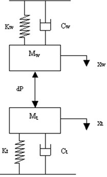
The dynamic cutting force can be modeled, as spring representing effective cutting stiffness and damper representing effective cutting damping. As the value of effective cutting stiffness increases the stability increases and conversely if the value of effective cutting damping decreases then stability increases and settling time decreases. The two-degree of freedom system of cutting tool-workpiece is shown in Fig. 4.
Fig. 4Mathematical model of the cutting system
a)
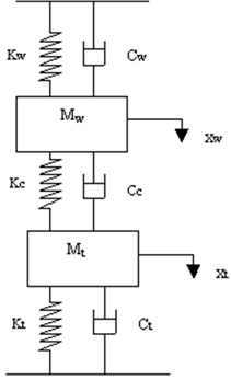
b)
Considering the system displacements, and from the static equilibrium position are positive in the downward direction, the equations of motion of the system is given by Eqs. (4-5):
The active control of the cutting tool is obtained by introducing a feedback from the output to the cutting tool by means of PID controller. The actuation force for the cutting tool is given by the feedback signal. The two-degree of freedom system with controller is as shown in Fig. 5.
Fig. 5Mathematical model of the active control cutting system
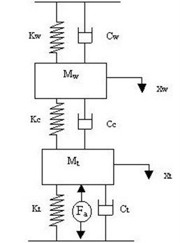
The equation of motion of the system with controller is given by Eqs. (6-7):
2.2. Transfer function
Taking Laplace Transform of the above equations can express the dynamic equations in the form of transfer functions. Considering as input, the transfer function is given by Eqs. (8-10):
where:
The effect of effective cutting stiffness on system stability and values are tabulated as shown in Table 2. A generalized program is written by transfer function method using Matlab. By substituting the tabulated values in the Mat lab program, the step response obtained is shown in Figs. 6-15.
Table 2Cutting tool parameters
S. No. | (kN/m) | (kN s/m) | (kN/m) | Values of other parameters |
1 | 300 | –0.1983 | 2000 | 1.604 kg, 563 kN/m, 0.0647, 2.48 kg, 0.3254 |
2 | 800 | –0.6218 | 3000 | |
3 | 1300 | –0.8754 | 4500 | |
4 | 1800 | –0.9186 | 5500 | |
5 | 2300 | –1.0396 | 7000 |
3. Step response (without PID Controller)
Fig. 6Step response for Kt= 2000 kN/m, Kc= 300 kN/m and Cc= –0.1983 kN s/m
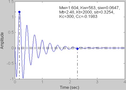
Fig. 7Step response for Kt= 3000 kN/m, Kc= 800 kN/m and Cc= –0.6218 kN s/m
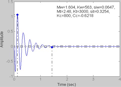
Fig. 8Step response for Kt= 4500 kN/m, Kc= 1300 kN/m and Cc= –0.8754 kN s/m
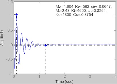
Fig. 9Step response for Kt= 5500 kN/m, Kc= 1800 kN/m and Cc= –0.9186 kN s/m
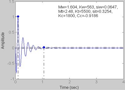
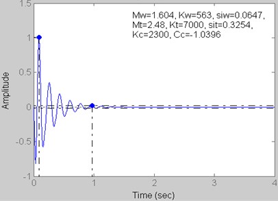
Fig. 10Step response for Kt= 7000 kN/m, Kc= 2300 kN/m and Cc= –1.0396 kN s/m
4. Step response (with PID Controller)
Fig. 11Step Response for Kt= 2000 kN/m, Kc= 300 kN/m and Cc= –0.1983 kN s/m
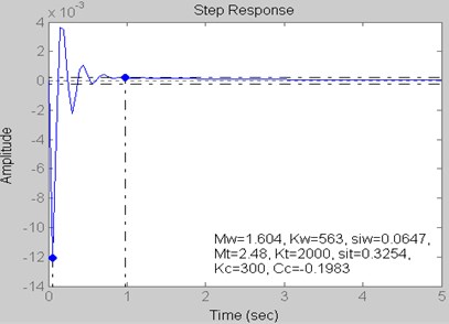
Fig. 12Step response for Kt= 3000 kN/m, Kc= 800 kN/m and Cc= –0.6218 kN s/m
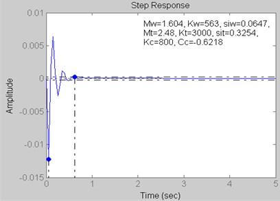
Fig. 13Step response for Kt= 4500 kN/m, Kc= 1300 kN/m and Cc= –0.8754 kN s/m
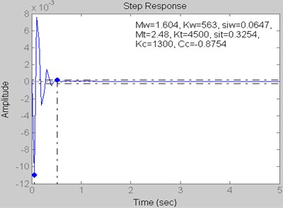
Fig. 14Step response for Kt= 5500 kN/m, Kc= 1800 kN/m and Cc= –0.9186 kN s/m
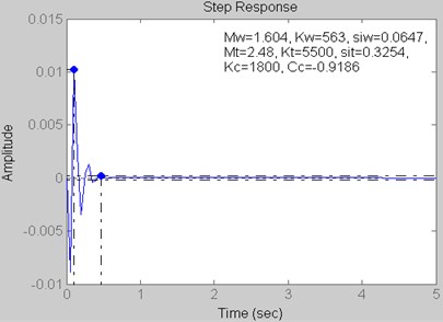
Fig. 15Step response for Kt= 7000 kN/m, Kc= 2300 kN/m and Cc= –1.0396 kN s/m

5. Result
The values of Settling Time and Peak Amplitude for different values with and without using PID Controller are tabulated in Table 3.
Table 3Step response values
Figure | Without PID controller | With PID controller | ||
Settling time (sec) | Peak amplitude (microns) | Settling time (sec) | Peak amplitude (microns) | |
Fig. 6 and 11 | 2.28 | 1.16 | 0.98 | –0.01 |
Fig. 7 and 12 | 1.44 | 1.06 | 0.62 | –0.01 |
Fig. 8 and 13 | 1.26 | 1.06 | 0.51 | –0.01 |
Fig. 9 and 14 | 1.05 | 1.01 | 0.46 | 0.01 |
Fig. 10 and 15 | 0.96 | 1.01 | 0.36 | 0.01 |
6. Conclusions
The effect of effective cutting stiffness on system stability has been analyzed using Matlab. The Modeling is performed by transfer function method. The controller is used to reduce the settling time. It is observed that settling time and peak amplitude is considerably decreased when PID controller is used than that of without PID controller.
References
-
Alwarsamy T., Balasubramanian R., Raja Kumar K., Sankarasubramanian B. Improvement of stability by optimal parameters using genetic algorithm. Advances in Vibration Engineering, Vol. 2, Issue 4, 2003, p. 388-404.
-
Singh Harpreet, Singh S. P., Agarwal V. P. Active vibration control of a beam using virtual instrumentation software. International Conference on Smart Materials, Structures and Systems, India, 1999, p. 443-448.
-
Yang John L., Chen Joseph C. A systematic approach for identifying optimum surface roughness performance in end-milling operations. Journal of Industrial Technology, Vol. 17, Issue 2, 2001.
-
Keraita J. N., Oyango H. J., Misoi G. K. Lathe stability charts via acoustic emission monitoring. African Journal of Science and Technology, Science and Engineering Series, Vol. 2, Issue 2, 2001, p. 81-93.
-
Lipski J., Litak G., Rusinek R., Szabelski K., Teter A., Warminski J., Zaleski K. Surface quality of a work material influence on vibrations in a cutting process. Journal of Sound and Vibration, Vol. 252, Issue 4, 2002, p. 729-737.
-
Huang Luke, Chen Joseph C. A multiple regression model to predict in-process surface roughness in turning operation via accelerometer. Journal of Industrial Technology, Vol. 17, Issue 2, 2001.
-
Karkosch H. J., Preumont A. Recent advances in active damping and vibration control. 8th International Conference on New Actuators, Germany, 2002, p. 248-253.
-
Mauri E., Kato S., Hashimoto M. The mechanism of chatter vibration in a spindle-workpiece system: Part 1 – Properties of self-excited chatter vibration in spindle-workpiece system. Journal of Engineering for Industry, Vol. 110, 1988, p. 236-241.
-
Mauri E., Kato S., Hashimoto M. The mechanism of chatter vibration in a spindle-workpiece system: Part 2 – Characteristics of dynamic cutting force and vibration energy. Journal of Engineering for Industry, Vol. 110, 1988, p. 242-247.
-
Mauri E., Kato S., Hashimoto M. The mechanism of chatter vibration in a spindle-workpiece system: Part 3 – Analytical considerations. Journal of Engineering for Industry, Vol. 110, 1988, p. 248-253.
-
Lago T. L., Hakansson Lars Performance of a chatter control system for turning and boring applications. 4th GRACM Congress on Computational Mechanics, 2002.
-
Andren L., Hakansson L., Claesson I. Active Vibration Control of Boring Bar Vibrations. Blekinge Institute of Technology, Sweden, 2004, p. 139-196.
-
Tobias S. A. Machine Tool Vibration. John Wiley, New York, 1965.
-
Willis M. J. Proportional-Integral-Derivative Control. University of Newcastle, 1999.
About this article

