Abstract
The behavior of rope-guided conveyances is so complicated that the rope-guided hoisting system hasn’t been understood thoroughly so far. In this paper, with user-defined functions loaded, ANSYS FLUENT 14.5 was employed to simulate the flow-induced vibration of rope-guided conveyances under different ventilation air speed. With rope-guided mine cages taken into account, results show that the ventilation affects the lateral displacement of conveyance greatly. With the increase of ventilation air speed, the maximum lateral and side displacements of ascending conveyances also increase, while those of descending conveyances don’t always increase, because the ventilation air flows downcast. With the thrust bearings equipped with the hoist rope attachment and the tail rope attachment, the rotation of conveyance about vertical axis is very small.
1. Introduction
Shaft hoisting system plays a significant role in underground mining industry, which is used to transport ore, equipment and personnel, and is called “the throat” of shaft. Rope guide is characterized by short installation time, lower capital costs, lower maintenance requirements and smooth travel [1, 2]. Rope guides have been used widely in mining shafts. However, the stiffness of rope guides is very small, so the horizontal displacement of rope-guided conveyances is larger than that of fixed-guided conveyances. Aerodynamic forces, residual unbalanced head/tail rope torque and Coriolis force are perceived as the main types of disturbing forces which induce the transverse displacement of rope-guided conveyances [2-5].
Aerodynamic force results from the asymmetrical air flow around the conveyance. Slonina and Stuhler [1] reported that at Merlebach mine, the rope-guided cage was displaced almost 600 mm towards the shaft wall when two cages were travelling side by side against the ventilation air flow, and they found out that the air flow plays an important role in generating oscillation of rope-guided conveyance. Based on the empirical formula, the magnitude of the steady aerodynamic force depends on the relative velocity between ventilation air speed and conveyance speed [2-5]. Aerodynamic buffeting force was measured by Hurlin [6] on a scale model and he gave an empirical model to predict the buffeting force. However, the literature about the behavior of rope-guided conveyance is quite less, and the effect of ventilation on the moving rope-guided conveyance has not been reported.
A fluid-structure interaction (FSI) method based on computational fluid dynamic (CFD) was presented to simulate the lateral oscillations of rope-guided conveyances [7]. In this study, we use the FSI method to investigate the behaviour of rope-guided conveyances when different ventilation air speeds are applied to shaft.
2. Numerical model
The detailed fluid-structure interaction (FSI) technique to simulate the lateral oscillations of rope-guided conveyances has been presented in our previous article [7].
2.1. Mathematical model
Fig. 1 gives the mathematical model of rope-guided hoisting system. According to the Newton’s second law, the equations of horizontal motion for the conveyance in -direction and -direction can be represented as:
where represents the mass of conveyance, and represent the displacements of conveyance in and respectively, and represent the disturbing forces on conveyance in -direction and -direction respectively, and represents the lateral equivalent spring stiffness for conveyance. The lateral equivalent spring stiffness of rope-guided conveyance can be found in references [4, 7].
The equations of rotation for the conveyance about the vertical axis can be represented as:
where represents the mass moment of inertia of the conveyance about the vertical axis, represents the angular displacements of conveyance about vertical axis, represents total disturbing torque exerted on the conveyance about vertical axis, and represents the equivalent angular spring stiffness for conveyance about vertical axis. In some Chinese mine hoisting practices, the hoist rope attachment and the tail rope attachment are equipped with the thrust bearings, which can eliminate the torsion from hoist rope and tail rope, so the total disturbing torque only takes the aerodynamic moment on the conveyance about vertical axis into consideration.
Fig. 1Mathematical model of rope-guided hoisting system
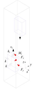
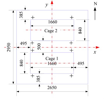
Fig. 2Shaft layout of mine cages
2.2. Shaft parameters
Fig. 2 gives shaft layout of mine cage, and the main parameters of shaft layouts are given in Table 1. The ventilation air speeds are 0, 2 m/s, 4 m/s, 6 m/s and 8 m/s respectively. The time-speed diagram in vertical direction of mine cage is shown in Fig. 3.
2.3. CFD modelling
The commercial code, ANSYS FLUENT 14.5, has been employed to simulate these cases with PISO scheme. In this study, the ventilation air flow is downcast, so the upper entrance is a velocity inlet boundary condition and the lower exit is pressure outlet boundary condition. All other boundary conditions are no slip at the wall. User-defined functions (UDFs) were written to define the vertical velocity of conveyances and to solve the equations of horizontal motion for conveyances with the Newmark-beta method 1/2, 1/4) [8]. The movements of conveyance have been implemented using a dynamic mesh with the local cell remeshing method in ANSYS FLUENT. As the local cell remeshing method only affects the tetrahedral cell types in the mesh [9], tetrahedral meshes were generated in the domain. Fig. 4 illustrates the Compute meshes and there are about 4×10⁵ control volumes. And the shear-stress transport (SST) model [10] was used for the turbulent air flow. These five transient cases were resolved using a characteristic time step of 0.002 seconds, and the total time is 16.6 seconds for the hoisting conveyances. There are 8300 time steps in total and 50 iterations for each maximum time step to resolve each case. About 20 h of CPU time in a 4-nodes HPC cluster were required to complete each numerical simulation.
Fig. 3Time-speed diagram in vertical direction
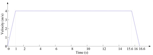
Fig. 4Compute meshes
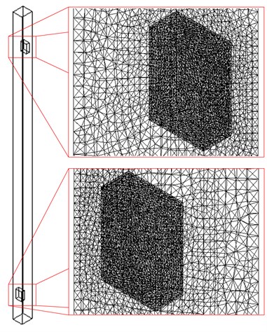
Table 1The main shaft parameters
Hoist ropes | 4 off, 13 mm, 0.586 kg/m |
Tail ropes | 1 off, 26 mm, 2.33 kg/m |
Guide ropes | 4 off per cage, 24 mm, 3.22 kg/m |
Conveyance mass | 1.6 t |
Hoisting distance | 62.4 m |
Hoisting speed | 4.0 m/s |
Payload | 0.8 t |
Method of tensioning | Weight |
Tension load indicated | 1000 kg per guide rope |
Ventilation direction | Downcast |
3. Results and discussion
3.1. Results
When two cages pass each other, pressure contours under different ventilation air speed are shown in Fig. 5. Here, denotes the ventilation air speed.
Fig. 5Pressure contours under different ventilation air speed
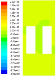
a)0 m/s

b)2 m/s

c) m/s

d)6 m/s

e)8 m/s
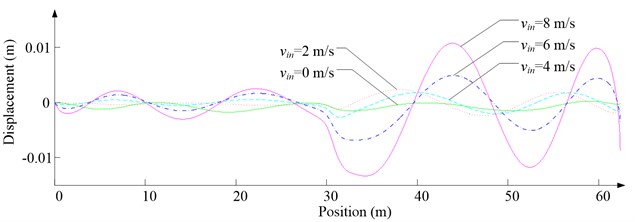
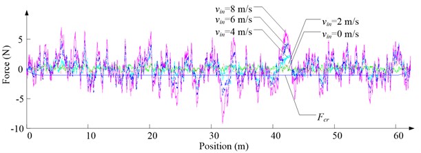
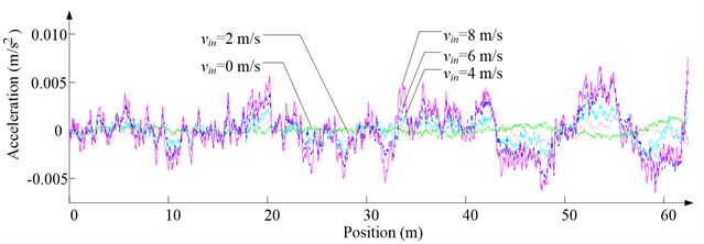
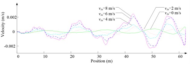
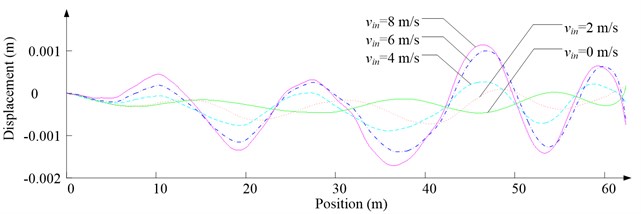
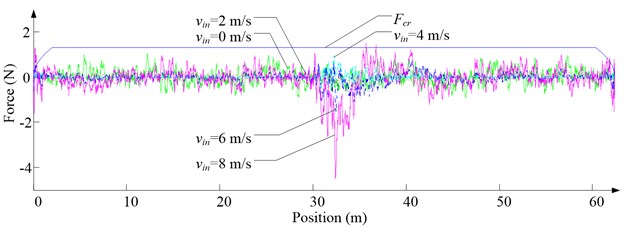
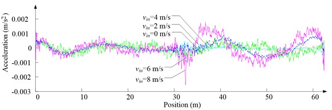
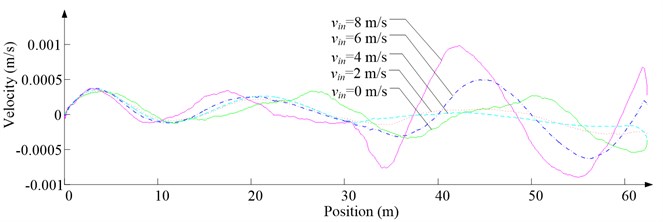
Fig. 6Simulation results for ascending cage 1 in north-south direction
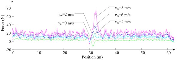
a) Lateral aerodynamic force
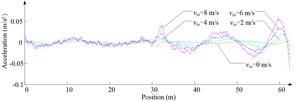
b) Lateral acceleration
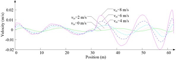
c) Lateral velocity
d) Lateral displacement
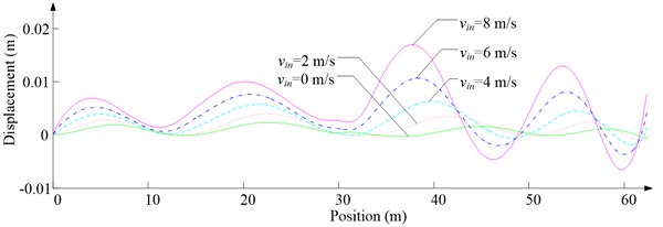
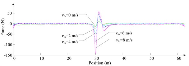
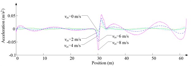
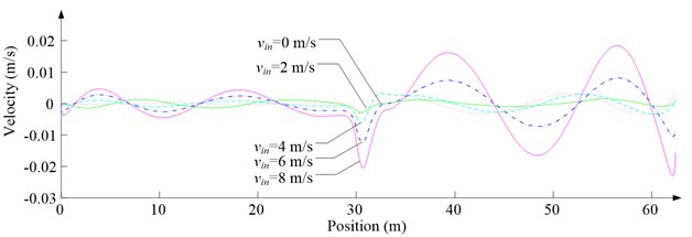
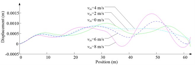
Fig. 6 shows the lateral aerodynamic force, lateral acceleration, velocity and displacement of ascending cage 1 in north-south direction, and Fig. 7 shows the lateral aerodynamic force, lateral acceleration, velocity and displacement of descending cage 2 in north-south direction. Fig. 8 shows the lateral aerodynamic force, lateral acceleration, velocity and displacement of ascending cage 1 in east-west direction, and Fig. 9 shows the lateral aerodynamic force, lateral acceleration, velocity and displacement of descending cage 2 in east-west direction. Here, denotes the Coriolis force.
Fig. 7Simulation results for descending cage 2 in north-south direction
a) Lateral aerodynamic force
b) Lateral acceleration
c) Lateral velocity
d) Lateral displacement
Fig. 8Simulation results for ascending cage 1 in east-west direction
a) Side disturbing force
b) Side acceleration
c) Side velocity
d) Side displacement
Fig. 9Simulation results for descending cage 2 in east-west direction
a) Side disturbing force
b) Side acceleration
c) Side velocity
d) Side displacement
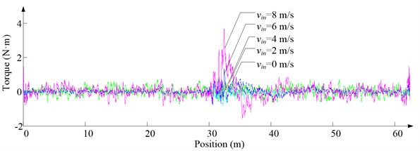
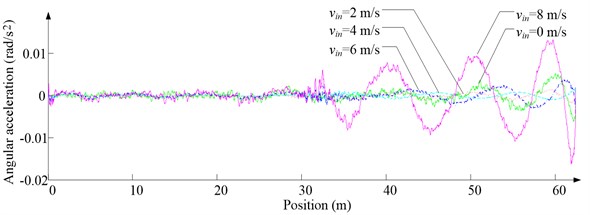
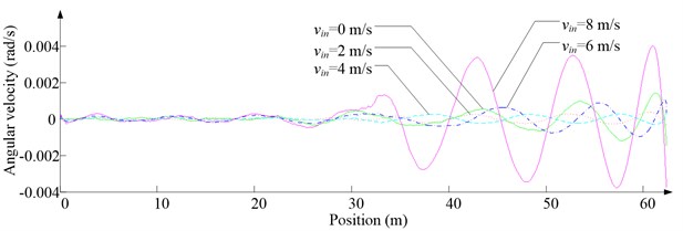
Fig. 10Simulation results for ascending cage 1 around z-axis
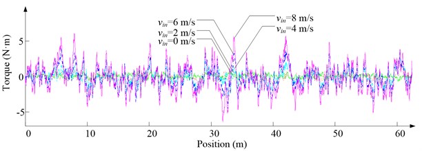
a) Aerodynamic torque
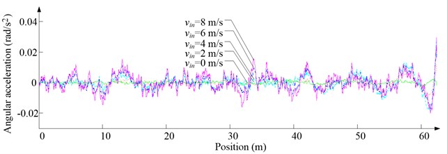
b) Angular acceleration
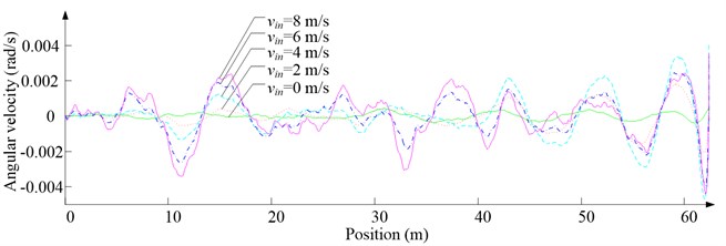
c) Angular velocity
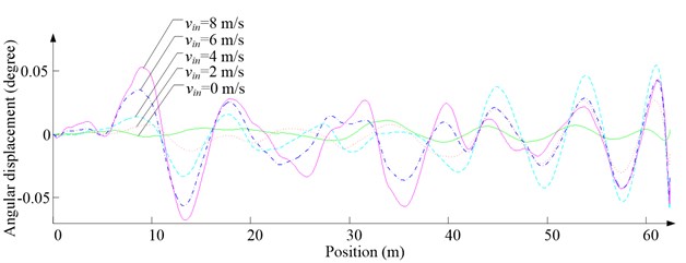
d) Angular displacement
Fig. 11Simulation results for descending cage 2 around z-axis
a) Aerodynamic torque
b) Angular acceleration
c) Angular velocity
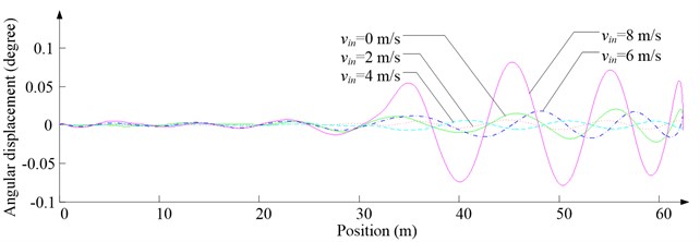
d) Angular displacement
3.2. Discussion
As Fig. 5 shows, the ventilation directly affects the pressure contours around the cages. As Fig. 6-9 show, the ventilation has a significant effect on horizontal displacement of conveyance, because the aerodynamic force is directly related to the ventilation air speed. As Fig. 10 and Fig. 11 show, the rotation of conveyance about vertical axis is very small, because the hoist rope attachment and the tail rope attachment equipped with the thrust bearings eliminate the torsion from hoist rope and tail rope.
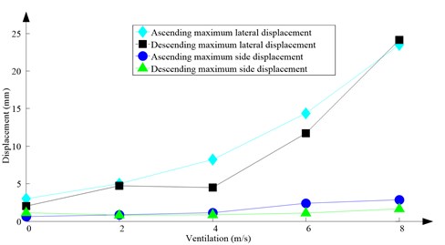
As Fig. 12 shows, with the increase of ventilation air speed, the maximum lateral and side displacements of ascending conveyances also increase, while those of descending conveyances do not always increase, because the ventilation air flows downcast. And the maximum lateral displacement is much larger than the maximum side displacement, because the lateral aerodynamic forces are much larger than the side aerodynamic forces.
Fig. 12Maximum horizontal displacement
4. Conclusions
With the UDFs loaded by Fluent, this paper investigates the behavior of rope-guided conveyances under different ventilation air speed. Results show that the ventilation greatly affects the deflection of rope-guided conveyances. When designing a rope-guided hoisting system, CFD simulation is a useful tool to predict the behavior of rope-guided conveyance.
References
-
Slonina W., Stuhler W. Safety problems posed by rope shaft guides. Research Report, Commission of the European Communities (Mines Safety and Health Commission), Luxembourg, 1980.
-
Greenway M. E., Jujnovich B. A., Grobler S. R., Baroni N. P. Behaviour of rope-guided conveyances. Proceedings of Mine Hoisting 2000, 5th International Conference, SAIMM Symposium Series S25, Johannesburg, South African, 2000, p. 89-98.
-
Hamilton R. Rope-guided hoisting for 2000 and beyond – engineering rope guides for deep shafts. Proceedings of Mine Hoisting 2000, 5th International Conference, SAIMM Symposium Series S25, Johannesburg, South African, 2000, p. 83-88.
-
Krige G. J. Guidelines for the design of rope guides. International Conference on Hoisting and Haulage 2005, Perth, Australia, 2005, p. 275-283.
-
Darling P. SME Mining Engineering Handbook. 3rd Edition. Littleton, Society for Mining, Metallurgy, and Exploration, Inc., 2011.
-
Hurlin R. The Aerodynamic Buffeting Force between Passing Mine Cages. Ph.D. Thesis, University of the Witwatersrand, 1993.
-
Wu R. Y., Zhu Z. C., Chen G. A., Cao G. H., Li W. Simulation of the lateral oscillation of rope-guided conveyance based on fluid-structure interaction. Journal of Vibroengineering, Vol. 16, Issue 3, 2014, p. 1555-1563.
-
Newmark N. M. A method of computation for structural dynamics. Journal of Engineering Mechanics Division, ASCE, Vol. 85, Issue 3, 1959, p. 67-94.
-
ANSYS FLUENT User’s Guide. Release 14.5, 2012.
-
Menter F. R. Two-equation eddy-viscosity turbulence models for engineering applications. AIAA Journal, Vol. 32, Issue 8, 1994, p. 1598-1605.
About this article
This work was supported by the Major State Basic Research Development Program of China (973 Program) (Grant No. 2014CB049404), Program for Changjiang Scholars and Innovative Research Team in University (Grant No. IRT1292) and the Project Funded by the Priority Academic Program Development of Jiangsu Higher Education Institutions (PAPD).
The authors acknowledge Dr. Geoffrey J. Krige, Dr. Malcolm E. Greenway and Rodney S. Hamilton for their counsel and articles.
We are grateful to the Advanced Analysis and Computation Center of CUMT for the award of CPU hours to accomplish this work.
