Abstract
The paper presents the parameters of the pressure wave incident on minehunter hull structure modeled on the simplified vessel hull of Kormoran II project. The pressure wave is caused by the sea mine explosion on wet board of the ship and propagates in the sea. To describe the pressure wave procedure pressure formulas which can be implemented on programs CAE based on the Finite Element Method (FEM) was used. The way of modeling short – term issues using FEM and constitutive equations describing the explosion of TNT in the sea was described. Naval mines used by the Polish Navy were characterized. Equivalents of selected explosives in relation to the TNT were posted. Geometry of mine destroyer was mapped as a shell – beam model. The results of the pressure wave incident on the hull as a function of charge weight and the location of the epicenter of the explosion was presented. Formulated conclusions and comments.
1. Introduction
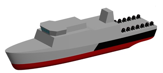
In September 2013, Inspectorate of Polish Navy Armament signed a contract to build new ships for combating and setting mines codenamed “Kormoran II”. She has to be adapted to operate in the Polish economic zone, as well as in tactical operations in the Baltic and the North Sea. Basic assumptions tactical – technical shown below [1]:
• displacement: max: 850 tons;
• length: 58.00 m;
• width: 10.30 m;
• forecastle deck height: 6.40 m;
• the height of the main deck, aft: 4.70 m;
• draft: 2.60 m;
• speed: not less than 15 kt;
• range: not less than 2,500 nautical miles.
Fig. 1The Kormoran II minehunter designed for the minefield setting
Due to the destination of the ship should be examined cases in which the ship may be exposed to the sea mine explosion. It is therefore necessary to distinguish underwater explosion (UNDEX) derived from the enemy charge and the explosion on board in case of a failure while setting up mine warfare. The effects of explosions are difficult to predict. In case of contact explosions which are explosions on board of the ship, it is possible to determine the pressure distribution derived from such an explosion by using the CONWEP procedure which is not described further.
2. Underwater explosion
Nowadays, many CAE programs uses CONWEP procedure to simple calculations for free explosions in the air. The value of pressure is determined by the program based on the weight of the load and then using TNT equivalents calculated for the respective loads. A similar situation can be applied to underwater explosions. In order to properly calculation of pressure wave incident on the structure shall be familiar with the phenomenon, analytical description of the pressure wave used by the program and simplifying assumptions.
Underwater explosion is a rapid equilibrium violation caused by detonation of explosive in water. During explosion the charge is converted from solid into product of volume equal to volume of explosive material, temperature range 3300 K and pressure 14000 MPa. With so much pressure gas bubble is formed which causes a spherical shock wave that propagates in the medium [3, 4]. The first of the researchers of this phenomenon was the R. H. Cole whose works are the basis for further research. The parameters of the shock wave and the gas bubble parameters are being investigated further. Currently the main of researchers are T. L. Geers, K. S. Hunter and C. K. Park. Most previous publications describes the behavior of gas bubbles, often omitting same shockwave. In this work, omit the description of the bubble in order to focus on the pressure wave from the detonation. This wave in the initial stage moves at a speed of the order of 5000 – 8000 m/s. Then, the water molecules act on the water layer adjacent losing speed and travel further the speed of sound in water, which is approximately 1500 m/s. Pressure impulse was described by researchers in various ways. It is hard find a universal solution, however, due to the development of measuring instruments in this work decided that for the calculations related to underwater explosion the latest models, i.e. model developed by Geers’a and Hunter will be best to use. Figure 2. Shows the profiles described by researchers over the years [5].
Fig. 2The pressure wave profiles described by researchers over the years [5]
![The pressure wave profiles described by researchers over the years [5]](https://static-01.extrica.com/articles/15746/15746-img2.jpg)
Cole formulas are described below. They were determined by the measurement of detonation of 70-136 kg of TNT. Profile of the pressure wave is described by the following formula:
where: – charge mass, kg, – distance of epicenter, m, peak pressure, MPa, – time constant, ms, – time, ms.
Cole models were presented in 1948. Since that time was corrected by J. S. Navagin W. Stiepanow, and T. L. Geers and K. S. Hunter, the latter formulas are described below:
where: –charge radius, m, 1.42, 0.992, 0.13, 0.18.
Table 1TNT equivalent for various explosives [2]
Explosive | Density (g/cm3) | Heat of explosion (kJ/kg) | Pressure (MPa) | Detonation speed (m/s) | TNTe () | TNTe () | TNTe () |
TNT | 1,64 | 5569 | 19,0 | 6950 | 1,00 | 1,00 | 1,00 |
Hexogen | 1,8 | 6334 | 34,7 | 8754 | 1,14 | 1,83 | 1,26 |
Hexotol 90/10 | 1,61 | 6232 | 25,6 | 7910 | 1,12 | 1,35 | 1,14 |
Hexotol 80/20 | 1,6 | 6150 | 24,2 | 7745 | 1,1 | 1,27 | 1,11 |
Hexotol 70/30 | 1,59 | 6070 | 22,7 | 7580 | 1,09 | 1,19 | 1,09 |
Octogen | 1,9 | 6538 | 39,3 | 9100 | 1,17 | 2,07 | 1,31 |
Octol 90/10 | 1,75 | 6438 | 30,3 | 8320 | 1,16 | 1,59 | 1,2 |
Octol 80/20 | 1,71 | 6342 | 27,8 | 8050 | 1,14 | 1,46 | 1,16 |
Octol 70/30 | 1,7 | 6242 | 26,7 | 7900 | 1,12 | 1,41 | 1,14 |
Octol 60/40 | 1,7 | 6156 | 25,3 | 7680 | 1,11 | 1,33 | 1,11 |
Pentryt | 1,77 | 6400 | 33,5 | 8300 | 1,15 | 1,76 | 1,19 |
Tetryl | 1,68 | 5920 | 24,5 | 7560 | 1,06 | 1,29 | 1,09 |
PBX-9011 | 1,77 | 6168 | 29,9 | 8700 | 1,11 | 1,57 | 1,25 |
HMX/PU 80/20 | 1,43 | 5856 | 19,3 | 7334 | 1,05 | 1,02 | 1,06 |
RDX/PU 80/20 | 1,57 | 5735 | 23,4 | 7778 | 1,03 | 1,23 | 1,12 |
RDX/PU 70/30 | 1,38 | 5436 | 16,7 | 6961 | 0,98 | 0,88 | 1,00 |
NM | 1,13 | 6435 | 12,5 | 6523 | 1,16 | 0,66 | 0,94 |
NGL | 1,59 | 6606 | 24,6 | 7580 | 1,19 | 1,29 | 1,09 |
DATB | 1,79 | 5498 | 25,9 | 7520 | 0,99 | 1,36 | 1,08 |
PETN/PU 90/10 | 1,65 | 6406 | 26,3 | 7950 | 1,15 | 1,38 | 1,14 |
PETN/PU 80/20 | 1,5 | 6034 | 21,5 | 7465 | 1,08 | 1,13 | 1,07 |
PETN/PU 70/30 | 1,39 | 5682 | 16,5 | 6957 | 1,02 | 0,87 | 1,00 |
PEP (85/15) | 1,5 | 6186 | 21,5 | 7600 | 1,11 | 1,13 | 1,09 |
SEMTEX | 1,4 | 6372 | 19,8 | 7220 | 1,14 | 1,04 | 1,04 |
C-4 | 1,66 | 6650 | 25,7 | 8370 | 1,19 | 1,35 | 1,2 |
COMP. B | 1,72 | 6000 | 28,1 | 8052 | 1,08 | 1,48 | 1,16 |
LX-17 | 1,91 | 4407 | 31,6 | 7630 | 0,79 | 1,66 | 1,1 |
LX-14 | 1,83 | 6452 | 36,3 | 8958 | 1,16 | 1,91 | 1,29 |
In the case of explosions of any material other than TNT it is possible to use a TNT equivalent. The equivalent is very difficult to determine because of the multitude of comparative parameters. In practice the heat of explosion, detonation speed and pressure coming from the explosion at a test distance are compared. As the table shows the equivalents determined on the basis of various parameters differ significantly. A good solution is to use average values.
Attention to the complexity of the explosion and the phenomena attendant should be paid. In the performed simulations cavitation, pulsation, reflections from the bottom and displacement of gas bubble to the surface have been omitted. Also only non-contact explosions was used because the effects of contact explosions are difficult to predict. Proper phenomenon of underwater explosion is shown in the Fig. 3.
Fig. 3Underwater explosion phenomena [7]
![Underwater explosion phenomena [7]](https://static-01.extrica.com/articles/15746/15746-img3.jpg)
As can be seen from Figure 3, the explosion create pressure pulse called the shockwave. The gas bubble is minimal in this time. Inside the bubble are highly compressed gases which cause expansion of the bubble to the point where the pressure within the bubble is equal to the hydrostatic pressure of water, and then begins to be compressed again due to the compressibility of the gas. At the same time the gas bubble moves to the water surface. Reduction of hydrostatic pressure causes gas bubbles expansion again which causes another pressure pules called pulsation. The above phenomenon is repeated until the movement of the bubble to the surface is completed [3].
3. Minefields threats in the world
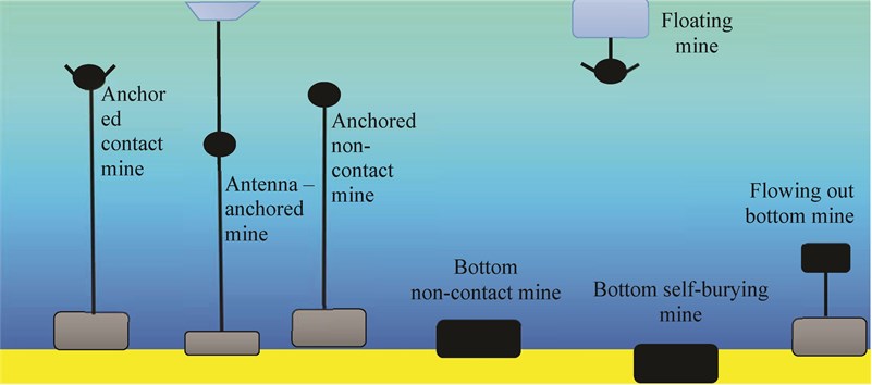
Naval mine is the explosive charge with protective devices, responsive and incendiary placed in the watertight hull used to destruction of the underwater part of the hull of the ship. Among the many divisions and classifications of mines fundamental division concerns the mines places in the water and how it responds to the vessel. Typical classification is shown on Fig. 4, [6].
Fig. 4Classification of naval mines
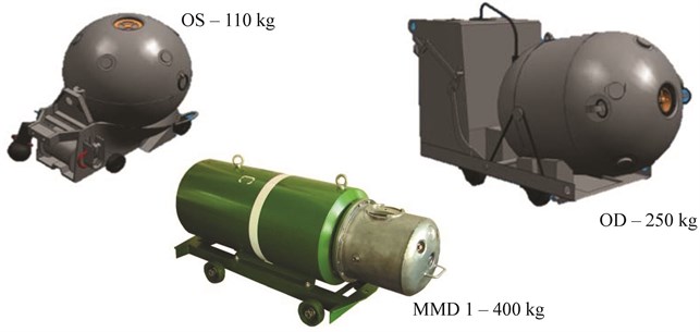
Naval mines were first used in the Crimean War (1853-1856) by the Russian fleet. Modern mines are intelligent devices, capable of movement, and to bury itself in the bottom, which makes them undetectable. They are equipped with various sensors alternating magnetic field, electric potential and improved hydrodynamic field sensors capable of self-regulation depending on external conditions. They can work individually or in groups, acting in an intelligent minefields, able to recognize the enemy ships (IFF system). The Polish Navy uses 4 types of sea mines (Table 2 and Figure 5) with a mass of TNT from 110 to 400 kg. Navies of the world use mine with similar masses, but you can find much larger amounts of up to 1350 kg of TNT. Selected mines are presented in Table 2.
Table 2Polish Navy mines
Name | Depth, m | Mass of TNT, kg |
OD – Okrętowa duża | 12 | 250 |
OS – Okrętowa średnia | 10 | 110 |
MMD – 1 – Mina Morska Denna 1 | 20 | 190 |
MMD – 2 – Mina Morska Denna 2 | 50 | 400 |
Table 3Mines used by other countries Navy [6]
Anchored mines | Bottom mines | ||||||
Country | Name | Depth, m | Mass, kg | Country | Name | Depth, m | Mass, kg |
France | H 30 | 1 – 500 | 300 | France | MCC 23 | 150 | 530 |
Spain | MO-90 | 5 – 340 | 300 | TSM 3530 | 100 | 1000 | |
Germany | DM 11 UMC | 1 – 500 | 40 | Germany | FG 1 | 60 | 535 |
Russia | AMG-1 | 13 – 100 | 262 | DM 61 | 60 | 450 | |
GM | 10 – 200 | 300 | Russia | AMD-1000 | 4 – 200 | 782 | |
KAM | 10 – 40 | 300 | MDM-1 | 12 – 120 | 1120 | ||
KSM | 10 – 210 | 300 | MDM-5 | 8 – 300 | 1350 | ||
Lira | 25 – 250 | 250 | Serpey | 8 – 50 | 750 | ||
M-08 | 6 – 110 | 115 | UDM-2 | - | 800 | ||
M-26 | 6 – 139 | 240 | Sweden | BGM 100 | 5 – 100 | 105 | |
PM-1 | 15 – 25 | 230 | G. Britain | M Mk 2 | 9 – 36 | 462 | |
PM-2 | 45 – 290 | 245 | Sea Urban | 5 – 200 | 600 | ||
Active mobile mines | Stonefish | 10 – 200 | 500 | ||||
Denmark | MTP 19 | 3 – 20 | 300 | Italy | Manta | 2.5 – 100 | 150 – 180 |
Russia | KRM | 40 – 100 | 300 | MN 102 | 5 – 300 | 630 | |
MDS | 4 – 150 | 480 | MR-80 | 5 – 300 | 380 – 865 | ||
SMDM-1 and 2 | 4 – 150 | 480 and 800 | MRP | 6 – 300 | 620 | ||
Fig. 5Polish Navy Mines (Source: Laboratory of Underwater Weapons Polish Naval Academy)
4. Preparation of FEM simulation
The task of explosions, should be regarded as an appropriate task described by the equation of motion. Recognition of this phenomenon using the finite element method requires the use of an appropriate equation in the form:
where: – stiffness matrix; – matrix of inertia (density matrix); – damping matrix, where and are constant coefficients; – displacement, velocity and acceleration vector; – load vector; – strain rate vector; – time; – distance from epicenter; – TNT charge mass.
In the task load vector have been set as a time-varying pressure wave in accordance with equations (1), (2) or (3), (4). Other expressions of equation (5) in this work are omitted, because they describe the structure reaction while this work refers only to load.
Polish Navy is currently using 4 types of sea mines. Among other, uses OS mine which contains 110 kg TNT (Source: Laboratory of Underwater Weapons Polish Naval Academy). The paper examined a case in which such a charge detonates around the ship of Kormoran II project. Using CAD programs reflected outer shell of the ship, and then implements it into CAE program in which the relevant calculations were carried out.
Due to the very short load time very high attention should be paid to the finite element size and time step choice. The calculations of explosions are complex and lengthy because of fact that for large structures character of the load can be omitted. To compare waveforms pressure from analytical solutions or experiments the relationship can used:
where: – time of the first positive pulse pressure wave, s; – hydrostatic pressure, Pa.
As is apparent from Fig. 6 the individual waveforms can be close to each other but maximum can be undercut. Due to the fact that in the present time step, one of the nodes has been dispensed with a lack of symmetry of the load has been shown. Properly selected time step and the size of the element shown in Fig. 7.
Fig. 6An example of incorrect element size and time step [5]
![An example of incorrect element size and time step [5]](https://static-01.extrica.com/articles/15746/15746-img6.jpg)
Fig. 7Proper time step and element size [5]
![Proper time step and element size [5]](https://static-01.extrica.com/articles/15746/15746-img7.jpg)
Charge was placed at a distance of 9 m below the keel of the ship. According to equation (3) the pressure on the front of the shock wave is 25.67 MPa. The pressure calculated by the program was 29 MPa. The difference results from the strong relationship between the size and shape of mesh elements. In the paper [5] the effect of mesh size and shape on the propagation of the shock wave were analyzed. It was found that the 4 - nodal tetragonal of size of 0.5 m elements are best to use.
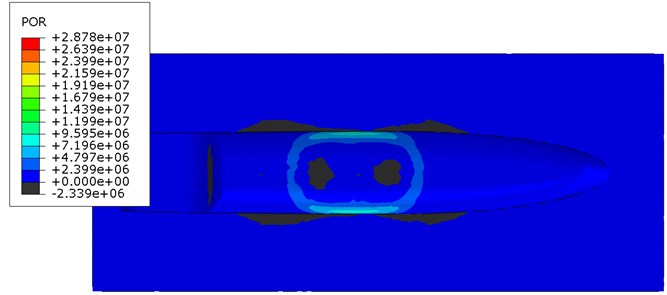
The pressure distribution of non-contact mine explosion in the acoustic medium in different time points were shown. The pressure wave reaches the ship's hull and it is reflected resulting in a negative pressure. The decrease of pressure can lead to cavitation under the keel of the ship. In this case, if the ship is treated as a beam supported continuously, due to cavitation a discontinuity of the support will appear and the ship would be load with the forces of gravity. In this work, this phenomenon is omitted.
Fig. 8Pressure distribution of non-contact TNT explosion under the keel of the ship
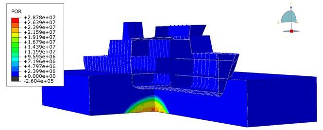
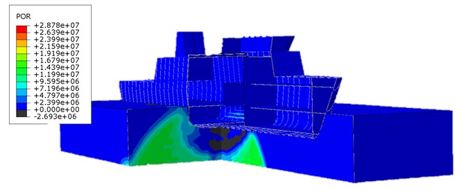
Fig. 9Pressure distribution of non-contact TNT explosion under wet surface of the ship
5. Conclusions
Study describes the phenomenon of underwater explosion. The model used in the study is the latest model of the shock wave in this type calculations. Problems that results from the application of the acoustic medium and its response for the given load. Also highlights the FEM equation that describes the dynamics task. The complexity of this task depends on the author and expected results. In case of underwater explosions weight loss, elements self – contact or hardening of the material due to the strain rate can be included. The influence of various parameters on the results will be examined in further publications.
Using the presented method of modeling underwater explosion can also designate an approximate movement parameters for the foundations of the devices inside the ship. Omitting the effect of cavitation and other phenomena can have a significant impact on the response of the structure. However, is assumed, that for steel the most important is a first shock wave, which is described in this article.
It should also be used carefully presented equivalents of TNT. A multitude of methods for their determination as well as errors due to incorrect modeling of acoustic mesh elements can significantly affect the obtained results.
References
-
http://www.remontowa-rsb.pl/kormoran_ii/
-
Jeremić Radun, Bajić Zoran An approach to determining the TNT equivalent of high explosives. Scientific-Technical Review, Vol. 56, Issue 1, 2006.
-
Cudny K., Powierża Z. Selected problems of ships impact resistance. Polish Naval Academy, Gdynia, 1978, (in Polish).
-
Grządziela A. Model of impact underwater detonation. Journal of Kones, Vol. 18, Issue 2, 2011, p. 145-152.
-
Kiciński R. Simulation of deformation of a hull of a submarine from non-contact sea mine explosion. Polish Naval Academy, Gdynia, 2014, (in Polish).
-
Kuliś Frankowski Sea mines (1945-1998). Polish Naval Academy, Gdynia, 1999, (in Polish).
-
Kiciński R. Determination of pressure distribution of non-contact TNT explosion on the hull of the Kobben class submarine. Polish Naval Academy, Gdynia, 2013, (in Polish).
-
Cole R. H. Underwater Explosions. Princeton University Press, Princeton, 1948.
-
Geers T. L., Hunter K. S. An Integrated Wave-Effects Model for an Underwater Explosion Bubble. Boulder, 2002.
-
Reid W. D. The Response of Surface Ships to Underwater Explosions. Defence Science and Technology Organisation, Melbourne, 1996.
-
Stiepanow W. C., Sipilin P. M., Nawagin J. S., Pankratow W. P. Blast punching. Scientific-Technical Publications, Warszawa, 1968.
-
Didoszak J. M. Parametric Studies of DDG-81 Ship Shock Trial Simulations. Monterey, 2004.
-
Brown A., Klenow B. Far-Field Underwater Explosion (UNDEX) Fluid Modeling using Acoustic Elements. http://www.aoe.vt.edu/people/webpages/albrown5/papers/pressureelementssaviac2007.pdf
-
Aman Z., Weixing Z., Shiping W., Linhan F. Dynamic response of the non-contact underwater explosions on naval equipment. Marine Structures, Vol. 24, Issue 4, 2011, p. 396-411.
-
Aruk F., Mugan A., Toprak T. Finite element analysis of response of a floating structure to an underwater explosion. Turkey Abaqus Users’ Conference, Istambul, 2014.
About this article
