Abstract
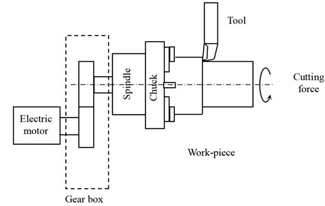
Bearing and gear are one of the most important mechanical sources for vibration and noise generation in machine tool spindles. In this paper, we study the non-linear dynamic behavior of a machine tool spindle system in transient regime. Driving and driver rotors are, respectively, powered by a motor torque and loaded by the cutting force. They are supported by two identical Rolling Bearings (RBs). Gear excitation is induced by the motor torque and load variation in addition to the fluctuation of meshing stiffness due to the variation of input rotational speed. The dynamic parameters of RBs are modeled by stiffness and damping matrices computed by the derivation of the bearing forces. The equations of motion are solved iteratively using Newmark time integration method. The numerical results of the dynamic responses of the system come to confirm the significant effect of the transient regime on the dynamic behavior of a gear set.
1. Introduction
Bearings play an important role in machine tool spindle systems. Compared with hydrostatic, aerostatic or magnetic bearings [1], rolling element bearings are still most commonly used today in the spindles, which can provide the required precision, load carrying capacity, and spindle speeds. The dynamic behavior from the transient state chaotic motion to the steady state periodic and quasi periodic motions is also established by Zhang et al. [2]. Luisa et al. [3] reveal how to take advantage of the information on vibrations from the mechanical system in a varied range of speed and load conditions. Acceleration signals from the accelerometers are treated using a new formulation to study the gear motions. In the developed concept of supports for aviation purposes, some simulations have been performed. A necessity of increasing bearings load capacity and damping has occurred by Kozanecka et al. [4].
In rotating machine, to provide speed and torque conversions from a rotating power source to connected mechanical devices, gear reducers are often used but its represent a principal source of vibration and noise due to excitations associated with the conditions of contact between gear pair teeth. Kang et al. [5] made an experimental results specify that the proposed accelerometer-based measurement methodology is operational in measuring not only the torsional motions but also the other types of translational, rotational and axial motions of a gear. To study the dynamic behavior of a spur gear pair it is required to define the stiffness in the contact zone named gear mesh stiffness. The gear set have internal and external sources of excitations. The internal one is made by the time varying mesh stiffness. These fluctuations are considered the main source of system excitation and the origin of the observed noise and vibrations [6]. Bartelmus [7-8] presented the varying mesh stiffness in dynamic model of a spur gear system to investigate the different responses in presence of defects. Chaari et al. [9-10] introduced the varying mesh stiffness in a dynamic model of a spur gear system in order to study its dynamic responses in presence of defects. Added frequency components were observed in response spectra. Sachidananda et al. [11] presented analytical and experimental methods to investigate and compare the altered tooth sum gearing against the standard tooth-sum gearing. The experiments were performed using a power recirculating type test rig. The tooth loads for the experimental investigations were determined considering the surface durability of gears.
Bartelmus [7-8] and Walha et al. [12] studied the effect of backlash on the dynamic behavior of a two stage gearbox. They concluded that tooth separation occurs at the transient regime with increase in the vibration level. Sika and Velex [13, 14] proposed a model to study, in transient regime, the influence of gear tooth geometry, the backlash and the backstrike effect on the dynamic behavior of gear system. A gear set powered by an electric motor in the start time was also investigated by Hugues [15]. He noticed that the existence of distributed faults induces an increase in the vibration levels when load increases.
2. Model of a single stage spur gear reducer
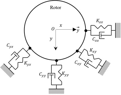
A single stage spur gear model with eight degrees of freedom is presented in Figs. 1 and 2. It is composed by two rotors supported by RBs. The driving rotor (Part 1: P1) has a pinion with teeth, mass and moment of inertia . The driven rotor (Part 2: P2) has a wheel with teeth, mass and moment of inertia .
Fig. 1Modeling of a single stage spurs gear
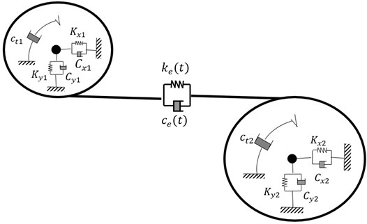
The system is sought by motor torque and load torque . The gear mesh stiffness and damping are modelled by linear spring and damping acting on the line of meshing teeth action (Fig. 3). The displacement along the line of action is expressed by [16]:
where and are the translation of the pair of gear ( 1, 2). is the angular displacement of the component in part (, 1, 2), is the pressure angle, and are, respectively, the base radius of the pinion and the wheel, is the rotational speed of the pinion.
The mesh period can be defined by:
The vector of the degrees of freedom can be expressed by:
Fig. 2Modeling of a single stage spurs gear
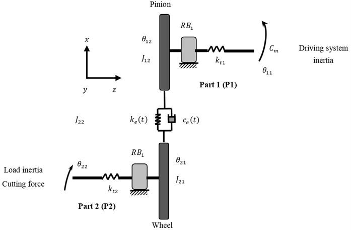
Fig. 3Meshing modeling
3. Derivation of the equations of motion
3.1. Rolling bearing modeling
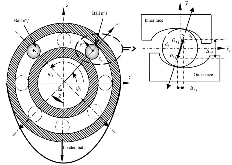
The forces and moments, exerted by the th rolling bearing supporting the spindle (Fig. 4), are defined, and using the Hertz contact theory, as:
where, and represents respectively the ball angular position and the loaded contact angle, presents the radial position of the outer race curvature centre of the th ball, represents the Hertz contact constant, deduced from curvature radius of the elements in contact, and represents the elastic deformations of the th ball.
This last is defined as follows:
where, and present respectively the radial and axial deflections. They are expressed in the reference , functioning of the elastic and rigid movements of the th node of the spindle:
Fig. 4Modelling of Rolling Bearing (RB)
The new loaded contact angle can be deduced:
The scaling default is modeled by a half sine wave introduced at the th ball deflections expressions, which will be:
In the present study the classic linearised model with four stiffness and damping coefficients is used for the RBs modeling. In this model presented in Fig. 5, the forces at each bearing are assumed to obey the governing equations of the following form [17]:
where and are the RBs degrees of freedom, and are respectively the RBs stiffness and damping matrices. They are expressed by:
The derived equations of motion can be represented in a matrix-vector form. It can be written as:
where, represents the mass matrix given by:
includes the RBs stiffness (,,), the shaft torsional stiffness , and the time varying gear mesh stiffness . It is expressed by:
includes the RBs damping (, , ), the shaft torsional damping , and the time varying gear mesh damping . It is expressed by:
is the external applied torques vector. It can be expressed as:
Fig. 5Two dof RB model
3.2. Cutting model
The cutting model used in this paper is the dressing and roughing operations. Tangential and normal cutting forces are respectively given by:
with and are terms which reflect the specific cutting pressure, is the width of cut, is the instantaneous cutting thickness.
3.3. Electric motor modeling
The rotational velocity of an electric motor can be related to its torque and the receiver torque by:
where is the equivalent moment of inertia of the rotating parts.
The relation between driving torque and the motor speed have the following form [18]:
where is the slip, is the torque at breakdown, and are two constants characteristic of the motor and is the proportional drop in speed given by:
where and are, respectively, the synchronous speed and the actual rotational speed of the motor.
In the present study a pump is chosen as a load. Load torque characteristic is proportional to the square of the rotational speed [19]:
where is a coefficient depending on the driven system kind. Eq. (17) can be written as follows:
4. Numerical simulations
Using Newmark integration method, the dynamic behavior of spur gear system is studied by a numerical simulation. The mechanical system is powered by an electric motor. The principal characteristic parameters of the electric motor are given in Table 1. The principal parameters of the spur gear transmission are given in Table 2. Tables 3 presents the eigenfrequencies of the system.
Table 1Parameters motors specifications
Electric motor type: ABB-MT 90L | |
Electric characteristics 4 poles, 50 Hz, 3 phases | 415 V |
Power (kW) | 1.5 |
Nominal speed (rpm) | 1440 |
Nominal torque (N m) | 10 |
Ratio of starting up torque | 2.7 |
Ratio of breakdown torque | 3.2 |
Slip | 0.315 |
Constant of the motor (a) | 1.711 |
Constant of the motor (b) | 1.316 |
Table 2Characteristic parameters of the spur gear
Pinion | Wheel | |
Teeth numbers | 20 | 40 |
Mass (Kg) | 0.6 | 2.5 |
Inertia moment (Kg·m2) | 2.6 10-4 | 45 10-4 |
Base circle (m) | 0.05 | 0.11 |
Module (mm) | 3 | |
Rotor torsional stiffness (N·rd/m) | 105 | |
Pressure angle (°) | 20 | |
Teeth width (mm) | 23 | |
Contact ratio | 1.6 | |
Table 3The determinate eigenfrequencies of the system
Eigen frequencies (Hz) | |||||||
0 | 730,5 | 904,3 | 1278,3 | 1424,4 | 1891,5 | 2925,6 | 3481 |
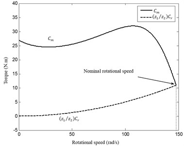
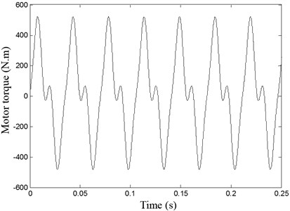
The mechanical transmission is loaded by a machine tool having an inertia moment 45×10-4 Kg·m2. Using the Euler algorithm to resolve Eq. (11), the evolution of motor rotational speed versus time is presented in Fig. 6. Two different regimes are determinate. The first is the transient regime observed in the time interval [0, ], characterized by an increasing rotational speed. The second regime is the steady state observed in a time greater than and subsequently the motor reaches its nominal rotational speed . The transient regime duration is 0.185 s. The evolution of motor and receiver torques of the studying system is shown in Fig. 7.
Fig. 6Evolution of torque vs time
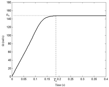
Fig. 7Mechanical characteristics of the driving and driven systems
The evolution of the meshing stiffness in transient regime is shown in Fig. 8; numerical results show that it is modeled as a non-periodic function. It should be noted that the meshing period decreases when the speed increases.
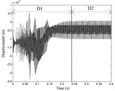
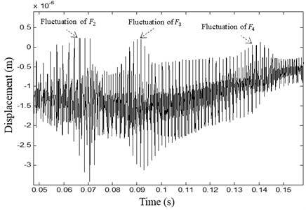
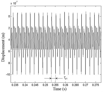
The dynamic response registered on the pinion is presented in Fig. 9(a). Two different behaviors are determinate: The first period () corresponding to the interval of time [0, ] in which the displacement is variable and non-periodic with high vibration amplitudes (Fig. 9(b)). The second period () is observed in time interval [, ] in which the displacement is periodic with period (Fig. 9(c)). The motor rotates at its constant nominal frequency and the meshing stiffness is periodic with a constant period. The dynamic response shows periodic behavior with steady vibration level.
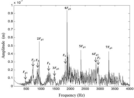
The displacement is non-periodic during the transient regime, who explains that the corresponding spectrum is rich frequency content. The frequency spectrum of the linear displacement of the pinion shaft is presented in Fig. 10. The spectrum indicate the presence of the meshing frequency 480 Hz and its harmonics × encircled by side-bands. The system eigenfrequencies and are also shown. The presence of side-bands is caused by the transient regime behavior.
Fig. 8Non-periodic evolution of the meshing stiffness in transient regime
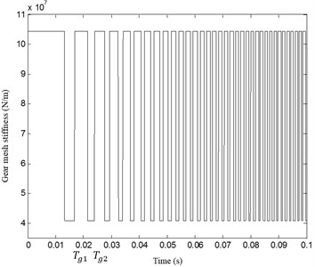
Fig. 9a) Pinion RB1 displacement, b) non stationary domain D1, c) steady state domain D2
a)
b)
c)
The high amplitude values of displacement in the transient response are the direct result of the torsional vibration problem caused by the fact that torsional and lateral movements are coupled via the gear mesh [19].
Fig. 10Spectrum of pinion RB1 displacement
To investigate the effect of transient regime on the gear teeth, the inter mesh forces and the transmission error are studied.
Fig. 11 presents the transmission error evolution. It’s illustrate that error is time varying and periodic with as the period and its fluctuation is depend of loading conditions.
Fig. 11Error transmission evolution vs time
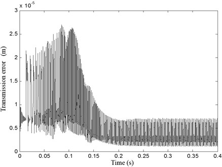
Fig. 12 indicates the normal evolution of the effort on teeth according to time. It shows that cyclic over loads on teeth can be expected with values reaching 33.104 N.
Fig. 12Evolution in time of the torque applied on the transmission spur gear
5. Conclusions
In this study, the dynamic response of a machine tool system is analyzed in the transient regimes. The variations of input rotational speed are studied. As a consequence of the speed variation, the gear mesh stiffness was modeled with varying period to take into account transient regimes. The torque developed by the electric motor is expressed as a function of the angular position of the crankshaft. The gear mesh stiffness was adequately computed and introduced in the equations of motion of the system and then a numerical simulation was conducted. The numerical results of the dynamic responses of the mechanical system come to confirm a significant effect of the transient regime on the dynamic behavior of a gear set.
References
-
Inayat-Hussain J. I. Geometric coupling effect on the bifurcations of a flexible rotor response in active magnetic bearings. Chaos, Solitons and Fractals, Vol. 41, Issue 5, 2009, p. 2664-2671.
-
Zhang Wei, Zu Jean W. Transient and steady nonlinear responses for a rotor-active magnetic bearings system with time-varying stiffness. Chaos, Solitons and Fractals, Vol. 38, 2008, p. 1152-1167.
-
Villa Luisa F., Renones Anıbal, Peran Jose R., de Miguel Luis J. Statistical fault diagnosis based on vibration analysis for gear test-bench under non-stationary conditions of speed and load. Mechanical Systems and Signal Processing, Vol. 29, 2012, p. 436-446.
-
Kozanecka D., Kozanecki Z., Łagodzin J. Active magnetic damper in a power transmission system. Communications in Nonlinear Science and Numerical Simulation, Vol. 16, 2011, p. 2273-2278.
-
Kang Ma Ru, Kahraman Ahmet Measurement of vibratory motions of gears supported by compliant shafts. Mechanical Systems and Signal Processing, Vol. 29, 2012, p. 391-403.
-
Chaari F., Fakhfakh T., Haddar M. Analytical modelling of spur gear tooth crack and influence on gearmesh stiffness. European Journal of Mechanics – A/Solids, Vol. 28, 2009, p. 461-468.
-
Bartelmus W. Mathematical modelling of gearbox vibration for fault diagnosis. International Journal of COMADEM, Vol. 3, 2000, p. 5-15.
-
Bartelmus W. Mathematical modelling and computer simulations as an aid to gear box diagnostics. Mechanical Systems and Signal Processing, Vol. 15, 2001, p. 855-871.
-
Chaari F., Baccar W., Abbes M. S., Haddar M. Effect of spalling or tooth breakage on gear mesh stiffness and dynamic response of a one-stage spur gear transmission. European Journal of Mechanics – A/Solids, Vol. 27, 2008, p. 691-705.
-
Chaari F., Fakhfakh T., Hbaieb R., Louati J., Haddar M. Influence of manufacturing errors on the dynamic behavior of planetary gears. International Journal of Advanced Manufacturing Technology, Vol. 27, 2006, p. 738-746.
-
Sachidananda H. K., Gonsalvis Joseph, Prakash H. R. Experimental investigation of fatigue behavior of spur gear in altered tooth-sum gearing. Frontiers of Mechanical Engineering, Vol. 7, Issue 3, 2012, p. 268-278.
-
Walha L., Fakhfakh T., Haddar M. Nonlinear dynamics of a two-stage gear system with mesh stiffness fluctuation, bearing flexibility and backlash. Mechanism and Machine Theory – Journal, Vol. 44, 2009, p. 1058-1069.
-
Sika G., Velex P. Analytical and numerical analysis of gears in the presence of engine acyclism. Proceeding of the 10th ASME International Power Transmission and Gearing Conference, Las Vegas, 2007.
-
Sika G., Velex P. Analytical and numerical analysis of gears in the presence of engine acyclism. Journal of Mechanical Design, Vol. 130, 2008, p. 1-6.
-
Hugues J. G. Contribution to the Dynamic Study, During Startup, of Drivelines Gear Driven By Electric Motors. Ph.D., INSA Lyon, France, 1993, p. 193.
-
Velex P., Ajmi M. Dynamic tooth loads and quasi-static transmission errors in helical gears – approximate dynamic factor formulae. Mechanism and Machine Theory, Vol. 42, Issue 11, 2007, p. 1512-1526.
-
Bouaziz Slim, Hili Molka Attia, Maatar Mohamed, Fakhfakh Tahar, Haddar Mohamed Dynamic behaviour of hydrodynamic journal bearings in presence of rotor spatial angular misalignment. Mechanism and Machine Theory, Vol. 44, 2009, p. 1548-1559.
-
Wright D. Class Notes on Design and Analysis of Machine Elements. Department of Mechanical and Materials Engineering, The University of Western Australia, 2005.
-
Khabou M. T., Bouchaala N., Chaari F., Fakhfakh T., Haddar M. Study of a spur gear dynamic behavior in transient regime. Mechanical Systems and Signal Processing, Vol. 25, 2011, p. 3089-3101.
About this article
