Abstract
The purpose of the present study is to improve the conventional electrodynamic shaker’s performance at low frequency through the optimization of its support spring. It is acknowledged that to improve its low frequency performance, a shaker’s support spring has to be lightweight and simultaneously of high lateral but low axial rigidity. Meanwhile it should have few resonance points in the useable frequency range. But both experimental modal analysis (EMA) and finite element analysis (FEA) in this study indicated that of the support spring of conventional shaker presents undesirable humps in its frequency response (FR) in low frequency area. The first order resonance frequency of the shaker (whose value decides the minimum of the shaker’s useable frequency range) also turned out big. Hence a new support spring plate of laminated composite structure embedded with viscoelastic damping material is proposed in this study whose parameter values are further optimized. The optimization adopts damping thickness, angle and thickness of composite layer as the design variables. It targets at achieving minimum weight while satisfying the shaker’s first order elastic natural frequency and the plate’s intensity. The optimized support spring plate is then put to frequency response analyses. The findings indicate that it not only can suppress the humps in low frequency area, but also widens the shaker’s useable low frequency range. Meanwhile it reduces the shaker’s additional rigidity on the test object. Hence it can ensure the shaker’s performance at low frequency.
1. Introduction
Electrodynamic shakers have been widely utilized in scientific researches and tests because of their small size, high precision, long duration and comparatively low cost. They mainly consist of a magnet structure, moving element (armature, thrust axis), the support spring and shell. The moving element and support spring form the moving system whose dynamic property determines a shaker’s frequency characteristics. The support spring alone decides its low frequency characteristics [1, 2].
The support spring has two functions: to support the moving elements to move axially and to circumferentially fix coils in the center of the magnetic field gap [3]. Thence it has to be simultaneously of high lateral rigidity and small axial rigidity. Meanwhile it should have few resonance points in the useable frequency range. At the same time, it has to be lightweight to reduce the additional mass loading of the shaker on the test object. To ensure the shaker’s performance at low frequency, previous researches attempted to improve the support structure by adopting air bearings in place of flexible hanging, using non-linear metal spring or damping materials [4-8]. But none of them can work out a support spring that meets all the requirements at once. In practice, the conventional E shaker still presents undesirable humps in its FR, which affect the accuracy of test results of low frequency vibration tests [9].
The goal of this study is to improve the performance of conventional shaker at low frequency by optimizing its support spring. Its starts with a thorough study on the causes of humps in the shaker’s FR by adopting experimental and numerical research methods. It accordingly proposes a new laminated composite structure with viscoelastic damping material for the spring plate. Finally the proposed support spring plate is further optimized.
2. Low frequency performance of conventional E shaker
2.1. FR experimental measurement of the shaker
To study the low frequency performance of conventional E shaker, this study has carried out an experiment on an unloaded E shaker to measure its frequency response functions (FRF). The experiment system is shown in Fig. 1, including: power amplifier, Hp-35670 dynamic signal analyzer, accelerometer and E shaker.
In the experiment, the accelerometer was mounted to the table of the thrust axis and the power amplifier working method was set at the constant flow to maintain the constant force output from the armature. The experiment employed swept sine excitation at frequency 5-2500 Hz.
Fig. 1Block diagram of the testing system
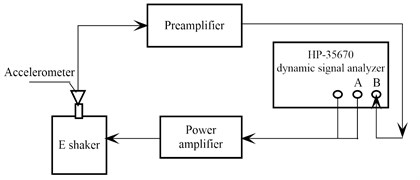
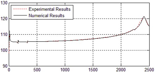
Fig. 2 presents the FRF experimental results of E shaker with the table bare. As shown in Fig. 2(a), the FR curve in the useable frequency range demonstrates that the two peaks are consistent to the previous theory analysis [10]. The two points of resonance corresponding represent the first and second order natural frequency of the shaker’s moving system respectively. In other words, they indicate the minimum value and maximum value of the shaker’s useable frequency range. As shown in Fig. 2(b), the shaker produced first order resonance at 13.74 Hz. So its minimum useable frequency is 20 Hz. Within the shaker’s useable low frequency range, the FR curve displays obvious humps at 162.24 Hz and 341.94 Hz which are undesirable in broadband vibration test of high-precision.
Fig. 2FRF experimental results of the unloaded E shaker in EMA
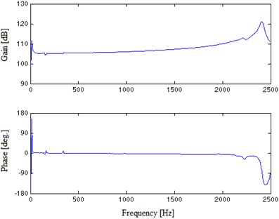
a) In useable frequency range
b) In low frequency area
2.2. Mode measurement of support spring plate
Previous researchers have identified that the humps in low frequency area are caused by the elastic resonance of support spring plate [11]. To verify this idea, vibration modes of the spring plate at the undesirable hump points were measured to compare with the FEA results. The testing system was consistent to that of FR measurement of the shaker with the accelerometer mounted on the support spring plate. The power amplifier was set at the constant flow. The FRFs at various measuring points were measured at 5 Hz-2500 Hz. To obtain constant exciting force, the output current of power amplifier maintained invariable.
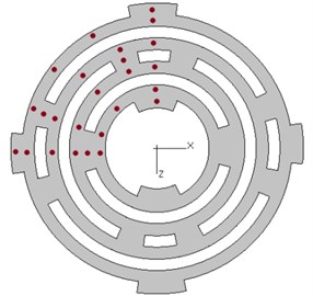
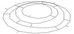
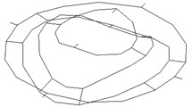
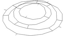
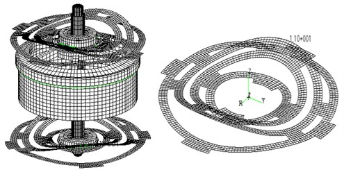
For small and medium sized symmetrical structure, the vibration mode of the whole structure can be obtained through the geometric mapping and direct order expansion of the symmetrical region modes to other regions during the modal test [12]. Since the spring plate was axially symmetrical, for the convenience of research, only one-fourth of the spring plate was measured. To build experimental modal shape out of the experimental data, measuring points should be identical to nodes corresponding to the finite element model (FEM) and evenly distributed over the entire test area. Section lines should be shunned. Fig. 3(a) shows the location of total 25 measuring points, on the basis of which, the FEM of the EMA was constructed as shown in Fig. 3(b).
Fig. 3EMA of the spring plate
a) Measuring points on the spring plate
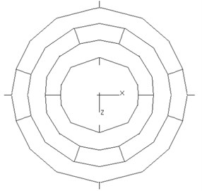
b) FEM of EMA
Fig. 4 displays the vibration modes of hump points on the spring plate respectively. Fig. 4(a) is the mode shape of spring plate vibration at the first order frequency. Here the moving system is simplified to have single degree of freedom. Judging from the figure, there is no resonance produced. Fig. 4(b) and Fig. 4(c) are the vibration mode shapes of the spring plate at 162.24 Hz and 341.94 Hz. Since the shaker still works in low frequency region, the moving system can be considered rigid. So the resonance occurred at 162.24 Hz and 341.94 Hz is caused by elastic resonance of the spring plate itself.
Fig. 4Mode shapes of spring plate vibration
a) 13.74 Hz
b) 162.24 Hz
c) 341.94 Hz
2.3. FEM of the shaker
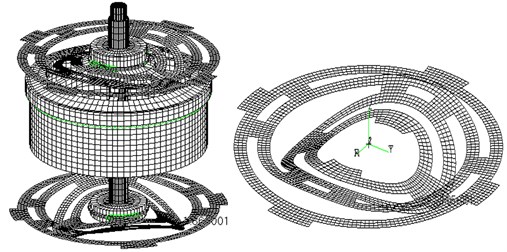
The E shaker is single armature structured whose moving system is comprised of the upper and lower support spring plates and moving element. The support spring plate itself is fixed on the shell. The mounted pattern of the shaker is determined by work frequency. It can be rigid fixed, elastic fixed or elastically fixed on the test object. The purpose of all three mounting patterns is to keep the shell of shaker still [13, 14]. Since the shell is static at work, only the FEM of moving system was established in this numerical simulation and the six freedom degrees of jointing support spring plate boundary were restrained.
Fig. 5FEM of the moving system of E shaker
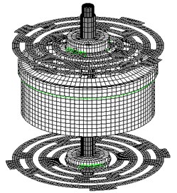
Fig. 5 is the FEM of E shaker’s moving system. For calculation precision, this study adopted 8-node 6 sided elements for moving element modeling simulation (excepting coil). Otherwise it adopted 6-node 5 sided elements to meet the requirements of the geometry shape. Considering the support spring plate and coil are relatively thin, this study adopted 4-node quadrilateral shell elements for their modeling simulation. Shell elements and body elements were connected by multiple point constraint (MPC). The thrust axis was made of carbon steel 1Cr18Ni9Ti. The skeleton used hard aluminum-alloy LyCZ12. The support spring plate adopted rubberized cloth board while the coil was made of QZ-2 high-strength enamel-insulated wire. The specific parameters are in Table 1.
Table 1Material parameters
Material name | Elasticity coefficient (N/mm2) | Poisson’s ratio | Density (kg/mm3) |
1Cr18Ni9Ti | 1.98×10⁸ | 0.3 | 7.9×10⁻⁶ |
LyCZ12 | 7.0×10⁷ | 0.31 | 2.78×10⁻⁶ |
Rubberized cloth board | 6.56×10⁶ | 0.34 | 1.35×10⁻⁶ |
Enamel-insulated wire | 1.08×10⁸ | 0.33 | 8.4×10⁻⁶ |
With the modal frequency response analytic method, axial force changing with frequency within 5 Hz-2500 Hz was exerted on the armature. Eigenvalue was computed with Lanczos solution which can guarantee no root loss in large structure eigenvalue solution process. Hence it maintained the integrity of dynamic characteristics of FEA. Modal damp The combination of FREQ1 and FREQ4 in Nastran within 5 Hz-2500 Hz was used to define and analyze length of frequency step to ensure at least 5 computation points in each half of the band width.
Fig. 6 shows FRF numerical results of E shaker with the table bare. Fig. 7 presents vibration modes of E shaker and its moving system at hump points of 13.761 Hz, 167.24 Hz and 331.97 Hz respectively. The frequency values and corresponding modes of resonant points in the FR are shown in Table 2. They demonstrate FEA results are consistent with EMA results and theoretical analyses results. The moving system produces the first order resonance at 13.76 Hz due to fact that the rigidity of moving element is considerably larger than that of the support spring, so the moving element is actually a unidirectional vibrating system whose first order natural frequency (the minimum value of the shaker’s useable frequency range) is decided by the rigidity of the support spring. The comparison of EMA and FEA at 167.24 Hz and 331.97 Hz where the humps appear proves that they are caused by the elastic resonance of the spring plate.
Fig. 6FRF numerical results of the unloaded E shaker
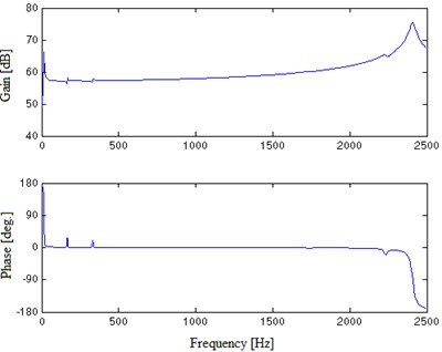
a) In useable frequency range
b) In low frequency area
Fig. 7Vibration modes of E shaker and moving system
a) 13.761 Hz
b) 167.24 Hz
c) 331.97 Hz
Table 3 and Fig. 8 give the comparison of experimental and numerical results. As seen from the table, with a relative error lower than 5 %, the experimental value and the predicted value of main natural frequency can verify the accuracy of each other. They also show the FEM of the moving system has authentically simulated the shaker’s dynamic property and it is reliable to provide valid data for further dynamic design of the shaker. Fig. 8 demonstrates the experimental results are consistent with the simulation results.
Table 2Frequency value and corresponding mode of hump points in FR
Frequency value (Hz) | Description of mode | Mode | |
1 | 13.76 | Moving system first-order resonance | Fig. 7(a) |
2 | 167.24 | Spring plate axial first-order resonance | Fig. 7(b) |
3 | 331.97 | Spring plate axial second-order resonance | Fig. 7(c) |
Table 3Comparison of experimental results and numerical results
FEA (Hz) | EMA (Hz) | Relative error | |
1 | 13.76 | 13.74 | 0.15 % |
2 | 167.24 | 162.24 | 3.08 % |
3 | 331.97 | 341.94 | 2.92 % |
Fig. 8Comparison of FRF experimental results and numerical results
a) In useable frequency range
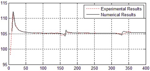
b) In low frequency area
3. Spring plate of laminated composite structure with viscoelastic damping material
The elastic vibration of the support spring plate itself leads to humps in the shaker’s FR in the useable low frequency area. Despite of their small value of amplitude, these humps have noticeable effect in broadband vibration experiment of high accuracy or in vibracutting. One solution is to embed viscoelastic damping material to offset the elastic vibration of the spring plate.
Additional damping materials structure is divided into two categories as in Fig. 9. The first is referred to as the free-layer damping. In this case, whenever the structure is subjected to flex, the damping material will be subjected to tension-compression deformation to consume vibration energy. The second one is called constrained-layer damping. When the damping layer flexes with the structure, because the damping material is constrained by another layer, it deforms in shear to produce damping dissipation energy. For a given weight, the latter is more efficient. However, its efficiency is balanced by greater complication in analysis and application. In the free-layer damping, the position of the damping layer remarkably affects the damping efficiency, apart from the direct influence of properties of damping material and thickness of the damping layer on the composite construction’s loss factor [15]. When the damping layer is thin or there is no noticeable difference between the thickness of the damping layer, beam and plate, the viscoelastic damping material is embedded in one side of the structure to achieve the highest damping effectiveness.
Fig. 9Additional damping materials structure

a) Free-layer damping
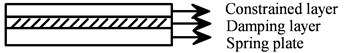
b) Constrained-layer damping
Viscoelastic damping is the most common damping mechanism at present. It dynamic property mainly refers to the real part of complex modulus (or the real part of complex shear elasticity ) and the material loss factor (which is generally defined as the ratio of the imaginary part to the real part of the complex modulus). A great amount of researches and tests have proved that and are sensitive to the surroundings, especially temperature, frequency and strain amplitude [16]. The viscoelastic damping material on the support spring plate is mainly affected by frequency. Due to its low cost and simplicity in application, the free-layer damping is adopted in this study. The viscoelastic damping material is ZN-1 with , 1250 kg/m3, .
4. Support spring plate optimization
4.1. Problem description
The above analysis shows the elastic resonance of the support spring plate leads to undesirable humps in the shaker’s FR in the low frequency area. Therefore, to broaden the shaker’s useable low frequency range, improve its low frequency performance, at the same time effectively inhibit or eliminate the effects of elastic resonance, optimum dynamic design shall be carried to the support spring plate.
The support spring plate of E shaker is hollow structured, featuring high lateral rigidity but low axial rigidity. Moving system comprised of spring plate of this structure style has significantly lower first resonant frequency. On the other hand, composites have many merits such as high tenacity, big modulus-to-density ratio, good fatigue resistance and good aseismic performance [17]. So on the basis of primary structure, this study adopts laminated composite structure with viscoelastic damping material for the support spring plate. Then it carries on optimum dynamic design with the damping thickness, angle and thickness of composite layer as the design variables, lightest weight as the objective function and intensity of support spring plate and the first-order resonant frequency of moving system as constraints.
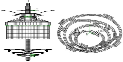
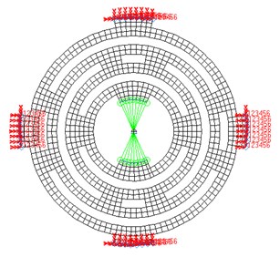
The optimum design of spring plates can be carried on only one since the upper and lower support spring plates of the shaker are identical and paralleled connected. Comparatively the optimum design of moving system is complex. Though there are many resonance points in the useable low frequency range, only axial elastic resonance caused by support spring plates sways obvious effect in the shaker’s FR. Therefore this study simplifies the moving element to one mass point whose value is half of the moving element. This mass point connects to the spring plate under multi-point restrictions (the MPC unit). To avoid interior boundary deformation in the process of simulation, beams of high rigidity are added to the interior boundary of spring plate. Fig. 10 is the equivalent FEM for optimum dynamic design. Green colored parts are MPC unit while parts colored in red indicate the boundary constraints of support spring plate.
As a result of the spring plate shape rule, quadrangle shell element is adopted. The spring plate is finite element meshed into 1171 nodes, one quality unit (conm2), 869 quadrilateral elements, 1 MPC unit (Rigid). The six freedom degrees of the jointing support spring plate boundary shall be restrained in the same way.
In the optimization, two subcases are defined for computing the weight and element stress of structure and the first resonant frequency of structure respectively.
Fig. 10Equivalent FEM for optimum dynamic design
4.2. Establishment of optimum model
4.2.1. Objective function and design variables
The purpose of the optimum dynamic design is to obtain lower first resonant frequency and achieve the lightest spring plate weight while maintaining its intensity. Therefore lightest structure weight is taken as the objective function of the optimum design.
That is:
where is the mass of the shake’s moving system.
The support spring plate is a symmetrical laminated composite structure with viscoelastic damping material embedded in the surface. In the optimization process, 7 design variables are selected, including damping thickness, angle and thickness of composite layer.
They are:
Among which are the thickness and angle of composite layer respectively ( 1, 2, 3). is the damping thickness.
4.2.2. Constraints
1. Performance constraints.
Performance constraints are two: one is the first-order resonant frequency of the structure is less than 5 Hz; the other is that design stress of support spring plate shall be less than the allowable stress of the material. According to Tsai-Hill (Tsai-Hill) strength criterion, stress ratio of any layer of any cell shall not be less than 1 in layer thickness adjustment.
2. Size constraints.
Size constraints refer to upper and lower bound constraints of the design variables. The thickness of composite layer and damping thickness are 5 mm at maximum and 0.01 mm at minimum. The upper limit of layer angle is 90 degree.
4.3. Optimization results and analysis
On the platform of MSC/Nastran, using several techniques including coupling design variable linking, constraint screening and sensitivity analysis [18-22], this study first has built an approximate model, which adopted zero-order approximation to turn stress constraints to a dynamic minimum size, first-order approximation in natural frequency constraints. To avoid the relatively large size of the model caused by too many variables, this study rendered the original model into a dual one, then obtained a standard quadratic programming model by objective function quadratic and reached the iterative solution of the original model.
As shown in the course chart in Fig. 11, after 18 optimizing design cycles, objective function converges to the optimal solution, in which the first order natural frequency of the moving system reaches the desired target value of 5 Hz under the constraint conditions. The optimized support spring plate weighs 18.86 g, 31.17 % less than the initial 27.4 g. Both stress and the first order elastic natural frequency of the moving system meet the design requirements. Table 4 demonstrates the optimization results.
Fig. 11Optimization design cycle of objective function
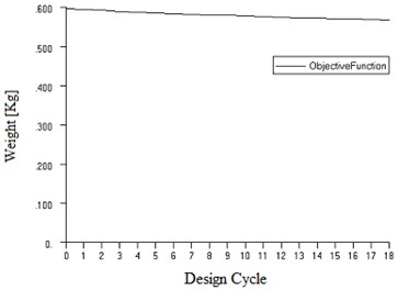
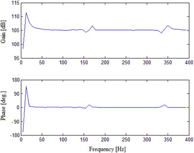
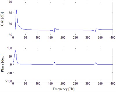
Fig. 12FRF numerical results of the unloaded shaker with optimized support spring plate
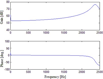
a) In useable frequency range
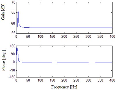
b) In low frequency area
To test the new support spring plate, FR analysis was carried out on the optimized E-shaker’s moving system. The analysis still employed the modal frequency response analytic method. Axial force changing with frequency within 0 Hz-2500 Hz was exerted on the armature. Fig. 12 is the FRF of the unloaded shaker with optimized support spring plate.
As shown in Fig. 12, the FR curve displays desirable frequency and phase characteristics. The first order elastic natural frequency of the moving system reaches 4.97 Hz. Meanwhile there exist no undesirable humps within the low frequency area. So the optimized support spring plate not only expands the shaker’s useable low frequency range, but also effectively eliminates the humps in FR in low frequency area.
Table 4Initial value and optimal solution of design variables
Design variable | Initial value | Optimal solution |
3 mm | 1.9861 mm | |
3 mm | 1.9861 mm | |
3 mm | 1.9861 mm | |
0.5 mm | 0.2073 mm | |
0° | 0.069° | |
45° | 7.114° | |
90° | 14.50° |
5. Conclusions
1. With the combination of EMA and FEA, this study has verified that the humps appearing in the FR of conventional E shaker within its low frequency area are caused by the elastic resonance of support spring plates. It also proves the FEM of the shaker’s moving system is reliable to reflect the dynamic characteristics of the shaker and can be used for further optimum dynamic design.
2. As an effort to improve the low frequency performance of the E shaker, this study proposes a new support spring plate of laminated composite structure with viscoelastic damping material. The research findings indicate after optimization, the new spring plate can effectively suppress the humps of the FR in low frequency area and lower the minimum value of the shaker’s useable frequency range.
References
-
Lang G. F. Electrodynamic shaker fundamentals. Sound and Vibration, Vol. 31, Issue 4, 1997, p. 14-23.
-
Zhao C. S. A Research on Electrodynamic Shaker. Nanjing University of Aeronautics and Astronautics, 1990, (in Chinese).
-
Zhao C. S., Bao M. The research and the engineering application of electrodynamic vibrators. Journal of Nanjing University of Aeronautics and Astronautics, Vol. 25, Issue 5, 1993, p. 638-645, (in Chinese).
-
Bi S. H., Ren J., Wang W., Zong G. H. Elimination of transducer mass loading effects in shaker modal testing. Mechanical Systems and Signal Processing, Vol. 38, Issue 2, 2013, p. 265-275.
-
Koo J. H., Shukla A., Ahmadian M. Dynamic performance analysis of nonlinear tuned vibration absorbers. Communications in Nonlinear Science and Numerical Simulation, Vol. 13, Issue 9, 2008, p. 1929-1937.
-
Zhang W. H., Qiang J. Application of air spring on shale shakers. China Petroleum Machinery, Vol. 23, Issue 12, 1995, p. 39-42, (in Chinese).
-
Khalilian A., Chen P., Chancellor W. J. Analysis and testing of a spring-loaded tree shaker. Transactions of the American Society of Agricultural Engineers, Vol. 22, Issue 4, 1979, p. 756-760.
-
Lee G. M., Ju Y. H., Park M. S. Development of a low frequency shaker using MR dampers. Journal of Precision Engineering and Manufacturing, Vol. 14, Issue 9, 2013, p. 1647-1650.
-
Lang G. F. Understanding the physics of electrodynamic shaker performance. Sound and Vibration, Vol. 35, Issue 10, 2001, p. 24-33.
-
William T. T., Marie D. D. Theory of Vibration and Applications. Tsinghua University Press, 2005.
-
Zhao C. S. Research on high energy shaker and its applications in engineering. Measurement and Control Technology, Vol. 15, Issue 3, 1996, p. 8-11, (in Chinese).
-
Wang K., Zhang F., Chen G. P., Zhang A. P. Response mapping technique of structural dynamics based on finite element model. Journal of Vibration and Shock, Vol. 29, Issue 11, 2010, p. 35-37, (in Chinese).
-
Li H., Yang B. K., Yan G. R. Hu J. W. Vibration control simulation of an electrodynamic shaker based on an electromagnetic finite element model. International Journal of Applied Electromagnetics and Mechanics, Vol. 39, Issues 1-4, 2012, p. 769-777.
-
Zhang S. Vibration Test and Analysis Technology. Tsinghua University Press, Beijing, 1992, (in Chinese).
-
Guo H., Zhou X. W., Zhang H. Stress field analysis and structure design of composite material plate spring. Acta Materiae Compositae Sinica, Vol. 13, Issue 4, 1996, p. 64-69, (in Chinese).
-
Nakagaki M., Matsumoto R., Nakamichi Y. Equivalent material modeling for composite of damaged inclusions with spring layer. 11th International Conference on Fracture 2005, ICF11, Vol. 2, 2005, p. 1198-1203.
-
Jones R. M. Mechanics of Composite Materials. Second Edition, CRC Press, 1998.
-
Liu. Y., Shimoda M. Parameter-free optimum design method of stiffeners on thin-walled structures. Structural and Multidisciplinary Optimization, 2013, p. 1-9.
-
Baldomir A., Hernandez S., Diaz J., Fontan A. Sensitivity analysis of optimum solutions by updating active constraints: application in aircraft structural design. Structural and Multidisciplinary Optimization, Vol. 44, Issue 6, 2011, p. 797-814.
-
Ma J., Gao W., Wriggers P., Chen J., Sahraee S. Structural dynamic optimal design based on dynamic reliability. Engineering Structures, Vol. 33, Issue 2, 2011, p. 468-476.
-
Lakshmi K., Mohan R., Rama A. Optimal design of laminate composite isogrid with dynamically reconfigurable quantum PSO. Structural and Multidisciplinary Optimization, Vol. 48, Issue 5, 2013, p. 1001-1021.
-
Perdahcioglu D. A., Geijselaers H. J. M., Ellenbroek M. H. M., De Boer A. Dynamic substructuring and reanalysis methods in a surrogate-based design optimization environment. Structural and Multidisciplinary Optimization, Vol. 45, Issue 1, 2012, p. 129-138.
About this article
This paper is supported by Six Talent Summit Foundation of Jiangsu Province, China (No. ZBZZ-038).
