Abstract
The complex impulse environment of artillery firing process brings very tough impulse resistance requirement for the artillery carrier equipment. The results of the vibration test of an electrical control box with a certain rubber shock absorber show that good shock absorb effect has not been received. Based on carefully theoretical analysis and simulation, it can be sure that the rigid collision when shock absorber reaches its limit is the reason. From the point of view of the theory and simulation of the experimental results, the analysis of the experiment results is given, which can provide the necessary theoretical basis of how to choose the appropriate shock absorber.
1. Introduction
The artillery firing process combines the high temperature, high speed, high pressure and complex strong impact, which are the main characters that make the artillery to be different from other mechanical systems. The problems that the artillery carrier equipment may have to face during the firing process are: when the connector with no additional tightening measures fall from the slot, it may cause other components’ damage; it will brings the resonance when the natural frequency and excitation frequency is the same [1]; mechanical deformation of the structure of the device and brittle fracture; screw connection loosen or even fall off and hit other parts. Therefore, it is very important to eliminate the vibration of the artillery carrier equipment.
Besides eliminating vibration, vibration absorption, damping, dynamic design, the most widely used measurement is vibration isolation technology [2]. With the excellent characters of noise reduction performance and low cost, the rubber shock absorber are widely used in various mechanic structure. The rubber shock absorber’s properties are mainly reflected by the response of mechanic structure under dynamic loads. The loads of artillery firing is highly transient, and non-cyclical, therefore the response under the transient complex dynamic loads of the artillery firing is very important [3-6].
2. Experiment of rubber shock absorber
The object of this experiment, electrical control box, can directly influent the working situation of the artillery as one of the artillery carrier equipment [7]. Because it can suffer massive instantaneous shock impact loads when the artillery is firing, some reasonable shock absorptions are very necessary to ensure that the electrical control box can work safely.
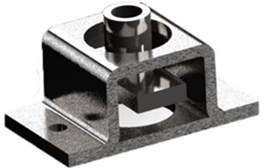
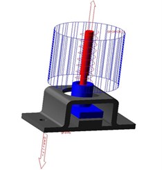
A certain rubber shock absorber was chosen for this experiment and the object is illustrated as Fig. 1. This shock absorber was combined of three parts: mounting base, rubber filler, mounting bracket. The mounting base and mounting bracket were made of cast iron. The inner situation is illustrated as Fig. 2. The mounting base and mounting bracket didn’t have directly rigid contact and there were some rubber materials which have certain rigidity and damping filling between them [8-9].
According to the mechanic handbook, the rigidity of this kind of rubber shock absorber is 500 N/mm, damping ratio is 0.1 and maximum static deformation is 1 mm. Considering the size and structure of the equipment, 4 rubber shock absorbers were used in this experiment and they were placed in the four bottom corners of the electrical control box. What’s more, 8 M6 threaded fasteners were used to fix all the system.
Fig. 1Rubber shock absorber
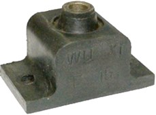
Fig. 2Inner situation of absorber
The accelerator sensors were stuck on the electrical control box by the adhesives, approaching the 4 corners which have the maximum rigid parameter. The comparison experiments were conducted by the variables-control method. The independent reproducible of the experiments were secured by the control of system input. Physical comparison signals were the vibration signals before and after of shock damping. The acceleration acquisition system was consisted by Deve 1201 data acquisition system (Fig. 3).
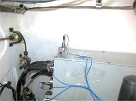
The field experiment system is illustrated as Fig. 4.
Fig. 3Deve 1201 data acquisition system
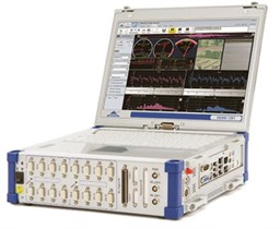
Fig. 4Field experiment system
The obtained accelerating signals needed to be transformed and its principle was “irregular pulse acceleration signal equivalent half-sine waveform, and then follow with the development of tolerance half-sine waveform evaluation”.
Now transformed an accelerating signal detected in an impulse experiment. We used Fast Fourier Transform and chose a good cutoff frequency to filter of acceleration. The data images before and after the waveform filtering are shown as Figs. 5-6.
Fig. 5Data image before waveform filtering
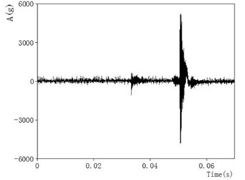
Fig. 6Data image after waveform filtering
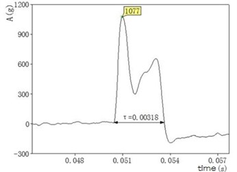
Semi-sinusoidal equivalent processing was standard half-sine whose impulse amplitude was and pulse duration was . After the integration process, we obtained its velocity:
With the above filtering and half-sine equivalent treatment, we preceded four groups of experimental data. The results are shown in Table 1.
Table 1Four groups of experimental data
Test number | Before the shock | After the shock | ||
Acceleration peak (g) | Pules width (ms) | Acceleration peak (g) | Pules width (ms) | |
1 | 4 | 10 | 51 | 3.5 |
2 | 12 | 3 | 25 | 20 |
3 | 8 | 4.5 | 60 | 2.5 |
4 | 10 | 3.5 | 71 | 2.5 |
3. Analysis of vibration system
Based on the experimental phenomena of shock reduce system’s impact peak acceleration increasing, this section explains it based on the system dynamic and collision. First of all, because the rubber shock absorber’s mass was much smaller than the electrical control box, the shock absorber model could be simplified as the combination of a spring unit with 2000 N/mm and damping unit with 0.8 N⋅s/mm. Furthermore, the whole system could be simplified as a single degree of freedom damped mass-spring system after introduced the electrical control box, which had a certain mass. According to the theory of mechanical vibrations, after the semi-sinusoidal equivalent excitation on the rubber shock absorber mounting bracket, the mass unit response of single degree of freedom damped mass-spring system was:
where was the mass of electrical control box, was the damp of rubber shock absorber, was the natural frequency of the single degree of freedom mass-spring system, and were the initial displacement and initial velocity of the vibration system:
was the response of the single degree of freedom damped mass-spring system based on the initial conditions.
was the response of the single degree of freedom damped mass-spring system based on the Equivalent incentives.
The initial state of the experimental system under gravity was static equilibrium and therefore the response caused by the initial conditions is zero. The response of the mass of single degree of freedom damped quality spring system can be simplified as:
Based on previous vibration theory, we used the MATLAB to calculate the system response by using the convolution and differential operation. The results showed that peak acceleration was less than the maximum acceleration which was not installed shock absorber. Single degree of freedom damped mass-spring system did not appear to increase the acceleration phenomenon. Therefore the damped spring-mass system may reach the elastic limit of the spring and in a non-compressed state which caused the instantaneous collision. It would lead to a sharp increase in instantaneous acceleration and affect the safe operation of the electrical control box and life.
In multi-body dynamics software Adams, the system dynamics model was built up as show in Fig. 7.
Fig. 7System dynamics model
The kinetic model was composed of four parts, including the damper base, shock absorber bracket, electrical control box and a spring damper unit. First, set the direction of gravity and the gravity value of the whole system. Then set the constraint relationship of each part, damper base fixed on the ground, electrical control box fixed on the shock absorber bracket, spring shock absorber damping element acting between the bracket and the damper base and set between the two sliding pair member, which limiting the direction of movement. Finally, semi-sinusoidal excitation was applied on the shock absorber bracket equivalent. Defined the contact parameters damper between the base and the shock absorber bracket based on the collision function contact algorithm:
Semi-sinusoidal equivalent excitation was set as IF (-0.001:4000(∙/0.001), 0, 0), which means it was the 4000 N peak value half-sine during the 0 and 0.001 s and none incentives after 0.001 s. Spring damper unit parameter was set to the stiffness 2000 N/mm, damp 0.8 N⋅s/mm. Damper base contact between stiffness and shock absorber bracket was . Instantaneous normal force in the material stiffness contribution index was 2.2, damp 10 N⋅s/mm. Full damping penetration depth was 0.1 mm.
Before dynamics simulation, the static equilibrium system was reached to restore the true initial state, which let the springs in pre-compressed state under the control of electrical control box. Set simulation time 0.02 s, computed nodes 2000 and finally run the simulation calculation:
Simulation speed and acceleration of electrical control box were shown as Figs. 8, 9:
The conclusion can be reached according to the pictures:
From 0 to 0.001 s, the electrical control box’s velocity increased to 125 mm/s and produced acceleration whose peak was about 20 g.
After 0.001 s, the outer stimulation disappeared and the electrical control box moved under the spring damping unit with a certain amount of compression. The vibration of the entire system could be described as the free oscillation damping with the initial state.
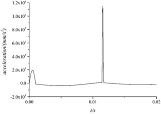
About 0.0115 s, the velocity of the electrical control box changed rapidly. From the view of model, it could be described as follow. After lost the outer stimulation , the electrical control box moved under the effect of spring damper unit. When it came to the reverse maximum speed, the spring means reaches its maximum compression 0.1 mm, which caused the fierce collision and caused measured acceleration surge.
Fig. 8Speed of electrical control box
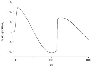
Fig. 9Acceleration of electrical control box
4. Conclusions
In the rubber shock absorber damping experiments, the using of rubber shock absorber didn’t reduce the shock effect and made the peak acceleration doubled in the contrast. By the dynamics and collision theory and simulation analysis of the experiments, the causes were located. The shock absorber reached its elastic limit and caused the rigid collision. Therefore, it is very important to choose the match shock absorber in the practice. If some wrong shock absorbers are chose, just as the experiments, it will cause the collision and impact rather than absorbing shock.
This article analyses the experiments from the view point of experiment and simulation and provides important theoretical basis for the choosing of good shock absorbers. Further works will focus on the systematical theory analysis of damped mass-spring system and provide the general rules of dampers choosing.
References
-
Yu H. J., Fang K. Comparison of shock absorption and buffering property of main shock absorbers in some radar. Journal of Modern Rader, Vol. 32, 2010, p. 99-102.
-
Zeng C., Hua H. X. Study on shock response characteristics of nonlinear rubber isolator. Journal of Noise and Vibration Control, Vol. 4, 2012, p. 20-24.
-
Singh O. P, Sreenivasulu T., Kannan M. The effect of rubber dampers on engine’s NVH and thermal performance. Journal of Applied Acoustics, Vol. 75, 2014, p. 17-26.
-
Ren C., Pan H. X. Study of shock response spectrum based on shocking signal. Journal of Gun Launch and Control, Vol. 3, 2010, p. 21-24.
-
Ma F. X., Wang Z. H., Wang H. L. Development of aviation metal rubber damper Journal of Noise and Vibration Control, Vol. S2, 2009, p. 322-325.
-
Wang G. Y. The design principle and performance test of rubber damper. Journal of Special Purpose Rubber Products, Vol. 19, 1998, p. 42-47.
-
Jiang Q. B., Jia D. M. Application of rubber material in the shock absorber. Journal of China Rubber Industry, Vol. 51, 2004, p. 114-119.
-
Meimand V. Z., Schafer B. W. Impact of load combinations on structural reliability determined from testing cold-formed steel components. Journal Structural Safety, Vol. 48, 2014, p. 25-32.
-
Igor G., Mihail G. A polynomial analytical model of rubber bearings based on series of tests. Journal Engineering Structures, Vol. 56, 2013, p. 600-609.
About this article
