Abstract
An approach to synthetically evaluate structure-borne noise and shock resistance of gear system is proposed. Firstly, dynamic finite element mesh model of gear system which includes shafts, bearings, gears and housing is established by using spring element, tetrahedral element and hexahedral element. Then dynamic finite element analysis model of gear system is gotten by loading the dynamic excitation force which can be calculated via the computation program of gear pair stiffness excitation, error excitation and impact excitation onto the tooth meshing line as boundary conditions. And the dynamic response of gear system is analyzed by using modal superposition method, and the vibration response experimental study of gear system is performed on the gearbox test-bed. The comparative analysis shows that computational results of the vibration response are in good agreement with the data of experiment tests and it could verify the rationality of dynamic finite element mesh model of gear system. Finally, taking acceleration shock excitation load into account on the basis of the dynamic finite element mesh model, the impact response of gear system is solved, and the shock resistance is analyzed based on the strength decision criterion.
1. Introduction
As the gear drive has characteristics such as great load capacity, long lifespan, high reliability and smooth operation, it is widely used in marine vessels, traffic transportation, metallurgic buildings and engineering machinery, etc. Along with the development of science and technology, the gear drive is now growing to transmit higher power, higher speed, and lower noise. Because of the diverse of excitation sources, the high excitation frequency and the great meshing impact, the research of vibration noise is becoming more and more important, especially for marine gear devices. They undergo not only the dynamic excitation caused by tooth stiffness excitation, error excitation and meshing impact excitation, but perhaps also the unpredictable external acceleration shock. The violent vibration noise caused as above will affect the stealth performance of the driving system, as well as the reliability and vitality of the marine vessels.
Many scholars have done a number of theoretical studies on the vibration noise of gear system. Considering the nonlinear factors, such as time varying meshing stiffness [1, 2], meshing impact [3, 4], backlash [5, 6] and tooth shape deviations [7], the dynamic lumped parameter model of the gear system was built and the influence of different factors on the vibration response of the driving system was also studied. The author also used the finite element method to develop the vibration response analytical model of gear system and calculate the vibration velocity and vibration acceleration of the gear system, and did experiment to test the structure-borne noise [8]. As for the research of shock resistance, Sekua presented a methodology which is able to perform real-time impact load identification [9]; Jin proposed an analytical method based on the wave theory to calculate the pressure at the interfaces of coated plate subjected to underwater weak shock wave [10]; Luo used the finite element method to analysis the shock response of the ST drive from Seagate [11]; Younis presented modeling, simulation, and characterization for the dynamic response of clamped-clamped microbeams under mechanical shock [12].
In spite of the above-mentioned studies focusing on the modeling and simulation of dynamic response, there are very quite few studies about the prediction of structure-borne noise and the shock resistance of gear system. Although the author did partial research work about them, there are still some problems as follows:
The study object of the vibration response often restricted to the gear driving system, but not the coupled system combining the gear driving system with the structure system, which would influence the accuracy of the dynamic analytic result; the study object of shock resistance was rarely related to complex gear systems; and they are not commonly used models to asses the structure-borne noise and shock resistance of gear system. These gaps will be the emphases of this current paper.
2. Analysis of dynamic excitation load of the gear system
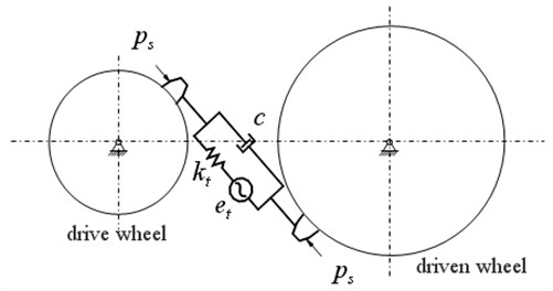
According to vibration theory, the gear transmission is simplified as a vibration system with concentrated parameters, shown in Fig. 1, so the nonlinear dynamic equation of gear pair can be expressed as:
where is the equivalent mass of the gear pair on contacting line; is the dynamic relative displacement; is the damping coefficient; is the time varying meshing stiffness; is the static relative displacement; is the gear synthetic error which is a function of time; and is the static load.
Fig. 1Gear vibration system model
Equation (1) can be rewritten as:
Namely:
where is the average stiffness of the gear tooth; is the varied part of the meshing stiffness; is the shock excitation force which is related to the gear error and the time varying stiffness.
After approximate alternative, the nonlinear vibration equation of gear pair can be expressed as linear vibration equation:
The left item of the equation is the vibration excitation force , it comprises two parts: for stiffness excitation and error excitation; for meshing impact excitation.
Stiffness excitation of the gear pair is a kind of parametric excitation, which synthesizes the dynamic excitation caused by time varying characteristics of meshing stiffness during the gear meshing process; error excitation is a kind of displacement excitation, which is caused by collision and impact between gear teeth, where the collision and shock are bringing about by change of instantaneous transmission rate as a result of manufacturing error and installment error; and tooth impact excitation is a kind of meshing dynamic excitation caused by gear errors and loading deformation.
Error excitation can be computed according to gear deviation provided by accuracy class. In this paper, the profile error and basic pitch error of the gear tooth expressed by a sine function are as follows:
where describes the profile error and basic pitch error; and are respectively the mean and the dynamic values of transmission error, ; is time; is meshing period of a single tooth, ; is gear contact ratio; is phase angle, .
Meshing impact excitation of gear tooth is a kind of load excitation, and it is hard to define by conventional method. This paper presents three dimensional impact dynamic contact finite element mixing method to deal with the dynamic numeric simulation [14].
The interior dynamic excitation load of gear pair can be acquired by synthesizing stiffness curve, error curve and meshing impact excitation curve. The procedure is as follows:
- First, the single tooth mesh stiffness is multiplied with the error excitation at the corresponding contact points.
- Second, impact excitation is added to the multiplication results.
- Third, the mean value is subtracted from results obtained in second step to obtain the dynamic component.
- Finally, the combined effect of all tooth pairs in contact can be derived by combining the individual single tooth mesh stiffness excitation, transmission error excitation, and the dynamic mesh forces of those loaded tooth pairs at each meshing position.
According to the dynamic excitation mechanism and method above-mentioned, the dynamic excitation automatic analysis software Gbvna is developed via Visual Basic language. This software could build tooth contact finite element model about stiffness excitation of gear pairs, and analyze the time varying stiffness of gear pairs. It could obtain shock dynamic contact finite element model about backlash nonlinear problems of gear pairs, and numerically simulate the impact excitation of meshing impact process. It could also determine gear error according to gear accuracy class, and form gear error excitation curve, and analyze gear interior excitation by combining stiffness excitation and impact excitation. Fig. 2 shows the structure diagram of a marine vessel gearbox which uses four-stage helical gear pair transmission. Combined with the gear parameters of the marine vessel gearbox, the dynamic excitation curve of each stage of gear system can be calculated by using the self-developed software Gbvna. Fig. 3 shows the dynamic excitation force of the second-stage gear pair of the gearbox.
3. Finite element model of gear system
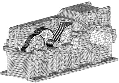
According to the design drawing of the reducer, the solid model of the gear system is built, which includes four-stage involute helical gear pairs, transmission shafts, bearings and housings, as shown in Fig. 4(a). And the dynamic finite element mesh model of the whole gear system would be obtained by using the tetrahedral element and hexahedral element to automatically mesh all components and parts of the gearbox after importing the solid model into ANSYS software. Establish spring element COMBIN14 both between shaft and housing and between gear pairs according to bearing and meshing stiffness so as to simulate the bearing support and the meshing relationship of gear pairs. The finite element analysis mesh model with a total of 246849 elements and 84512 nodes is shown in Fig. 4(b).
Fig. 2Structure diagram of a marine vessel gearbox
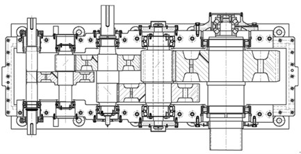
Fig. 3The dynamic excitation force of the second-stage gear pair
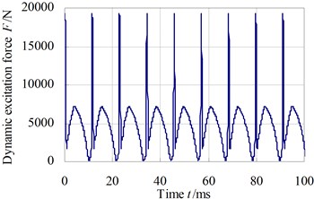
Fig. 4The finite element model of gear system
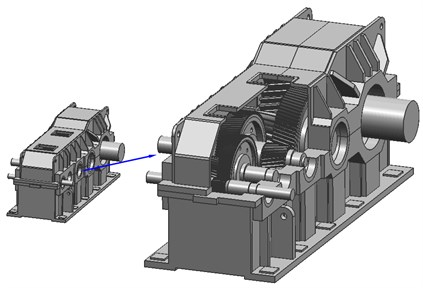
a) Solid model
b) Finite element mesh model
4. Vibration response analysis of the gear system
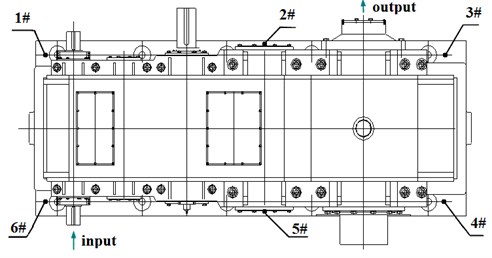
Fig. 5 shows the distribute diagram of vibration response computing nodes (these locations are also used for experimental test) of the gear system. Nodes 1#~6# are respectively located on the six foundation bolt of the gearbox, and we mainly calculate vibration acceleration of vertical direction ( direction).
Fig. 5The distribute diagram of vibration response computing nodes
The dynamic excitation force and boundary restrains of the gear system are applied onto each loading node on the engagement line of relative gears along the normal vector direction of the tooth surface, and the boundary restrain are applied onto positions of the gearbox. Because there are so many load-steps and loading nodes, we adopt the ANSYS Parametric Design Language (APDL) to automatically load the dynamic excitation force onto nodes on contacting lines of gear pair according to the time step, and the zero displacement restrain is also loaded on each bottom node of box foundation. Then the vibration response of the gear system can be analyzed by using the modal superposition method. The input shaft rotates anticlockwise. The computing time step of dynamic response is 0.0577 ms, the total time is 1000 ms, and the damping ratio is 0.04.
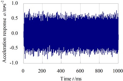
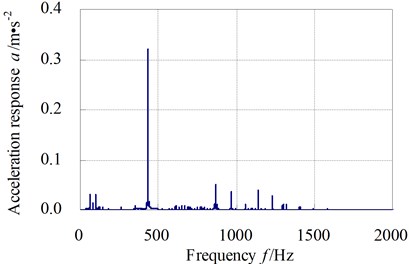
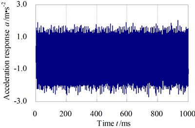
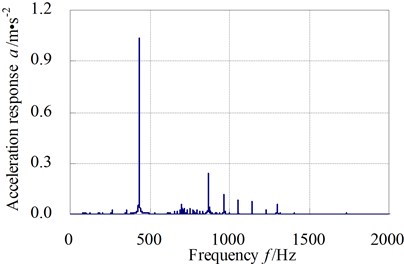
Table 1 shows the root-mean-square (RMS) values of direction vibration acceleration of computational nodes on the six foundation bolts. Fig. 6 and Fig. 7 respectively show the time domain and frequency domain curves of direction vibration acceleration of computational node 3# and 6#.
The results show that the vibration acceleration response of computing node 6# is larger, mainly because the position of the computational node is situated near the input shaft; and the peak of vibration acceleration response curves in frequency domain appear near the meshing frequency of gear system.
Table 1The RMS values of vibration acceleration of six computational nodes (unit: m·s-2)
Node no. | 1# | 2# | 3# |
-direction | 0.78 | 0.38 | 0.36 |
Node no. | 4# | 5# | 6# |
-direction | 0.22 | 0.42 | 1.15 |
Fig. 6The Y-direction vibration acceleration response of computational node 3#
a) Time domain
b) Frequency domain
Fig. 7The Y-direction vibration acceleration response of computational node 6#
a) Time domain
b) Frequency domain
Structure-borne noise of gear system is another expressing way of vibration response of the gearbox, and the surface vibration of gearbox can be expressed by acceleration or acceleration level. Acceleration level of structure-borne noise can be defined as:
where: – the acceleration level of structure-borne noise, (unit: dB); – the acceleration effective value of frequency range with a frequency as the center frequency, (unit: m/s2); – the reference acceleration, 1×10⁻⁶ m/s2.
Fig. 8 respectively show the structure-borne noise levels of direction real life vibrationacceleration of computational nodes 3# and 6# from 16 Hz to 8000 Hz while the input shaft is rotating anticlockwise. The plots show that the maximum of structure-borne noise of acceleration level of computing nodes 3# and 6# in the frequency range are respectively 110.6 dB and 120.7 dB; the maximum of 1/3 octave structure-borne noise of direction vibration acceleration of computational nodes 3# and 6# arises at nearby 400 Hz, this frequency range mainly reflect meshing frequency of gear pair, from which we could see structure-borne noise of gearbox is mainly caused by tooth meshing vibration.
Fig. 8Y-direction vibration acceleration structure-borne noise level of computational node
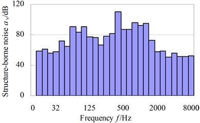
a) 3#
b) 6#
The experiment of this paper is carried out on the over-all characteristic test-bed shown in Fig. 9. It should note that we just measure the real life acceleration time signals on a test gearbox (not a real main reducer used in ship lift drive system). The test-bed consists of speed-up gearbox, experimental gearbox, hydraulic dynamometer, universal coupling, DC machine and hydraulic system platform, etc. DC machine applies load through machine controller; experimental load is loaded by hydraulic dynamometer, which can be controlled by gearbox observing and controlling system. Test instrument includes B&K4382 acceleration sensor, B&K2635 charge amplifier, INV306U-5260 intelligent signal collecting analyzer and sound level meter, etc. While vibration characteristic testing, the vibration signal (acceleration vibration signal) measured by BK4384 piezoelectric accelerometer is amplified and integrated to velocity vibration signal by DLF-8 charge voltage filtering integral amplifier. Then, the velocity signal is delivered to INV306U-5260 intelligent signal collecting analyzer to be collected. And lastly, the signal could be recorded and analyzed in the DASPV10 signal analysis system, and the 1/3 octave structure-borne noise of acceleration level will be obtained.
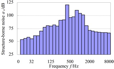
Fig. 10 respectively show the comparative curve of test values with the calculating values of 1/3 octave structure-borne noise of acceleration level of test point 3# and 6#. The results show that the simulation values of structure-borne noise of gearbox essentially agree with the test values in various frequency bands 16 Hz~8000 Hz, and the mean of errors between simulation value and test value are respectively 11.1 % (test point 3#) and 9.0 % (test point 6#); and the frequency of structural noise peak occurs at the gear mesh frequency. All of these would verify the rationality of finite element mesh model of the gear system, and that the computational model does represent the real structure in some ways.
Fig. 9Overview of the gearbox vibration characteristic test-bed
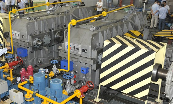
Fig. 10The comparative curves of simulation structure-borne noise with test values of test point
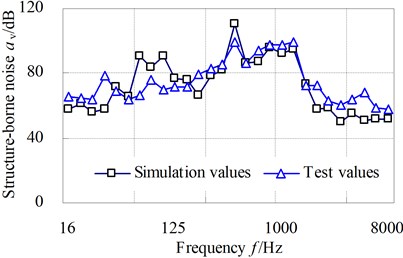
a) 3#
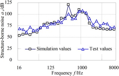
b) 6#
5. Shock resistance analysis of gear system
The acceleration shock excitation of the gear system can be simulated as shock pulse or shock response spectrum and be used to simulate the actual shock loads, where the shock pulse usually adopts half-sine pulse and triangular (saw-tooth) pulse. This paper uses time domain curve of half-sine acceleration pulse to simulate shock acceleration excitation, and the duration of shock pulse waveform is 11 ms. The mathematical expression is:
where is the amplitude of shock pulse waveform; .
Fig. 11 shows the shock excitation load when shock acceleration is 15 g (i.e. 150 m/s2).
Because the dynamic stresses caused by interior dynamic excitation are too small compared to the corresponding values under acceleration shock excitation of the gear system, there is no need to take the influence of interior dynamic excitation into consideration when calculating the shock resistance of gear system on condition that revolving speed is not high, machine accuracy is high and the interior dynamic excitation is small. On the basis of finite element mesh model of the gear system in section three, the acceleration shock excitation loads of the gear system are respectively applied to all nodes on the gearbox foundation in the , , direction, and the foundation of the finite element computational model of gear system accordingly exists motion freedom in , , direction.
The dynamic response characteristics of gearbox under acceleration shock excitation 10 g, 15 g and 20 g respectively are solved by employing Full method in ANSYS software during a transient dynamic analysis, and the shock vibration acceleration and dynamic stresses of the gear system would be obtained.
Fig. 11The shock excitation curve when the shock acceleration is 15 g
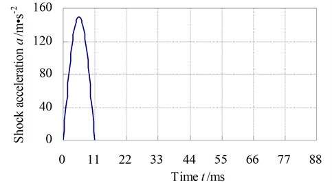
Table 2 shows the maximum values of dynamic stress of gearbox under acceleration shock excitation 10 g, 15 g and 20 g. The results show that the maximum value of dynamic stress of the gearbox appears at the bearing seat rib plate zone of the box output end.
Fig. 12 shows shock vibration acceleration response of the node on bearing seat rib plate zone of the box output end when the gearbox is applied to acceleration shock excitation 15 g in direction .
Fig. 13 shows the dynamic stress curve of node on bearing seat rib plate zone of the box output end when the gearbox is applied to acceleration shock excitation 15 g in direction .
Fig. 14 shows the dynamic stress cloud map when the gearbox is applied to acceleration shock excitation 15 g in direction , and the unit in this figure is Pa.
The shock resistance of the gear system can be mainly evaluated from these aspects as follows: the peak value of vibration velocity or vibration acceleration, the stiffness criterion and the strength criterion. In this paper we use the strength criterion to determine the shock resistance ability of the gear system.
Table 2The maximum values of equivalent stress of gearbox under shock acceleration excitation (unit: MPa)
Shock excitation | 10 g | 15 g | 20 g |
-direction | 41.3 | 53.2 | 78.5 |
-direction | 20.8 | 27.6 | 57.8 |
-direction | 124.7 | 137.0 | 208.2 |
Fig. 12The shock vibration acceleration response of the node when the shock acceleration is 15 g
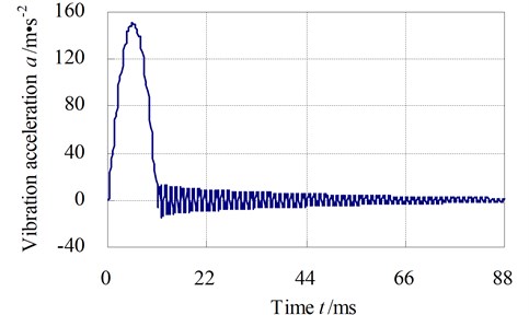
Fig. 13The dynamic stress curve of node when the acceleration shock excitation is 15 g
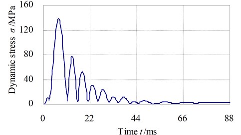
Fig. 14The dynamic stresses of gearbox when the shock acceleration is 15 g
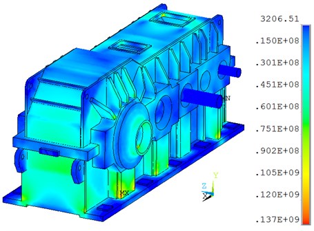
From Table 2, we can see that the dynamic stresses under acceleration shock excitation 10 g, 15 g, 20 g in and direction are small, so the shock resistances in and direction are strong; the dynamic stress under the acceleration shock excitation 20 g in direction is 208 MPa, it is a little smaller than the yield strength 235 MPa of box material. But when taking safety factor of gearbox into account, the shock resistant capacity of the gearbox is about 15 g and the gearbox under shock pulse will not engender plastic deformation, flaws or other mechanical damages.
In conclusion, the bearing seat rib plate zone of the gearbox output end is sensitive to shock wave, so this factor will be an important consideration in shock-resistant design. And the shock isolation design must mainly focus on the high frequency oscillator about 5 ms-40 ms after shock.
6. Conclusions
(1) An approach to synthetically evaluate structure-borne noise and shock resistance of gear system is proposed; and the dynamic excitation automatic analysis software is developed via Visual Basic language.
(2) The dynamic response of gear system is analyzed by using modal superposition method, and the vibration response experimental study of gear system is performed on the gearbox test-bed; the computational results of the vibration response are in good agreement with the data of experiment tests and it could verify the rationality of dynamic finite element mesh model of gear system.
(3) Taking acceleration shock excitation load into account on the basis of the dynamic finite element mesh model, the impact response of gear system is solved, and the shock resistance is analyzed based on the strength decision criterion.
References
-
Fernández A., Iglesias M., De-Juan A., et al. Gear transmission dynamic effects of tooth profile deviations and support flexibility. Applied Acoustics, Vol. 77, 2014, p. 138-149.
-
Wang J., Lim T. C., Li M. Dynamics of a hypoid gear pair considering the effects of time-varying mesh parameters and backlash nonlinearity. Journal of Sound and Vibration, Vol. 308, Issue 1-2, 2007, p. 302-329.
-
Byrtus M., Zeman V. On modeling and vibration of gear drives influenced by nonlinear couplings. Mechanism and Machine Theory, Vol. 46, Issue 3, 2011, p. 375-397.
-
Chen S., Tang J., Wu L. Dynamics analysis of a crowned gear transmission system with impact damping Based on experimental transmission error. Mechanism and Machine Theory, Vol. 74, 2014, p. 354-369.
-
Moradi H., Salarieh H. Analysis of nonlinear oscillations in spur gear pairs with approximated modelling of backlash nonlinearity. Mechanism and Machine Theory, Vol. 51, 2012, p. 14-31.
-
Lin T. J., Wang D. H., Ran X. T. Coupled nonlinear vibration analysis of a multi-stage gear transmission system. Journal of Vibration and Shock, Vol. 32, Issue 17, 2013, p. 1-7,23.
-
Baguet S., Jacquenot G. Nonlinear couplings in a gear-shaft-bearing system. Mechanism and Machine Theory, Vol. 45, Issue 12, 2010, p. 1777-1796.
-
Lin T. J., He Z. Y., Geng Y. Y. Prediction and experimental study on structure and radiation noise of subway gearbox. Journal of Vibroengineering, Vol. 15, Issue 4, 2013, p. 1838-1846.
-
Sekua K., Graczykowski C., Holnicki-Szulc J. On-line impact load identification. Shock and Vibration, Vol. 20, Issue 1, 2013, p. 123-141.
-
Jin Z., Yin C., Chen Y. An analytical method for the response of coated plates subjected to one-dimensional underwater weak shock wave. Shock and Vibration, Vol. 2014, 2014, p. 1-13.
-
Luo J., Shu D. W., Shi B. J. The pulse width effect on the shock response of the hard disk drive. International Journal of Impact Engineering, Vol. 34, Issue 8, 2007, p. 1342-1349.
-
Younis M. I., Alsaleem F., Jordy D. The response of clamped-clamped microbeams under mechanical shock. International Journal of Non-Linear Mechanics, Vol. 42, Issue 4, 2007, p. 643-657.
-
Liu W., Lin T. J., Li R. F. Dynamics performance analysis on gear system under shock spectrum. Journal of , Vol. 33, Issue 1, 2010, p. 7-11.
-
Lin T. J., Ou H., Li R. F. A finite element method for 3D static and dynamic contact impact analysis of gear drives. Computer Methods in Applied Mechanics and Engineering, Vol. 196, Issue 9-12, 2007, p. 1716-1728.
About this article
The research work was funded by the National Natural Science Foundation of China under Contract No. 51175524 and National Science and Technology Support Project under Contract No. 2013BAF01B04.
