Abstract
The paper demonstrates methods for testing and selecting composite ceramics-compounds by solving inverse problems of mechanics. A method for the identification of physical and mechanical characteristics of the compound is proposed. The idea of the method is that the studied material is connected with other materials, the characteristics of which are well known and differ from the characteristics of the material. Desired physical and mechanical properties should be considered unknown in the proposed calculation model. Values of the parameters can be measured accurately with experimental methods in the process of product operation. Characteristics of test materials and geometric dimensions of proposed structures are suggested. The solution of the problem of optimizing the tolerances of physical and mechanical characteristics of materials is proposed. In order to ensure the strength of the structure, the geometric dimensions of the composite construction ceramic resistor-compound are suggested.
1. Introduction
The sealing of electronic equipment elements is widely used to improve the reliability of their operation in terms of temperature, pressure, moisture, etc. [1, 2]. In particular, sealed composite flat micromodules (FMMs) are used in the control equipment of aircraft and rocket industries.
During the operation of FMMs, the structure “electronic element-compound” is subject to dangerous stresses. The stresses are caused by the difference of the coefficients of linear thermal expansion, Poisson’s ratio and elastic moduli of these materials. This leads to the destruction of FMMs and the consequent destruction of the expensive complex systems they belong to.
In order to eliminate such defects in the resistor-compound structure, it is necessary to provide the strength of the materials of the resistor and the sealant. In order to do this, the primary factors that influence the magnitude of the stresses in the materials of the resistor and the sealant have to be determined. The ranges of their values (tolerance) have to be found. These values ensure that the conditions of strength for each of the components of the mentioned structure are met:
The carried out analysis demonstrates that variations in physical and mechanical properties of compounds in the production of FMMs can reach 300 %. This depends on many factors, even such as the manufacturing location of compound components.
Existing methods for determining the physical and mechanical properties of materials have a number of drawbacks. These drawbacks significantly narrow the range of applications [3]. Speaking of static methods, since the studied materials are usually fragile, a couple of matters should be taken into consideration. Firstly, there are difficulties of complying with the alignment when attaching samples to testing machines. Secondly, the destruction of these samples occurs under low strain, which reduces the accuracy of measurement. Moreover, the results of this experiment are strongly dependent on the type of load, size of samples and their manufacture methods.
Dynamic methods can be applied only for materials with low absorption of oscillations. They depend on the temperature conditions under which the experiment is conducted. Moreover, in order to be effective, they require the information about the speed of propagation of elastic waves in the material.
In addition, both existing static and dynamic methods allow determining the physical and mechanical properties of generally homogeneous materials. In homogeneous materials, the value of these characteristics does not depend on the type of stress state of the material in a particular product. The considered compound exists as a sealant only in certain structures, such as FMM, and its physical and mechanical properties are different from the characteristics of the same compound in a different structure.
Thus, the problem of finding the methods for identification of physical and mechanical properties of compounds directly in real structures in the temperature range –60°C... –20°C is relevant.
2. Formulation and solution of the problem of identification
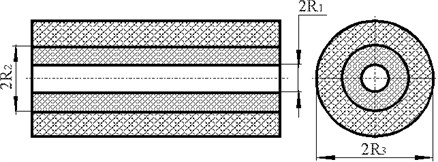
The study is focused on the causes of FMM destruction. It also provides a mathematical model of stress calculation in the “electronic element-compound” system [4], represented in Fig. 1 and Fig. 2. The formula for calculating the contact pressure in the materials of the resistor and the compound at a stable temperature yields Eq. (1):
where , is the coefficient of the linear thermal expansion in materials of the electronic component and the compound, respectively; , are elastic moduli; , is Poisson’s ratio.
Fig. 1Cross-section of an electronic element, compound on a base plate: 1 – base, 2 – isolated compound cylinder, 3 – electronic element
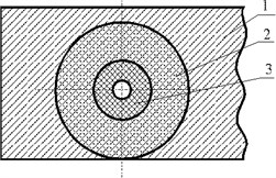
Fig. 2The electronic element surrounded by a layer of compound
An original method of calculations is developed. The calculations include parameters obtained by testing, which can simultaneously identify the coefficient of the linear thermal expansion, the elastic modulus and Poisson’s ratio of the compound.
The idea of the method is that the studied material is connected with other trial materials of known properties. These properties differ from the properties of the tested material. The connecting parts should have specific forms that make it possible to describe the stress-strain state of the samples in real structures with the same equations.
In order to determine physical and mechanical characteristics, the values of identified parameters should be considered to be unknown in the calculation model. It is suggested that parameter values of trial structures, which can be accurately measured by experimental means in the process of the product operation, should be inserted in the same model as input information. The same should be done with characteristics of trial materials and geometric dimensions. When producing a number of test samples with values of physical and mechanical properties (which are set so that the measured deformation values would be different), it is possible to write the number of linearly independent equations with identified parameters based on the computation model (which is required for their determination).
In order to identify the abovementioned physical and mechanical properties of the compound that seals and surrounds the resistor, double-layer cylindrical structures, “trial material – compound”, are made. The trial material with thoroughly investigated properties is chosen and differs from the properties of the compound. In these structures, contact pressure occurs at the interface of materials at temperature extremes. The parameters, which are included in the selected mathematical model and can be accurately measured by experimental methods, are strains emerging under contact pressure on the outer surface of the testing cylinder. Their values are connected by stress values of Hooke’s law. The ratio determined by Hooke’s law and the ratios specified by the authors of the developed model make it possible to find the value of the contact pressure for known radial sizes of structures (according to the experimentally determined values of strain).
According to the proposed model, the contact pressure can be considered as a structure parameter. It is determined experimentally and its value can be substituted in the calculation model as input information in the form of:
where is relative circumferential deformation of the contact surface.
The Eq. (1) for contact pressure is explored and turned into a form suitable for the determination of the identified parameters. The analysis of the right side of Eq. (1) demonstrates that its denominator is different from zero. The ratio is always preserved between the radial size of the studied structure and the value of Poisson's ratio for any material lies within .
The right-hand side of Eq. (1) is transformed into the following:
After introducing new variables expressed by parameters , , subject to identification, Eq. (3) is transformed. It is done in such a way that all the parameters that need definition should be located on the left side of the final equation. After performing the transformation and introducing additional notation, the following yields:
where The result is a linear equation with respect to unknown , , . For their determination, it is necessary to write a system of three linear algebraic equations. For this purpose, firstly, it is assumed that the sample is made of three different sets of values of the entire set of primary factors and the corresponding measured values of contact pressures. This adds the following system of equations:
where the indices of coefficients , , , and contact pressure correspond to the vector of parameters of the “” trial sample (1, 2,…, 3).
The solution of Eq. (5) can find the properties of the material being identified.
However, the method of test parameters doesn’t require setting various values of all parameters in order to achieve different values of contact pressures. It is enough to change one or more parameters in various combinations. Further, such options or their combinations are explored, which, firstly, are most easily changed, and secondly, which ensure the existence, uniqueness and stability of solutions of Eq. (5).
The condition [5, 6] for the existence and unity of solutions of the mentioned equations is that its determinant should not be zero, i.e.:
The analysis Eq. (6) shows that it cannot be met; for example, if the three studied samples have equal radii of ceramic resistors and outer radii of compound. This conclusion can exclude the consideration of some common cases; for example, the use of different trial materials in three samples with the preservation of the radial size of structures; or, changing contact pressure just by changing the internal diameter of the cylinder of the testing material. The further study of the system Eq. (5) shows that changing only the outer radius of the cylinder (made of the trial material with the preservation of the same values remaining coordinate vector of parameters in three samples) leads to the equations having trivial solutions.
To ensure the stability of the solution Eq. (5), and thus given accuracy, it is necessary to approximate angles [7-9] between straight lines, which are described by equations of the system Eq. (5). It is clear from the Eq. (5) that the most effective way is to change the geometric dimensions of devices included in the equation system.
Here are the most appropriate options for implementing the method of test parameters.
In the three studied samples, only the values of the contact surface radius are variable. improves the stability of the solution. In this case, in order to calculate the identifiable characteristics, it is necessary to put , 1, 2, 3 in Eq. (5). The condition should also be met.
In the three studied samples, simultaneous alteration occurs only if , , , , , 1, 2, 3 must be substituted into Eq. (5).
3. Experimental results
During the experiment, ceramic compounds are subjected to a thermo-shock in a range of temperatures between –20°C and –60°C. Due to the differences in physical and mechanical properties of materials, the contact pressure conditions the emergence of strains in materials.
The practical implementation of the method of test parameters in solving inverse problems for determining physical and mechanical properties of compounds requires, as mentioned earlier, the correct use of the design model of complex bilayer cylinders.
This implies meeting the following conditions: cylinders in the complex design should be thick. Double-layer composite cylinders must be long enough to prevent the influence of the edge effects at the point where the deformation occurs.
For the practical implementation of the method, a special device is developed and manufactured (Fig. 3). The main elements are a hollow cylinder (trial element), a hollow steel cylinder, a cylindrical bearing plate with two coaxial cylindrical grooves designed for fixation of tested compound and steel cylinders.
Three devices of this type are made with different diameters of elements (Table 1).
According to the measured values of strain, the amount of contact pressure is determined, using the Eq. (1). Then, the coefficient of the linear thermal expansion, the elastic modulus and Poisson’s ratio of the compound are calculated in different ranges of negative temperatures (Table 2).
The vector of nominal values of primary factors is defined as follows: .
Fig. 3Scheme of the device for determining physical and mechanical properties of the compound: 1 – hollow copper cylinder; 2 – hollow steel cylinder; 3 – tested compound; 4 – bearing plate
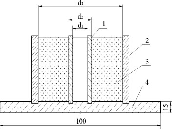
Table 1Cylinder diameters
Device # | Diameters, mm | ||
I | 10 | 10.4 | 40 |
II | 20 | 20.4 | 40 |
III | 30 | 30.4 | 60 |
Table 2Values of physical and mechanical properties of ceramic compounds
Temperature range | Young’s modulus , | Poisson’s ratio | Local thermodynamic equilibrium , |
–20…–30 | 13.794 | 0.294 | 7.0023 |
–30…–40 | 13.658 | 0.282 | 6.376 |
–50…–60 | 12.95 | 0.276 | 5.898 |
Next, it is necessary to determine regulated reasonable values of output characteristics of the model. A normalized histogram of loads that destroy ceramic resistors in tension is shown in Fig. 4. Loads of ceramic fractures of 50 resistors are measured in order to construct a normalized histogram, which is the empirical distribution density (DD) [10].
Since the empirical density of the destructive loads distribution value proved to be bimodal, a statistical analysis of test results is carried out. This is done by the method of processing data that are subject to the laws of the polymodal distribution (the splitting method mix) [11].
According to the proposed method, the two modal histogram is approximated by a linear combination of Gaussians with weights of the available:
where and is the expected value and standard deviation th sub-samples, each of which is influenced by its dominant parameters; is probability of falling into sub-samples; , , is a random variable and in this case coincides with the .
The use of the method splitting mixtures of probability distributions revealed that two modal combustible mixture distribution is described by Eq. (7) with parameters 0.66, 74, 6.6; 0.34, 114, 5.7 (Fig. 4).
For further processing, a subsample of resistors, in which destroying loads are subject to the law of normal distribution with parameters 74 N, 6.6 N, is studied, i.e. resistors with the least strength, while a possible error for the entire sample, goes to a margin of safety. Using the method of confidence intervals, it is found that with the probability of 0.995, the limit failure load can take the following 55.5 N.
In the same way, the values of strains that destroy ceramics in compression and the related compound properties obtained are calculated. The same is done with the values of boundary stresses in the material (Table 3).
Fig. 4Distribution of destructive loads in ceramic resistors OMLT-0.125
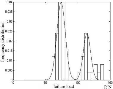
Table 3Limit strains in the studied materials
Type resistor or compound | Limit stresses , MPа | |
Tensile | Compressive | |
Resistor OMLT-0,125 | 68.72 | 500 |
Compound EZK-25 | 108.00 | 110 |
4. The optimization of tolerances
Further, the task of optimizing the value of tolerances for physical and mechanical properties of materials and the geometry of the composite resistor-compound structure is solved. In other words, it is solved what tolerances of physical and mechanical properties of the model Eq. (1) must be in place in order to provide guaranteed structural strength of the resistor sealed with the compound.
Once ceramic and compound materials behave like fragile materials at low temperatures, according to the theory of strength of the first inner and outer cylinders, respectively (Fig. 3), the strength condition yields:
where is contact pressure of Eq. (2); , are the maximum stress in the material of inner and outer cylinders; , are allowable stress values for ceramics and compounds, respectively, and are based on the experimental boundary stresses (Table 3), taking into account the safety factor :
Based on Eq. (8) and Eq. (9), restrictions on output characteristics of the construction are as follows:
In addition, taking technical specifications into account, the primary limiting factors in the model as a system of inequalities read:
Further, the following numerical analysis is carried out. By sorting a large number (105) of values of in predefined intervals Eq. (11), values of maximum operating stress are obtained for ceramic resistors.
Fig. 5Distribution of maximum performance stresses 1 taking into account technical specifications and acceptable stresses 2 for ceramic resistors to guarantee performance conditions Eq. (10)
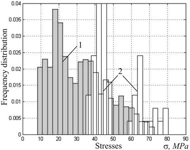
Fig. 5 demonstrates normalized histograms of the distribution of maximum acceptable defined specifications Eq. (11) and stresses for ceramic resistors Eq. (10). Obviously, the constraints Eq. (11) do not guarantee the structural strength of the resistor-compound if tolerances of primary parameters are not justified. More generally, the task for the assignment of tolerances on physical and mechanical properties of materials and the compound resistor as well as the geometric dimensions of the study design can be formulated as follows. For given nominal values of primary factors determine such tolerances (1, 2,…, 9) from nominal values, so that the resulting parallelepiped fulfill the conditions Eq. (8):
The solution to the problem above means that the parallelepiped is entered in the curved region with given inequalities Eq. (8). However, an infinitely large number of such parallelepipeds can be entered. In order to select a particular parallelepiped, it is necessary to impose an additional condition. Therefore an introduction of an optimality criterion is offered (economic, industrial, or any other).
Setting an optimality criterion allows to reduce the problem of determining the tolerances to the problem of optimizing the chosen objective function under constraints Eq. (8).
Since for economic reasons it is desirable to maximize the tolerances on all parameters, the considered optimization problem is multi-objective and a set of optimal values of tolerances can be found by minimizing such objective functions as:
Achieving a simultaneous maximization of all tolerances so that the conditions Eq. (8) are met would be impossible [12].
One solution is to reduce this problem to a one-criterion (scalarization) [13, 14], which is why the linear convolution of the criteria form and Germeier convolution are used, where are normalized positive numbers defined by industrial or economic reasons. Thus, the problem is reduced to determining the values of , at which the maximum of one of the objective functions , , subject to the constraints Eq. (8) with a difference of temperatures between –20 °C tо –60 °C is reached.
The review of these constraints at every step of the optimization process takes place at the vertices of parallelepipeds. They are constructed as partial derivatives of equivalent stresses for each of the primary factors.
The tolerances of physical-mechanical characteristics and geometric dimensions of the construction of the materials and the resistor compound are determined. Restrictions on the primary inputs and output characteristics of the structure are defined by the system of inequalities Eq. (11).
The resulting maximization objective functions and value tolerances allowed determining the meanings of physical and mechanical characteristics of materials and compounding resistor as well as the geometric dimensions of structures in which the conditions of strength are satisfied. These values as primary factors resulting in different sets of coefficients are shown in Table 4. Moreover, in one case mentioned, are set by an expert, and in another, all adopt equal to 1/9 in order to study the case when all the particular criteria are equivalent. Since both methods give similar results of optimization, the usefulness of scalarization of solutions for the vector optimization problem Eq. (13) can be concluded.
Table 4The set of values of boundaries of primary factors
The primary factors | The criterion of optimality | |||||||||
1/9. 1, 2,…, 9 | 0.17; 0.04; 0.08; 0.14 | 1/9. 1, 2,…, 9 | 0.17; 0.04; 0.08; 0.14 | |||||||
Limit values set | Limit values set | |||||||||
Lower | Upper | Lower | Upper | Lower | Upper | Lower | Upper | |||
, degree-1 | 5.5 | 6.5 | 5.5 | 6.5 | 5.5 | 6.5 | 5.5 | 6.5 | ||
, degree-1 | 38 | 42 | 38 | 42 | 38.7 | 41.3 | 38.3 | 41.7 | ||
0.290 | 0.294 | 0.290 | 0.294 | 0.290 | 0.294 | 0.290 | 0.294 | |||
0.315 | 0.345 | 0.315 | 0.345 | 0.322 | 0.338 | 0.321 | 0.339 | |||
, MPa | 1.22 | 1.40 | 1.22 | 1.40 | 1.22 | 1.40 | 1.22 | 1.40 | ||
, MPa | 0.090 | 0.110 | 0.098 | 0.102 | 0.095 | 0.105 | 0.096 | 0.104 | ||
, m | 0.190 | 0.210 | 0.190 | 0.210 | 0.191 | 0.209 | 1.191 | 0.209 | ||
, m | 0.740 | 0.760 | 0.740 | 0.760 | 0.743 | 0.757 | 0.742 | 0.758 | ||
, m | 1.380 | 1.720 | 1.100 | 2.000 | 1.115 | 1.985 | 1.115 | 1.985 | ||
Thus tolerances on physical and mechanical properties of materials as well as geometric dimensions of the axisymmetric composite resistor-compound construction (which ensures the strength of structural elements) are given in the Table 4.
Optimization methods allow specifying tolerances based on primary parameters of the model. In practice, this means that the identified physical-mechanical characteristics of batches of resistors and compounds should be selected in those tolerances.
Global optimization methods [15] can be also used to optimize the tolerances of the primary factors.
5. Conclusions
1. The method for the calculation and testing of physical and mechanical properties of composite ceramic compounds is developed.
2. The value of the developed identification method is the allowance of accurate determination of physical and mechanical properties of a particular batch of a ceramic material. Any mathematical model of the real product contains various assumptions. Substituting it with inaccurate coefficients can compromise even the most accurate calculation scheme. The proposed identification method contributes to the effectiveness of the offered mathematical model.
3. The proposed method is also applicable in case the probability distribution does not obey the laws of the unimodal distribution.
4. The problem of optimizing the tolerances of physical and mechanical properties of materials and geometric dimensions of the composite resistor-compound construction, which ensure the strength of structural elements, is solved.
References
-
Morozov D. I., Andreev P. G., Naumova I. Y. Protecting electronic equipment from the effects of climatic factors. BBK 3243 P 45. 2011, p. 255.
-
Matisen R. L. On the Reliability of Aeroelectric Equipment. Acta et Comm. Univ., Tartuensis 1984, p. 63-66, (in Russian).
-
Herrera-Franco P. J., Valadez-Gonzalez A. A study of the mechanical properties of short natural-fiber reinforced composites. Composites Part B, Engineering, Vol. 36, Issue 8, 2005, p. 597-608.
-
Lokoschenko А. М., Petraschuk S. А., Royzman V. P. Evaluating and ensuring the strength of the system of electronic element-compound. Journal of Khmelnytskyi National University, No. 5, 2012, p. 193-197, (in Ukrainian).
-
Gebali F. Solving Systems of Linear Equations, in Algorithms and Parallel Computing. John Wiley & Sons, Hoboken, NJ, USA, p. 305-321.
-
Lord R. E., Kowalik J. S., Kumar S. P. Solving linear algebraic equations on an MIMD computer. Journal of the ACM, Vol. 30, Issue 1, 1983, p. 103-117.
-
Kershaw D. S. The incomplete Cholesky – conjugate gradient method for the iterative solution of systems of linear equations. Journal of Computational Physics, Vol. 26, Issue 1, 1978, p. 43-65.
-
Andrushevsky N. M. The analysis of the stability of solutions of systems of linear algebraic equations: the manual. Department of the Faculty of Moscow State University named after MV University, MAKS Press, 2008, p. 71.
-
Matsevity Y. M. Inverse heat conduction problem. National Academy of Sciences of Ukraine, Institute of Problems of Mechanical Engineering, 2003.
-
Gądek-Moszczak A., Pietraszek J. On the use of empirical likelihood-based spread regression in the case of flywheel assembly. 3rd International Conference on Engineering Optimization, Rio de Janeiro, Brazil, 2012.
-
Goroshko A. V., Royzman V. P. Presentation and processing of statistical data not subject to the unimodal laws of distribution. Mechanical Engineering and Engineering Education, No. 3, 2013, p. 56-77.
-
Min Yoon, Yeboon Yun, Hirotaka Nakayama Sequential Approximate Multiobjective Optimization Using Computational Intelligence. Springer, 2009.
-
E.Zitzler. Evolutionary algorithms for multiobjective optimization: Methods and applications. Ithaca, Shaker, 1999, p. 63.
-
Sawaragi Y., Nakayama H., Tanino T. Theory of multiobjective optimization. New York, Academic press, 1985, p. 176.
-
Shary S. P. Solving the linear interval tolerance problem. Mathematics and Computers in Simulation, Vol. 39, Issue 1, 1995, p. 53-85.
About this article
This research was done with support of the European Social Fund under the Project “In-Smart” (Agreement No. VP1-3.1-SMM-10-V-02 012).
