Abstract
In order to investigate the nonlinear characteristics of gear transmission system under the action of external and internal excitations, a dynamic model of a spur gear pair was established involving the backlash, damping, transmission error and the meshing stiffness. Based on the incremental harmonic balance method (IHBM), the general forms of the periodic solution with arbitrary precision are deduced. The vibration response obtained by IHBM compare very well with the results obtained by New-Mark method, which verifies the accuracy and electiveness of the analytical methodology (IHBM) and provide information on the dynamic characteristic of spur gear. The simulation results revealed that several types of steady-state periodic solution are identified and determined by employing the IHBM. Due to the effect of backlash, the nonlinear characteristics of jump discontinuity phenomena and multiple stable solutions coexist and the meshing impact phenomenon are obvious. In addition, the influences of the system damping, transmission error and excitation amplitude on the amplitude frequency characteristic are illustrated by a series of diagrams. The results implicate that increasing the external excitation amplitude and system damping can effectively decrease the system resonant amplitude and control the nonlinear vibration response of the gear system and the effect of hardening spring behavior becomes weaker. The transmission error excitation amplitude variation also tends to worse the degree of nonlinearity. Therefore, it presents some useful information to reduce the vibration and noise of gear system.
1. Introduction
It is well known that the gear mechanisms have the advantages of wide range power, high torque to weight ratios, high reliability and stationarity, high transmission efficiency, and accurate drive ratio. Therefore, in the manufacture of industrial rotational machinery, gear transmission systems have been widely used in various applications such as wind turbines, ships, automobiles, and aircrafts. However, the special geometrical characteristics of the gear systems affect the dynamics and vibrational behavior in a significant way. The dynamic analysis of gear system is essential in describing noise and vibration characteristics. Due to the spur gear meshing, the system has different vibration characteristics to compare with simplified rotor system. Therefore, it is important to establish an accurate model for dynamic characteristics of the gear transmission system. In recent year, many researches have been reported on the dynamic models to analyze the dynamic characteristics of gear systems. As a consequence, research in the area of dynamics of mechanical system involving gear mechanisms has been intensified. A number of models were proposed in past to describe the dynamic behavior of gear system [1-4]. Ozguven [5] has comprehensively reviewed the mathematical models and dynamic phenomena in gear dynamics, where the focus was mainly on linear case. Chen [6] developed a nonlinear dynamic model of spur gear pair system with consideration of time-varying mesh stiffness and backlash, which was solved using the numerical method. Ma [7] established a general total degree of freedom dynamic model of a helical gear pair by considering the static transmission error and geometric eccentricities of the gears, and the system was simulated by using beam element and the gear pair by using mesh stiffness matrix and damping matrix.
With the development of nonlinear dynamics, some special issues for nonlinear of gear system will arise from numerical method. Therefore, special measures and small step size are needed which make parametric studies extremely expensive. The IHBM is a powerful approach, which is able to deal with strongly nonlinear system to any desired accuracy, and it is ideally suited to large range parametric studies [8]. A. Kaharman and R. Singh [9] studied the nonlinear dynamic characteristics of spur gear system with the harmonic balance method (HBM). In order to further study the nonlinear characteristics of gear transmission system, A. Kaharman [10] deduced the nonlinear dynamic equation of spur gear rotor system and the influences of various parameters were studied, which solved the nonlinear dynamic response of spur gear system with HBM and Runge-Kutta. Due to the effect of time-varying mesh stiffness, A. Kaharman [11-12] sequentially analyzed the influence of the gear rotor-bearing system with the backlash and the time-varying meshing stiffness, and carried on a detailed analysis to the nonlinear system. Zhang [13] performed dynamic analysis on gear system with the effect of time-varying mesh stiffness and friction between tooth pairs by HBM. In addition, the results obtained by HBM method compare very well with the results obtained by numerical integration method. Raghothama [14] investigated the periodic motions of a nonlinear geared rotor-bearing system by the IHBM. A single degree of freedom model was proposed which included non-linearities associated with periodic time-varying stiffness, backlash and viscous damping between a spur gear pair. Several key issues such as non-linear modal interactions and differences between internal static transmission error excitation and external torque excitation were discussed by Li [15]. Shen [16-19] comprehensively studied the periodic response of a single degree of freedom spur gear model with/without static transmission error by using IHBM, and demonstrated the effectiveness of increasing the damping coefficient ratio or excitation amplitude as a means of controlling the dynamics of the system. Yang [20] established a right-angle gear pair nonlinear time-varying dynamic model by considering both backlash and asymmetric mesh effects and the dynamic response was obtained using an enhanced multi-term harmonic balance method. It can be seen from foregoing literature that there are numerous studies on the topic, but the shafts and bearings are considered as rigid and actually vibration forms are negligible in a spur gear pait system. Due to the reduction of vibration and noise is still one of the issues in spur gear design, it is essential to accurately represent the different components of the gear system, so the relevant parameters ruling system’s dynamic behavior could be identified.
In this paper, considering the complex nonlinear vibration characteristic, an analytical model considered in the following sections proposes a spur gear pair that belongs to a partial of wind turbine gearbox, which can study the vibration characteristics of gear system systematically. And the present work investigates the complex, nonlinear dynamic behaviors of the system by discussing the influence of the system damping, the static transmission error and the excitation amplitude parameters on the periodic motions are illustrated by a series of response diagrams.
2. Dynamic model and equations of motion
2.1. Dynamic model of a spur gear
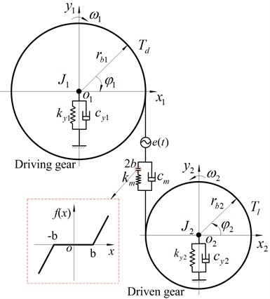
A simplified two-degree-of-freedom purely torsional generalized lumped parameter model of the spur gear transmission system investigated in the present study is shown in Fig. 1. Due to the effects of backlash, relevant parametric excitation and forced excitation, the gear system is a strongly nonlinear system. The shafts and bearings are considered as corresponding stiffness and damping. In addition, the centers of both gears are not allowed to move laterally. The mesh coupling between the driving and driven gears is represented using a set of mesh stiffness and a constant mesh damping elements acting along in the direction of the gear mesh line of action. In addition, backlash nonlinearity and static transmission error are also included.
In order to keep the model formulations at a manageable level, it is assumed that the meshing line direction is -direction in coordinate system in Fig. 1. and are the center of driving and driven gears. The torsional angular displacement of gear is assumed to result from a constant angular velocity term ( 1, 2) plus a small variation displacement due to vibrations originating from the flexibility of the mating gear teeth. Therefore, the angle displacements of the driving and driven gears can be expressed by the following equations:
where and are the constant angular velocity components of the driving and driven gears.
Fig. 1Two degrees of freedom torsional dynamic model of spur gear system
2.2. Equations of motion
According to the previous geometrical relationships, as shown in Fig. 1, a displacement vector of a spur gear pair can be defined from the pressure line co-ordinate system. So the generalized deformation vector can be expressed as follows:
From the proposed concept, taking into the mesh torque, input/output torque. In addition, the displacement force relation at the bearings is taken as linear in this paper. The kinetic energy , the potential energy and the dissipation function are established. Utilizing the Lagrange equation, the equation of two-degree-of-freedom torsional motion of the nonlinear gear system can be expressed as:
where, and are the polar mass moment of inertias; the number of overdots represents the order of differentiation with respect to time ; ( 1, 2) is the torsional displacement of the driving/driven gear; and represent the base radii of gears, and are the mesh stiffness and mesh damping; and indicate the stiffness and damping of bearing; , are the torque applied on driving and driven gears; is a nonlinear displacement function of the dynamic transmission error and static transmission error , which represents geometrical errors of the teeth profile and spacing. The dynamic transmission error and the new define variables can be expressed as follow:
while the nonlinear displacement function is defined as:
where, and stand for the mean and fluctuation; is the gear meshing frequency, and , is the initial phase of transmission error; and are rotational speed of gears; integer and represent the teeth number of driving and driven gears.
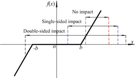
The backlash nonlinearity function and illustration of impact is shown in Fig. 2, which presents three possible impacts, such as no impact, single-sided impact and double-sided impact.
Fig. 2Nonlinear displacement function
For simplicity, to derive the dimensionless equation of gear transmission system, the following transformation parameters are applied:
where, is a characteristic length, is the coefficient of error fluctuation amplitude.
Therefore, nondimensionalized form of Eq. (3) is obtained by considering the foregoing manipulation:
where, is the coefficient of excitationr fluctuation amplitude, and is the system damping coefficient.
3. Incremental harmonic balance method for MDOF gear system
For the multiple degrees of freedom (MDOF) gear transmission system, the generalized nonlinear equations can be written as follows:
where, , , are mass, linear viscous damping and linear stiffness matrices of gear system, respectively; is a nonlinear force; is the degrees of freedom vector of the gear system; represents the number of the degrees of freedom; is the external excitation of the gear system.
In this paper, efforts are devoted to the application of the IHBM to a multi-degree of freedom (MDOF) nonlinear gear system. So , and the Eq. (9) can be expressed as follows:
where, is the excitation frequency (minimum rotational frequency) of gear system; the dots denote derivatives with respect to the dimensionless time .
Using the Netwon-Raphson procedure of the IHBM. Letting , denote a state of vibration in hand, the neighboring state can be expressed by adding the corresponding increments to them as follows:
where, ; .
If the gear system concerned is rotational frequency, meshing frequency, combinatorial frequency and so on. The steady state response can be expressed as follows [12]:
where, is the sum of order harmonic terms:
Substituting Eq. (12) into Eq. (11), the vector of the gear system can be expressed as follows:
where:
Substituting Eq. (13) into Eq. (10) and neglecting small terms of high order, one obtains the following equation:
where, , , and are the Jacobian matrixes.
Using the Galerkin procedure gives:
Substituting Eq. (13) into Eq. (15) and simplified by:
According to the variational characteristics, the Eq. (16) can be expressed as follow:
Therefore, a set linear equations in terms of and can be obtained readily:
where:
4. The validation of analytical methods
From the previous conclusion and analysis, it can be seen that the spur gear pair is a complicated system with the strong nonlinearity, time variance and complicated working environment. Therefore, it is necessary to give a detailed analysis of the gear system. The dynamic behaviors of system are investigated by IHBM. In this paper, Table 1 summarizes the geometrical and physical parameters of a spur gear pair.
Table 1System parameters of gear transmission
Case study | Driving/driven gear | Case study | Driving/driven gear |
Number of teeth | 20 | Meshing stiffness | 5.0×10⁸ N/m |
Module | 10 mm | Meshing damping | 8.0×10² N/(m/s) |
Moment of inertia | 0.05 kg.m2 | Error mean | 2.0×10⁻⁵ m |
Radius | 0.1 m | Error fluctuation | 3.0×10⁻⁵ m |
Torsional stiffness | 4.0×10⁶ N.m/rad | Torque mean | 100 N/m |
Torsional damping | 5.0×10² N/(rad/s) | Torque fluctuation | 300 N/m |
In order to demonstrate the effectiveness and accuracy of the IHBM, the nonlinear dynamic response characteristics of the spur gear pair are obtained by adopting the IHBM and numerical integration New-Mark method (NMM). The time-domain waveforms of the two-degree-of-freedom spur gear system in this study are shown in Fig. 3, where the circle denotes the steady state calculation results by the IHBM and the solid line denotes stable solutions by the NMM, respectively.
Fig. 3Time-domain waveform of the spur gear system
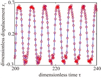
a)
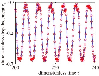
b)
As shown in Fig. 3, it is indicated that the result by IHBM agrees with the NMM’s, which verifies the precision of the IHBM presented in this paper to have high enough. In addition, it takes 300 cycles and 78.84 s, when the gear system closes to steady state response of convergence by NMM. However, the IHBM only needs 13.51 s, which also demonstrate the effectiveness of the IHBM presented in this paper to have a significant advantage.
5. Nonlinear dynamic response of gear system
In this section, the influence of the backlash, the transmission error and the external excitation amplitude parameters on the periodic motions are investigated to detailedly understand the effects of key parameters on the gear dynamical response by a series of response diagrams.
5.1. The jump discontinuity phenomena and multiple stable solutions
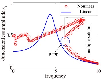
The nonlinear dynamic characteristics of the gear system are detailedly obtained by the IHBM. Due to the driving gear and driven gear have the same geometrical parameters, one of the gear vibration response characteristics is given in this paper. The amplitude frequency characteristic curves of gear transmission system are shown in Fig. 4, where the circle denotes the amplitude frequency curve with considering the backlash ( 0) and the solid line denotes amplitude frequency curve without considering the backlash ( 0) by the IHBM. It can be seen from Fig. 4 that the gear transmission system is a strongly nonlinear system with the influence of backlash factor. There are obviously typical nonlinear characteristics between approximately linear system (0) and nonlinear system ( 0), and the gear system presents hardening spring behavior. As a consequence, the amplitude frequency curve in the solution branches, multiple stable solutions may coexist, making possible the appearance of classical jump discontinuity phenomena with the frequency sweeping. In addition, it appears resonance characteristics close-by the natural frequency and the response amplitude increases slightly.
Fig. 4Jump discontinuity phenomena and multiple stable solutions
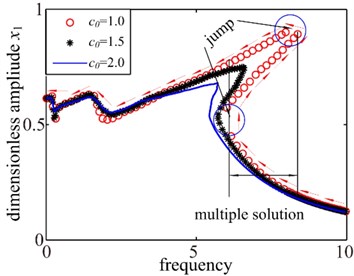
5.2. Effect of system damping coefficient
System damping coefficient is an important parameter that it affects the frequency response substantially. To illustrate this point, in this section, it keeps other parameters constant and only change the system damping coefficient The effect of system damping coefficient on bifurcation diagram and amplitude frequency curves are shown in Fig. 5. It can be seen from the bifurcation diagram that the dynamic behavior of the spur gear system performs chaotic at low values of the system damping coefficient 0.96. At higher values of the dimensionless system damping coefficient, i.e. 0.95, that the motion state of the system mainly shows quasi-periodic motion state. But when the dimensionless system damping coefficient 2.0, the system has a change trend to 1T-periodic motion. It can be noted from Fig. 5(b) that the gear system shows the rich nonlinear behaviors including obvious jump discontinuities phenomena and multiple stable solutions respectively. When the system damping coefficient is small, it can be found the amplitude of response increase and two jump discontinuities are seen coupled with single-sided impact and double-sided impact. In addition, the system exhibits hardening spring behavior due to contact. As the system damping coefficient increase, the nonlinear characteristic of jump discontinuity phenomena is disappearing and further increase of will decrease the response amplitude and multiple stable solutions withdraw gradually, which makes the vibration response behavior more linearly. In addition, the large amplitude of the primary resonance frequency is decreasing and the effect of hardening spring becomes weaker. Therefore, the effect of backlash nonlinearity can decrease with the increasing system damping coefficient .
Fig. 5Dynamics response of system damping coefficient
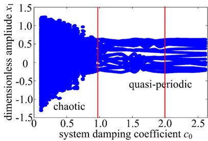
a)
b)
5.3. Effect of static transmission error
The transmission error is a displacement excitation at the mesh point due to the geometrical error of the teeth profile and spacing, which not only affects the response amplitude of the system, but also directly affects the degree of nonlinearity. To examine the effect of transmission error on the frequency response, in this section, the bifurcation diagram with the changing transmission error coefficient is shown in Fig. 6(a). And three different values of the transmission error coefficient are investigated and the results are shown in Fig. 6(b).
Fig. 6Dynamics response of system with changing meshing error
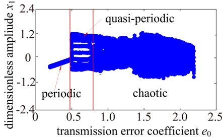
a)
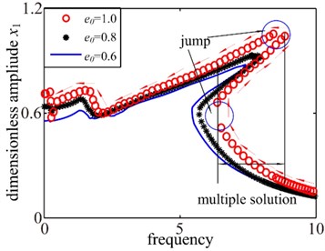
b)
It can be seen from Fig. 6(a) that the gear system exhibits 1T-periodic motion at low values of the dimensionless transmission error , i.e., 0.48. At higher values of the transmission error coefficient , i.e. 0.480.79, that the motion state of the system mainly shows quasi-periodic motion state. However, as is increased, the T-periodic motion is replaced by non-periodic motion. As shown in Fig. 6(b), when the transmission error coefficient is larger, the system clearly performs hardening spring behavior, multiple stable solutions and jump discontinuity phenomena when the gear pair undergoes the transition from single-sided impact to double-sided impact behaviors with the frequency sweping down. However, it can be seen that the jump discontinuity phenomena, tooth impact behavior and multiple stable solutions are gradually disappearing with the decreasing of the transmission error coefficient . In addition, the response amplitude also decreases. Hence, it should reduce the gear transmission error between gears in manufacturing and design phase of gear, which could decrease vibration and noise of gear transmission system.
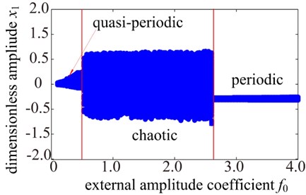
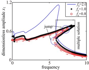
5.4. Effect of external excitation amplitude
In this analysis, only the effect of the external excitation amplitude is analyzed and the other parameters remain the same. The bifurcation diagram and the amplitude frequency curves are shown in Fig. 7. Fig. 7(a) presents the bifurcation diagram of the spur gear system using the dimensionless external excitation amplitude as a bifurcation parameter. A transition from periodic motion to the chaotic dynamic are seen when is increase from 0 to 2.68. It can be observed from Fig. 7(a) that the gear system exhibits a quasi-periodic response at low values of the external excitation amplitude, i.e., 0.5. However, as is increase from 0.5 to 2.68, the quasi-periodic response is replaced by chaotic motion. As the control parameter is further increased, i.e. 2.68, the chaotic motion transits to 1T-periodic motion. Fig. 7(b) presents the results for the spur system with three different values of the external excitation amplitude parameter . As the increases, significant changes in the amplitude frequency curves are observed. When the is relatively small values (i.e. light load), the gear system gradually transition between no impact, single-sided impact and double-sided impact with the frequency sweeping respectively. In addition, the amplitude frequency curves exhibit strongly hardening spring behavior and the response amplitude smaller. As the amplitude of external excitation parameter increases (i.e. heavy load), the single-sided impact and double-sided impact gradually withdraw. Namely, the jump discontinuity phenomena and multiple stable solutions also disappear gradually. When the amplitude of excitation parameter increases to a certain value, the characteristics of gear system response approximate to a linear system and there is no jump discontinuity phenomena seen in the case at all, but the response amplitude increases obviously. Therefore, it is concluded that increasing the amplitude of external excitation can effectively control the nonlinear dynamic response characteristics of the gear transmission system. However, the external excitation amplitude should be limited in a certain scope because of its dual character.
Fig. 7Dynamics response of system with changing excitation amplitude
a)
b)
6. Conclusions
The nonlinear dynamic characteristic of a spur gear pair is studied considering parametrically excited and piecewise linear of two degrees of freedom system that includes the backlash nonlinearity, static transmission error and external excitation. The amplitude frequency characteristic analysis is carried out by the IHBM under a complex dynamical condition. The system shows nonlinear resonances with hardening behavior, jump and multiplicity. Based on the results of the parametric study presented in the previous section, the conclusions can be summarized as follows:
1) Due to the effects of the backlash and the internal and external excitations, the gear system exists obviously typical nonlinear characteristics with hardening spring behavior, jump discontinuity phenomena, such as single-sided impact, double-sided impact, and multiple stable solutions and then the gear pair system can also exhibit more complicated dynamic response.
2) The effect of the system damping parameter is verified that an increase in its value causes a decrease in the amplitude of the solution and the jump discontinuities phenomena and multiple stable solutions withdraw gradually. In addition, the large amplitude of the primary resonance frequency is decreasing and the hardening spring behavior will fade away gradually. Error excitation amplitude variation also tends to worse the degree of nonlinearity, i.e. the nonlinear characteristics are more and more obvious by increasing the error excitation amplitude and the response amplitude increases slightly. The effect of hardening spring behavior gradually strengthens. The unpredictable nonlinear characteristics of jump and multiplicity shoule be avoided in the actual engineering, so it try to increase the system damping system and decrease the installation error and manufacture error during the design phase of gear system.
3) The excitation amplitude has different level effects on amplitude frequency characteristics of the system. The jump discontinuity phenomena and multiple stable solutions of the system become very obvious with smaller excitation amplitude. As the increase of excitation amplitude, the double-sided impact and single-sided impact are disappearing gradually. i.e. nonlinear characteristic becomes weaker, but the response amplitude increases obviously. Therefore, the excitation amplitude should be limited in a certain scope because of its dual character and then preferably control of the dynamic characteristic of gear transmission system.
4) Increasing load, systen dmping and decreasing the error can reduce the amplitude of vibration, the increased complexity of the dynamical behaviour with a spur gear suggests further studies. In particular, a global optimization of gear should be developed in order to suggest the best geometry of spur gears versus vibration reduction.
References
-
Li R. F., Wang J. J. Gear System Dynamics: Vibration, Impact, Noise. Beijing, Science Press, 1997, p. 1-3, (in Chinese).
-
Wojnarowski J., Onishchenko V. Tooth wear effects on spur gear dynamics. Mechanism and Machine Theory, Vol. 38, Issue 2, 2003, p. 161-178.
-
Kuang J. H., Lin A. D. The effect of tooth wear on the vibration spectrum of a spur gear pair. Journal of Vibration and Acoustics, Vol. 123, Issue 3, 2001, p. 311-317.
-
Wang J. J., Li R. F., Peng X.H. Survey of nonlinear vibration of gear transmission system. Applied Mechanics Reviews, Vol. 56, Issue 3, 2003, p. 309-329.
-
Ozguven H. N., Houser D. R. Mathematical models used in gear dynamics-a review. Journal of Sound and Vibration, Vol. 121, Issue 3, 1988, p. 383-411.
-
Chen H. T., Wu X. L., Qin D. T., et al. Dynamic characteristics of gear transmission system subjected to random internal and external excitation. China Mechanical Engineering, Vol. 24, Issue 4, 2013, p. 233-537, (in Chinese).
-
Ma H., Wang Q. B., Huang J. Vibration response analysis of gear coupled rotor system considering geometric eccentric effect of helical gears. Journal of Aerospace Power, Vol. 28, 2013, p. 16-24, (in Chinese).
-
Zhou J. X., Zhang L. Incremental harmonic balance method for predicting amplitudes of a multi-d.o.f. non-linear wheel shimmy system with combined Coulomb and quadratic damping. Journal of Sound and Vibration, Vol. 279, Issue 12, 2005, p. 403-416.
-
Kahraman A., Singh R. Nonlinear dynamic of a spur gear pair. Journal of Sound and Vibration, Vol. 142, Issue 1, 1990, p. 49-75.
-
Kahraman A., Singh R. Nonlinear dynamic of geared rotor-bearing system with multiple clearances. Journal of Sound and Vibration, Vol. 144, Issue 3, 1991, p. 469-506.
-
Kahraman A., Singh R. Interactions between time-varying mesh stiffness and clearance nonlinear in a geared system. Journal of Sound and Vibration, Vol. 146, Issue 1, 1991, p. 135-156.
-
Blankenship G. W., Kahraman A. Steady state forced response of a mechanical oscillator with combined parametric excitation and clearance type nonlinearity. Journal of Sound and Vibration, Vol. 185, Issue 5, 1995, p. 743-756.
-
Zhang S. H., Li Y. P., Qiu D. M. Dynamic analysis of a rotor-bearing system geared by means of the harmonic balance method. Chinese Journal of Mechanical Engineering, Vol. 36, Issue 7, 2000, p. 18-22, (in Chinese).
-
Raghothama A., Narayana S. Bifurcation and chaos in geared rotor bearing system by incremental harmonic balance method. Journal of Sound and Vibration, Vol. 226, Issue 3, 1999, p. 469-492.
-
Li Y. G., Chen T. N., Wang X. P., et al. Nonlinear dynamics of spur gear pair under external periodic excitation. Journal of Xi’An Jiao Tong University, Vol. 24, Issue 4, 2013, p. 233-537, (in Chinese).
-
Yang S. P., Shen Y. J., Liu X. D. Nonlinear dynamics of gear system based on incremental harmonic balance method. Journal of Vibration and Shock, Vol. 24, Issue 3, 2005, p. 40-43, (in Chinese).
-
Shen Y. J., Yang S. P., Liu X. D. Nonlinear dynamics of a spur gear pair with time-varying stiffness and backlash based on incremental harmonic balance method. International Journal of Mechanical Sciences, Vol. 48, Issue 8, 2006, p. 1256-1263.
-
Shen Y. J., Yang S. P, Pan C. Z., et al. Nonlinear dynamics of a spur gear pair with time-varying stiffness and backlash. Journal of Low Frequency Noise, Vibration and Active Control, Vol. 23, Issue 3, 2004, p. 178-187, (in Chinese).
-
Shen Y. J., Yang S. P, Pan C. Z., etc. Nonlinear dynamics of a spur gear pair to parametric and external excitations. Journal of Beijing Jiaotong University, Vol. 29, Issue 1, 2005, p. 69-73, (in Chinese).
-
Yang J. Y., Peng T., Lim T. C. An enhanced multi-term harmonic balance solution for nonlinear period-one dynamic motions in right-angle gear pairs. Nonlinear Dynamics, Vol. 67, Issue 3, 2012, p. 1053-1065.
About this article
The project was supported by China Natural Science Funds (No. 51305276) and the Fundamental Research Funds for the Central Universities (No. N120403004).
