Abstract
Smart structures gain increasingly amount of attention in the past few years with the development of actuator and sensor technology, as well as real time and FPGA controllers. Piezoelectric strip transducers are very suitable for flexible beam structures due to their design and performances. Smart beam modeling is essential for analyses of the dynamic behavior of the beam, but simplified models are necessary for advanced model based control algorithms. In this paper few different approaches in analytical modeling of a smart beam are presented, as well as the methodology of experimental modeling. Data acquisitions guidelines and experimental models derived in LabVIEW are presented. All models are derived and verified on a laboratory experimental setup consisting of aluminum cantilever beam with a pair of collocated piezoelectric transducers.
1. Introduction
A smart beam can be defined as a structure that can sense external disturbance and respond to it actively by previously designed control algorithm in order to keep its dynamics within the desired levels. Smart beams consist of distributed active devices like sensors and actuators that may either be embedded or attached to the structure supported by a powerful controller unit. Measurable parameters like strain, displacement, velocity or acceleration are the commonly fed signals.
The application range of smart beams extends with the commercial availability of sensors and actuators that could be embedded or bonded to the structure without changing the structure dynamics. Smart structures are widely used in place of the traditional structures on account of their ability to adapt according to the current disturbances. From airplane wings, and helicopter blades, over car chassis and windows, to tennis rackets and skis, smart beams are researched extensively and their application area expands.
Piezoelectrics are the most popular smart materials [1]. Good reliability, near linear response to the applied voltage and exhibition of excellent response to the applied electric field over very large range of frequencies coupled with low cost of PZT makes it a very popular choice as a sensor and actuator that enables the structure to be smart. Based on their characteristics, they are used for application in vibration control of flexible structures [2]. Piezoelectric patches are very suitable for bonding on a surface of a beam, without major change in the beam dynamics. From the theoretical aspects, research is still open for the analytical treatment of damping and hysteresis, as well as ways to improve the accuracy of identified mode shapes, in order to improve experimental modeling approach [3]. The author in [4] described two approaches to problem of active damping of vibrations of cantilever beam, the first one uses standard linear time invariant mathematical model of the system, and the second one is based on experimental identification of the first mode shape and design dynamic compensator. The developments in piezoelectric materials have motivated many researchers to work in the field of smart structures [5-11]. Developments in real time and FPGA controllers have also supported this field of research. Software platforms offering numerical modeling, simulation, and system identification are great aid to researchers in completing the research tasks. The author of [12] presents active vibration control of cantilever beam running on general purpose operating system with the LabVIEW platform.
This paper gives direction for analytical modeling of a smart beam derived on a experimental set up of an aluminum cantilever beam with a pair of collocated piezoelectric patches bonded towards the clamed end. The same system was modeled experimentally using the methodology of system identification. The identified model could be used for validation of the analytical model or for a controller design directly. The work was completed with the support from the LabVIEW platform, unifying all phases of the laboratory experiment, form modeling and simulation, to data acquisition and system identification.
Understanding the smart beams dynamic behavior and modeling is essential for development of smart beams. Smart beams’ application are expanding, and our lab research is focused on model based vibration control. The models derived analytically and experimentally are later used for controllers development for real-time and FPGA platforms. The smart structures concept for model based vibration control is planned to be used for stabilization of a digital camera support, mounted on an indoor autonomous vehicle. The autonomous vehicle is programmed to move on predefined coordinates and security check the indoor facility. The vehicle is supposed to occasionally take photos of the surrounding while moving around. The digital camera is mounted on a cantilever beam structure in order to have better view for taking photos. The vibrations cause by the movement of the vehicle can lower the quality of the photos taken by the digital camera, and with model based control the idea is to damp the vibration as much as possible, to obtain better quality photos.
This paper is organized as follows. The next section focuses on smart beams with piezoelectric patches in general and gives details about the cantilever beam used in the experiment. In section 3 the analytical modeling is presented, whereas section 4 focuses on the experimental modeling. Section 5 is conclusion and remarks for future work in this research area.
2. Piezoelectric laminate beam
Smart beam system enables the structure to respond simultaneously to external stimulus exerted on it and then suppress undesired effects or enhance desired effects. Recent advancements in production technologies and electronics among other fields, have given rise to alternate solution in the form of a smart structure to the field of vibrations suppression without significant increase of the overall weight of the equipment. The smart beam being able to suppress vibration by itself, using sensors, actuators and a controller, defines the structure as an active vibration control system. Smart structures are gaining popularity among the interdisciplinary research community because of the availability of smart materials commercially and advances in microelectronics, information processing and sensor technology. Key elements in the application of smart structures technology to a system are actuators, sensors, control methodology and power electronics.
Piezoelectrics undergo deformation (strain) when an electric field is applied across them, and conversely produce voltage when strain is applied, and thus can be both sensors and actuators. Under and applied field these materials generate a very low strain but cover a wide range of actuation frequency. One of the most widely used types of piezoceramics in smart beams is lead zirconate titanate (PZT) in the form of thin sheets as patches bonded to the flexible metal structure. The patches could be distributed along the beam in collocated or noncollacted way. PZT transducers include other positive characteristics such as sensitivity to temperature, fracture toughness, repeatability and reliability, weight density, compactness, heat generation, and efficiency.
A configuration of a smart beam of interest in this paper is a cantilever beam with collocated pair of piezoelectric transducers presented in Fig. 1. Piezo patches are glued on the supporting structure and become part of the structure itself. Piezoelectric sensors operate using the direct effect of the piezoelectric materials, i.e., electric charge is generated when a piezoelectric material is stressed causing deformation. These sensors are extremely sensitive, have superior signal-to-noise ratio, and high frequency noise rejection. Typical piezoelectric actuators operate using the converse effect of piezoelectric materials. This effect states that when a piezoelectric material is placed into an electric field i.e., a voltage is applied across its electrodes; a strain is induced in the material.
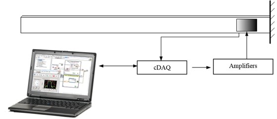
The cantilever beam is made from aluminum with dimensions: length 880 mm, height 35 mm and width 2 mm. The sensing and actuation are done by a pair of piezoelectric transducers applied in collocated way. The piezoelectric patches are glued at the clamped end of the beam on both sides, whereas one is used in sensor mode and the other one is used as an actuator. With their compact design, and thickness of only 0,5 mm, the piezo PI 876 A-12 DuraAct transducers are suitable for integration in the structure itself. To drive the piezo elements in actuator mode high voltage amplifiers are necessary, and here the E-413.D2 amplifiers are installed. For data acquisition a cDAQ chassis module with analog input and analog output cards is used. The acquisition scheme of the system is given in Fig. 2.
Fig. 1Aluminum beam with piezo patches
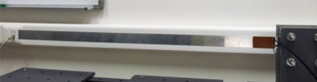
Fig. 2Schematic diagram of the smart beam
The sensor signal extends the analog input card input range, so a voltage divider was introduced to the signal. Voltage divider is simple linear electronic circuit used to lower the voltage of the sensor signal. This voltage divider was made with only 3 standard resistors. The voltage divider secures the voltage range within the limits, and its value is . The actuation requires the amplification form the high voltage amplifiers, and there is also possibility to acquire the actuation signal and monitor it. This monitor signal was used later on for stimulus signal acquisition, for the experimental modeling of the smart beam, in detail presented in section 4.
Table 1Equipment specification
Equipment | Description |
Piezo-Patches, 2 pcs | PI 876 A-12; Range: –100V to +400V |
High voltage amplifiers | E-413.D2; Range: –2.8 V / –100..400V |
Acquisition chassis | NI cDAQ 9174 4 slots, USB chassis |
DAQ cards | NI 9201 AI card ±10 V input range; 500 kS/s sampling rate; 8 channles NI 9263 AO card ±10 V ouput range; 100 kS/s sampling rate; 4 channels |
The equipment specifications used for the complete mechatronic system for active vibration control is given in Table 1.
The smart beam is mounted in a cantilever beam configuration so that the beam’s own weight has minimal influence on the vibration, which means that the vibration of interest is in horizontal plane. The beam behavior was analyzed in different regimes, free and forced vibrations, with different initial conditions.
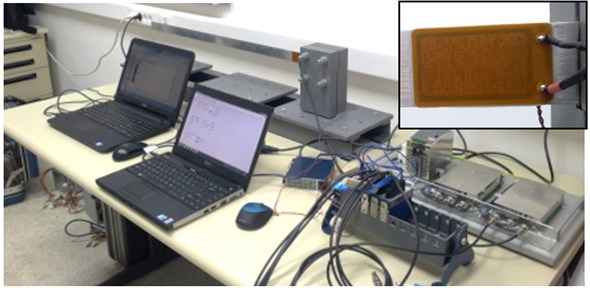
The supporting equipment, such as the amplifiers and the acquisition chassis, as well as the software support on a laptop is presented in Fig. 3.
Fig. 3Smart beam with the support electronic equipment
3. Analytical modeling of a smart beam
Obtaining accurate model of the smart beam is very important task, in the process of smart beam analyses. The smart beam usually runs by a model based control algorithm that requires a model that fits good enough, but is also simple enough to run on a controller unit.
The dynamics of one smart beam in general, for a collocated configuration of piezoelectric transducers Fig. 4 is explained in short here. For details refer to [2].
Fig. 4Smart beam with number of collocated piezoelectric actuator/sensor pairs [2]
![Smart beam with number of collocated piezoelectric actuator/sensor pairs [2]](https://static-01.extrica.com/articles/15309/15309-img4.jpg)
It is assumed that the beam has a length of , width of , and thickness . Corresponding dimensions of each piezoelectric transducer are , , and . It is denoted that the transverse deflection of the beam at point and time is by . Since the beam dynamics depends on two variables, time and coordinate, the dynamic of such structure is governed partial differential equation, known as Euler-Bernoulli theory:
where , , , and represent density, cross-sectional area, Young’s modulus of elasticity and moment of inertia about the neutral axis of the beam respectively.
The total moment acting on the beam is represented by which is the sum of moments exerted on the beam by each actuator, i.e.:
The moment exerted on the beam by the th actuator, can be written as:
where represents the unit step function, i.e.:
The term is incorporated into account for the spatial placement of the th actuator.
The constant can be determined from the ratio of stress distribution along the beam thickness.
The amount of free strain of the actuator is:
where is the amount of free strain of the actuator, is the voltage applied to the piezo element in the direction of the polarization vector, is the piezoelectric constant (the ratio of the strain in the 1 axis to the electric field applied along the 3 axis, when all external stresses are held constant), and is the thickness of the piezoelectric actuator.
Since the piezoelectric patch is bonded to the beam, its movements are constrained by the stiffness of the beam. In these analyses perfect bonding of the actuator to the beam is assumed. Assuming that the strain distribution is linear across the thickness of the beam, the strain distribution throughout the beam and the piezoelectric patches is:
The stress distribution diagram is given in Fig. 5.
Fig. 5Beam with a pair of identical collocated piezoelectric actuators [2]
![Beam with a pair of identical collocated piezoelectric actuators [2]](https://static-01.extrica.com/articles/15309/15309-img5.jpg)
The induced moment intensity in the beam is determined by integrating the stress distribution across the beam:
With proper mathematical derivation and taking into account the natural damping associated with the beam, the differential equation is:
where 1, 2,… and is the generalized coordinate of the th mode, is a parameter that includes length differences among the patches along the length of the beam.
Taking in consideration all the above assumptions, the solution of the main partial differential equation is assumed to be of the form:
where , known as the modeshape, is the eigenfunction which is determined from the eqigenvalue problem based on the specific boundary conditions (e.g. simply supported, cantilevered).
In the dynamics of a smart flexible beam, the first few mode shapes influence the most beam’s dynamic behavior. In this direction and considering the fact that the model is usually used in control algorithm only the first few modes are of interest, since they contribute the most to the system dynamics. In real controller implementation the number of modes is directly connected to the power of the controller, so in this paper we took in consideration all eigen frequencies below 100 Hz, which turns out to be the first 4 modes. The first four eigen frequencies of the cantilever beam of interest in this experiment are 2,1 Hz, 14,7 Hz, 38,3 Hz, and 73,4 Hz.
The corresponding mode shapes are given in Fig. 6.
Fig. 6Mode shapes
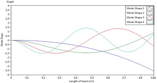
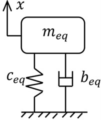
Fig. 7Single degree of freedom model
For many real engineering applications, it is sufficient to use simpler models for dynamic analyses and control of vibrations, so different simplifications could be implemented, for example using finite element modeling and model reductions.
The simplest model for description of the dynamic beam behavior is the single degree of freedom model, where the beam is represented by a standard mass-string-damper model Fig. 7. With such approximation only the first resonant frequency can be modeled and obtained, which can be enough for many applications. Considering the fact the first eigen frequency is the most dominant, in some vibration control cases for smart beams, this model is sufficient.
The mathematical equation for the one degree of freedom model is:
where the equivalent stiffness is equivalent mass is and equivalent damping is obtained experimentally for the beam of interest.
Based on the single degree of freedom model (mass-spring-damper representation), a simulation of the system behavior has been performed in the LabView Control Design and Simulation toolkit. The response of mass position is accordingly scaled in order to be comparable to the voltage representation of the sensor signal.
In Fig. 8 is given the mass displacement of a single degree of freedom model due to non zero initial conditions (the mass initial position is non zero).
Fig. 8Mass position free response
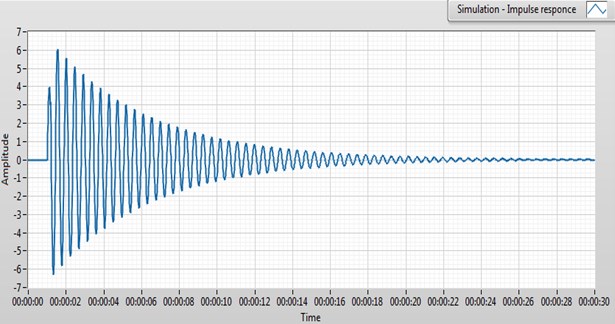
One of the piezoelectric patches is used as a sensor and the beam behavior measured and recorded is given in Fig. 9. The beam vibrations were performed by giving an initial displacement of the free beam end.
This model fits the beam behavior in the parameters as amplitude and settling time quite well, compared between the Figs. 8 and 9. This type of comparison is used as a methodology for model validation. For simple analyses or applications where only the first dominant frequency is of interest, this single degree of freedom analyses is very easy to use. This model is easily transformed in SISO (single input single output) system, presented in transfer function or state space model form, and the transformation are shown in [2].
Fig. 9Sensor signal to a free response
4. Experimental modeling of a smart beam
System identification of a smart beam is often used as a validation step of the analytical model or as a modeling step by itself when an accurate analytical model is difficult to obtain. Analytical models fail when the smart beam becomes complex, like for example the geometry of the beam is not simple to describe or the model needs to describe not ideal boundary conditions of the beam. System identification is the experimental determination of the temporal behavior of a system using measured signals and estimation within a class of mathematical models [7]. The error (respectively deviation) between the real system and its mathematical representation should be as small as possible. The measured signals are typically the input in the system and the output from the system. The identification techniques also have limitations as the currently available system identification algorithms work well only for low-order systems and systems with nicely separated modes.
Measurements for experimental modeling are usually planned based on the purpose and the system analyses prior the measurement itself, which means defining the: input signals (shape, amplitude, frequency); sampling time; measurement time; online or offline identification; real-time or not; necessary equipment; filtering; limitation imposed by actuators (saturation) and others.
The methodology of system identification was applied to the smart beam used in the experiment with the support of System Identification Toolkit within LabVIEW. The first part of the experimental modeling is the data acquisition task.
The most frequently used input signals in vibration system is white Gaussian noise signal and some specified signals such as the chirp signal (signal with a constant amplitude while the frequency changes from low to high limit in a given time), and pseudo random binary signal (signal with two levels changing in a random but repeatable fashion). All mentioned input signals were applied to the actuator piezo patch, and the signal from the sensor patch, as well as the actuation signal were recorded for a total of 100 sec for each input signal. The acquisition was performed with a sampling rate of 1000 Hz.
A number of preprocessing techniques ensure that the incoming data samples are free from external noise, scaling problems, outliers, and other corruptions. These preprocessing techniques include the following methods: visually inspecting data, removing offsets and trends, removing outliers, filtering and down sampling. The data was down sampled with a factor of 50, which makes it enough for the first 100 Hz. Validating the quality of the data at each step in the preprocessing procedure is important in ensuring that is accurately identified a model in later steps of the system identification process.
When the data is collected, appropriate technique for identification is applied. The two most common methods to estimate models are nonparametric estimation and parametric estimation. The impulse response and frequency response are two ways of estimating a nonparametric model. The frequency response reveals the frequency-domain properties, such as the natural frequency of a dynamic system. Nonparametric model estimation is simple and more efficient, but often less accurate, than parametric estimation. Parametric models describe systems in terms of differential equations and transfer functions. Compared to nonparametric models, parametric models provide more insight into the physics of the system and are a more compact model structure. Usually parametric models are divided in two categories: polynomial and state-space. The polynomial model includes AR, ARX, ARMAX, output-error, Box-Jenkins, and general-linear models.
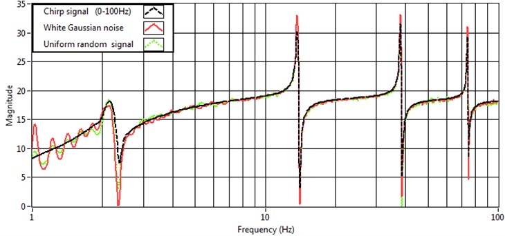
Since the smart beam is a system with infinite number of degrees of freedom, here is presented the frequency response. The frequency estimate of the recorded data was derived for all 3 input signals (the chirp signal with amplitude 2 V and range from 0 to 200 Hz in 100 s; the white Gaussian noise; and the uniform random binary signal. The identification was performed with the support of System identification toolkit from LabVIEW and the frequency estimate of all 3 different sets of stimulus and response data are given in Fig. 10. All different input signals disturb the first 4 eigen frequencies of the structure, and the picks in the graph show the values of the eigen frequencies. These frequencies match the analytically derived ones in section 3.
For the experimental setup used in this research, experimental modeling was performed to derive a state space model, which could be later used for control algorithms of the smart beam. The state space model was determined to be with an optimal number of states 8, which fits perfectly the 4 eigen modes in the range of interest up to 100 Hz. The state space model has state variables, twice the number of eigen frequencies considered.
Fig. 10Frequency estimate
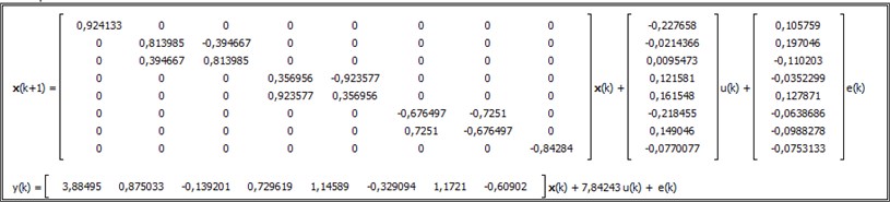
The discrete time state space model, derived from the Gaussian noise stimulus signal and the appropriate sensor signal acquired, is presented in Fig. 11. This model could be transformed later into continuous model for dynamic analyses and controller design, and could be used for controller deployment as it is in discrete time.
Fig. 11State space model
The final step in system identification is model validation, where the model is compared to the system behavior. The state space model was validated with simulation, where the models response was compared with measured system response on different test signals, and showed very good behavior.
5. Conclusions
Presented work focuses on modeling of smart beams with piezoelectric actuators. Mathematical modeling aspects of smart beams with embedded piezoelectric patches are based on the Euler-Bernoulli beam theory. The solution of partial differential equations gives the information about the eigen frequencies and the mode shapes of the beam structure, considered necessary for understanding and analyses of the dynamic system behavior. The simplest mathematical model of a flexible structure is the single degree of freedom, mass spring damper model, and has been derived and validated for the beam of interest.
Developing tools and software support for system identification has gained a lot of interest in the research community of structural mechanics. Analytical models for complex system are difficult to construct based on the many additional elements on the beam in the goal of making it smart. Imperfect boundary conditions are also challenging to take into mathematical consideration in the model. For such cases when the beam is already constructed the methodology for experimental modeling could be applies with great success. In this paper, experimental modeling of the smart beam has been performed with different stimulus signals and the frequency responses were compared, all of them showing the eigen frequencies in the range of 100 Hz. The state space model obtained from the system identification was validated and will be used in control algorithms for vibration suppression of the smart beam.
References
-
Chopra I. Review of state of art of smart structures and integrated systems. AIAA Journal, Vol. 40, Issue 11, 2002.
-
Moheimani S. O. R., Fleming A. J. Piezoelectric Transducers for Vibration Control and Damping. Springer, 2006.
-
Alvin K. F., Robertson A. N., Reich G. W., Park K. C. Structural system identification: from reality to models. Computers and Structures, Vol. 81, 2003.
-
Kovářová J., Schlegel M., Dupal J. Vibration control of cantilever beam. Journal of Vibroengineering, Vol. 9, Issue 2, 2007, p. 45-48.
-
Moheimani S. O. R., Vautier B. J. G. Resonant control of structural vibration using charge-driven piezo electric actuators. IEEE Transactions of Control System Technology, Vol. 13, Issue 6, 2005, p. 1021-1035.
-
Fei J., Fang Y. Active feedback vibration suppression of a flexible steel cantilever beam using smart materials. 1st International Conference on Innovative Computing, Information and Control, 2006, p. 89-92.
-
Hu H., Suxiang Q., Linfang Q. Self sensing piezoelectric actuator for active vibration control based on adaptive filter. International Conference on Mechatronics and Automation, 2007, p. 2564-2569.
-
Manning W. J., Plummer A. R., Levesley M. C. Vibration control of a flexible beam with integrated actuators and sensors. Smart Materials and Structures, Vol. 9, Issue 6, 2000, p. 932-939.
-
Gaudenzi P., Benzi R. Control of beam vibrations by means of piezoelectric devices: theory and experiments. Composites and Structures, Vol. 50, Issue 4, 2000, p. 373-379.
-
Vasques C. M. A., Rodrigues J. D. Active vibration control of smart piezoelectric beams: comparison of classical and optimal feedback control strategies. Computers and Structures, Vol. 84, Issues 22-23, 2006, p. 1402-1414.
-
Fei J. Active vibration control of a flexible structure using piezoceramic actuators. Sensors and Transducers Journal, Vol. 89, Issue 3, 2008, p. 52-60.
-
Parameswaran A. P., Pai A. B., Tripathi P. K., Gangadharan K. V. Active vibration control of a smart cantilever beam on general purpose operating system. Defence Science Journal, Vol. 63, Issue 4, 2013, p. 413-417.
About this article
