Abstract
The geogrid reinforced soil retaining wall is a flexible retaining wall. It will produce large deformations during earthquakes, especially on liquefied backfill soils. An index of liquefaction extent is applied to express the effect of excess pore water pressure in reinforced backfill sand during earthquakes. A geogrid reinforced soil retaining wall is represented by an isotropic vertical elastic beam. The calculation method of the seismic residual deformation of the geogrid reinforced soil retaining wall is based on the Rayleigh-Ritz method and the the Mononobe-Okabe pseudo-static method. The effect of liquefaction extent in the backfill sand is studied for seismic active earth pressures acting on a reinforced wall back and seismic residual deformations of a reinforced wall. Some influence parameters on seismic residual deformations of geogrid reinforced soil retaining walls are investigated in detail, such as the internal friction angles in the backfill sand, friction angles of the wall, horizontal seismic intensities, reinforcement length of the geogrid and soil properties. Finally, the calculated results are compared with test results of a model on large-scale shaking table. The conclusions about the parameters will be helpful for seismic designs of geo-grid reinforced soil retaining walls on liquefied foundations. The proposed pseudo-static calculation method can be used to predict safe seismic deformations of geogrid reinforced soil retaining walls.
1. Introduction
Compared with gravity retaining walls, the geogrid-reinforced wall is a relatively flexible retaining wall, and it will produce large deformations, especially on liquefied backfill soils. To ensure deformations do not affect normal uses of a retaining wall, the horizontal deformation of a geogrid reinforced soil retaining wall must be controlled within a reasonable range.
A few researchers have studied theoretical deformations of geogrid reinforced soil retaining walls. Based on the experimental data of reinforced earth retaining walls, Yang Ming [1] used the Newmark sliding block model to account for the dynamic behavior of the reinforced earth retaining walls. The formulation of yield acceleration of the reinforced earth retaining walls was given by the upper bound method of limit analysis. Sensitivity analysis showed that the yield acceleration of reinforced earth retaining walls was significantly affected by the wall geometry as well as the strength of the soil and reinforcements. The conclusions were consistent and could be the foundation of a displacement-controlled design method of reinforced earth retaining walls. Guangqing Yang [2] proposed a new method of calculating the horizontal deformation of reinforced retaining walls, which assumed that the reinforced soil retaining wall acted as a coherent block, similar to a conventional retaining wall under horizontal earth pressure from backfill material. The reinforced soil retaining wall was assumed to be an equivalent anisotropic elastic medium, and all the elastic properties were derived. When calculating the horizontal deformation of the reinforced soil retaining wall, the reinforced soil block was assumed to be a cantilever beam. The horizontal deformation of cantilever beam was calculated for pure bending and pure shear modes.
If a reinforced retaining wall is backfilled with cohesive soil, excess hydrostatic pressure may be induced under certain conditions. The excess hydrostatic pressure has influence on the potential failure surface in the backfill, as well as on the soil pressure and its distribution. The Rankine’s theory can be used for the pore water pressure in one dimensional state. It cannot be used in two-dimensional state. A graphical analysis method is proposed by Guangxin Li (2001) to calculate the soil pressure. The circular slip method is suggested to calculate its safety factor. A retaining wall with positive pressure and a soil nailing system with negative pressure in pit are also discussed. O. Al Hattamleh (2008) presented a membrane analogy method to evaluate the deflection of fabric-reinforced earth walls. The resulting equations were solved using a finite difference scheme to obtain the deflection. The numerical results were compared with a full-scale study. The comparisons show good performance of the model. Syed Mohd. Ahmad (2008) presented a simple design methodology for waterfront reinforced soil-retaining wall by considering both the hydrodynamic pressure and seismic forces acting simultaneously on the wall has been proposed. The seismic forces are calculated using the pseudo-dynamic approach, which considers the velocities of the shear and primary waves propagating through the soil. Limit equilibrium analysis by considering the horizontal slice method has been adopted. Deepankar Choudhury (2010) presents a methodology for seismic design of rigid water front-retaining wall and proposes simple design factors for the sliding stability under seismic condition. Conventional pseudo-static approach has been used for the calculation of the seismic forces, while for the calculation of the hydrodynamic pressure, Westergaard's approach has been used. In addition, the hydrodynamic force has been considered from both the upstream and downstream sides of the waterfront-retaining wall under free water condition of the backfill. Katdare (2012) introduced an attempt that has been made to include Rayleigh wave along with shear and primary waves for calculation of seismic active earth pressure. Syed Mohd. Ahmad (2012) analyzed and designed techniques for reinforced-soil wall situated at the water front and subjected to the earthquake forces. Pseudo-static approach issued for seismic forces in conjunction with the horizontal slice method. The effects of seismic shaking of water on the backfill side (inside the backfill grains) and water on outboard side of the waterfront reinforced-soil wall were considered in the analysis.
El-Emam and Bathurst (2004) provided the experimental design, equipment and instrumentation for a reinforced soil wall response using shaking table. El-Emam and Bathurst (2005) discussed the influence of the facing geometry, the facing mass and the facing toe boundary condition on the wall response. Ling et al. (2005) presented an experimental study of the earthquake performance of modular-block reinforced soil retaining walls which were backfilled with sand using large-scale benchmark shaking table tests. El-Emam and Bathurst (2007) carried out reduced-scale model shaking table tests with rigid facing panels to investigate the reinforcement design parameters. Chen et al. (2007) conducted a series of centrifuge models to simulate a clayey vertical geotextile-reinforced earth wall (VGREW) in a wet state due to the poor drainage conditions that resulted after several consecutive days of heavy rainfall. A series of uniaxial shaking table tests using stepwise intensified sinusoidal waves was performed on plane-strain geosynthetic-reinforced slopes to investigate the effects of wave frequency and amplitude on the seismic displacements and horizontal acceleration response of geosynthetic-reinforced slopes by Huang et al. (2010, 2011). Huang (2013) performed a series of stepwise intensified shaking tests to investigate the vertical acceleration responses at the crest of a reinforced model slope subjected to horizontal input ground excitations.
In this paper, the index of liquefaction extent is applied to express the effect of excess pore water pressure in reinforced backfill sand during earthquake and is applied to deduce calculation methods of dynamic earth pressures and seismic residual deformations of the geogrid reinforced soil retaining wall. Rayleigh method is an important method of energy methods and often is applied to solve deformations of structures in static or dynamic states. In this paper, it is used to solve the static horizontal deformation of vertical reinforced soil retaining walls. Pseudo-static method is a simple method to solve dynamic problems, and it is developed early and is used widely. And based on Mononobe-Okabe pseudo-static method, the calculation method of seismic residual deformation of the geogrid reinforced soil retaining wall will be deduced.
2. Calculation method
2.1. Index of liquefaction extent
During earthquakes, excess pore water pressure in soil can reduce soil strength and make soil soften, and in order to understand it easily for engineering designers, in this paper, the excess pore water pressure is defined as extent of liquefaction(Wang, 2007), which is expressed as:
where is called as extent of liquefaction, is current effective stress, is initial effective stress and is pore water pressure increment.
2.2. Calculation of static horizontal deformation
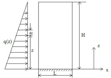
Here, the geogrid reinforced soil retaining wall is assumed to be a vertical elastic beam, and the wall width is assumed as , which is geogrid reinforced length. The wall will generate horizontal displacements under earth pressure of triangular distribution acting on the wall back, which is shown in Fig. 1. According to Rayleigh-Ritz method, the deflection curve of central axis in beam is described as:
where is the deflection displacement at the location of z, , , and are the coefficients of deflection curve formula. The formula need satisfy the following boundary conditions:
thus, and can be achieved, so, the deflection curve becomes:
Considering the triangular distribution of earth pressure acting on the wall back, is defined as the load acting on per unit length, is one unit length, then, the load acting on length is , which is shown in Fig. 1.
Fig. 1The force diagram of reinforced soil retaining wall
When the deflection displacement at the location of is , the work of earth pressure acting on one unit length of wall back is , so, the total work of earth pressure acting on the whole wall back is:
The total strain energy caused by bending of reinforced soil retaining wall is:
where, is the elastic modulus of the geogrid reinforced soil retaining wall, is the inertia moment of the section of reinforced soil retaining wall and it is calculated as:
The derivative of equation (3) is taken with respect to is:
Substituting (7) in (6), then Eq. (6) takes the form:
Substituting (4) in (5), then Eq. (5) takes the form:
where and , and is the earth lateral pressure coefficient, is the unit weight of soil, then Eq. (9) takes the form:
According to the principle of minimum potential energy, and can be confirmed as the following:
where , hence:
Then:
After the integral of Eq. (13), the solution takes the form:
After the integral of Eq. (14), the solution takes the form:
According to Eq. (15) and (16), the solutions of and are:
Substituting (17) in (4), then Eq. (4) takes the form:
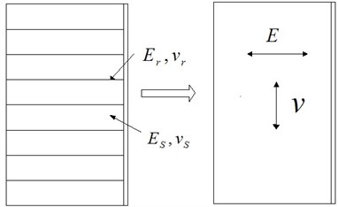
The geogrid reinforced soil retaining wall is assumed to be an isotropic elastic structure, and it is shown in Fig. 2.
Fig. 2Idealized isotropic horizontal system of reinforced soil
Deformations of reinforced wall are caused by pure bending and pure shear, and the horizontal deformation caused by pure shear is:
where is the shear modulus of the reinforced soil retaining wall. So, the deformation caused by pure bending and pure shear is:
Here can be calculated as:
Here can be calculated as:
where is the elastic modulus of geogrid, is Poisson’s ratio of geogrid, is the elastic modulus of soil, is Poisson’s ratio of soil, is the thick of geogrid, is the thick ratio of geogrid and .
2.3. Calculation of seismic residual deformation in liquefied soil
Because Rayleigh method can be applied to solve dynamic deformations of structures, so, based on the above results, seismic residual deformation will be deduced by Mononobe-Okabe pseudo-static method.
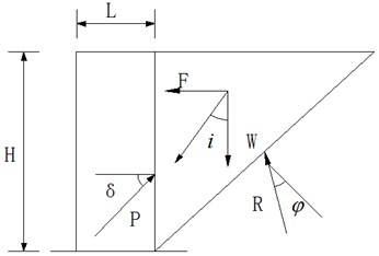
The analysis model of seismic active earth pressure acting on reinforced soil retaining wall is shown in Fig. 3, is horizontal seismic force, is gravity, is seismic inertia angle and , is seismic earth pressure and is reaction force.
Fig. 3The diagram of seismic active earth pressure acting on reinforced soil retaining wall
During earthquakes, seismic earth pressures acting on the wall back will be decreased due to excess pore water pressure in soil, and softened soil will have greater strain, which will bring greater deformation of wall. Hence, the seismic earth pressure considering extent of liquefaction can be expressed as:
where is seismic active earth pressure coefficient, and it is calculated as (Mononobe, 1924; Whitman and Christian, 1990):
where is the friction angle of wall back, is the inertial friction angle of soil.
Substituting (23) in (9), then Eq. (9) takes the form:
Substituting (24) in (11), then according to the above the principle of minimum potential energy, the calculation equation of seismic residual horizontal deformation can be achieved, which is expressed as:
3. Results and discussions
Seismic internal forces of geogrids in reinforced soil retaining wall structures under earthquake actions have been researched by Finite difference method without considering liquefaction extent of backfills (Wang, 2014). The FEM study considering extent of liquefaction is complex and difficult and will be carried out in the future work. In order to research the effects of design parameters and liquefaction extent for seismic residual deformations of geogrid reinforced soil retaining walls, one standard model of geogrid reinforced soil retaining wall is given. The reinforcement height () is 6 m, the reinforcement length () is 6 m, the effective internal friction angle of soil () is 30°, the friction angle between wall back and soil () is 15°, the unit weight of backfill soil () is 19 kN/m3 and the horizontal seismic coefficient () is 0.4. Here, is 100 MPa, is 0.15, is 56 MPa and is 0.25, so, is 56.2 MPa and is 0.25.
3.1. Distribution of dynamic earth pressure
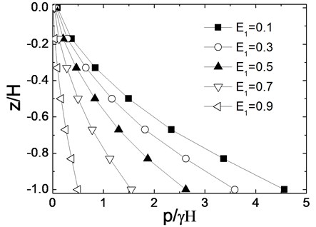
In the pseudo-static calculation method, is a qualitative parameter, so here, is respectively confirmed as 0.1, 0.3, 0.5, 0.7 and 0.9. The calculation results of dynamic earth pressures are shown in Fig. 4. It can be seen that dynamic earth pressures increase with the increase of wall depth. Extent of liquefaction has extinct effects for dynamic earth pressures, and dynamic earth pressures decrease with the increase of , whenincreases respectively from 0.1 to 0.5 and from 0.5 to 0.9, dynamic earth pressures decrease nearly 50 % respectively.
Fig. 4Dynamic earth pressure distribution along wall depth
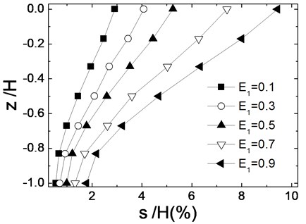
3.2. Distribution of seismic residual deformation
Fig. 5 presents the distribution of seismic residual deformation of reinforced wall under different extent of liquefaction. Extent of liquefaction has extinct effects for seismic deformation, and seismic deformations increase with the increase of . When is larger than 0.5, the reinforced wall has more than 5 % seismic deformations, which indicates that the reinforced wall produces large deformations due to liquefaction of backfill sand and the wall has lost stability.
Fig. 5Seismic residual deformation distribution along wall depth
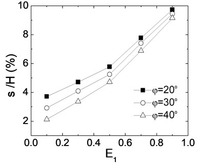
3.3. Effect of inertial friction angles in backfill sand
Fig. 6 gives the relation between seismic residual deformation and extent of liquefaction when inertial friction angles in backfill are respectively 20°, 30° and 40°. Seismic deformations decrease with the increase of inertial friction angles. When is 0.3 and inertial friction angle increase from 20° to 30°, seismic residual deformation decrease 15 %. But when is 0.9 and inertial friction angle increase from 30° to 40°, seismic residual deformation decrease only 3 %. It indicates that the effect of inertial friction angles decrease with the increase of ; when is high and backfill sand becomes soft, the inertial friction angle of backfill soil has little effect for seismic deformation of reinforced soil retaining wall.
Fig. 6Effects of internal friction angle
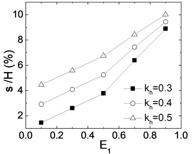
3.4. Effects of horizontal seismic coefficients
Fig. 7 shows the relation between seismic residual deformation and extent of liquefaction when horizontal seismic coefficients are respectively 0.3, 0.4 and 0.5. Seismic deformations increase significantly with the increase of . When is 0.5 and increases from 0.3 to 0.4, seismic deformation increase 50 %, and when is 0.9 and increases from 0.3 to 0.4, seismic deformation increases 19 %. It shows when is high and backfill sand becomes soft, the effect of the horizontal seismic coefficient decrease for seismic deformation of wall.
Fig. 7Effects of horizontal seismic coefficient
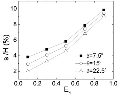
3.5. Effects of wall friction angles
Fig. 8 gives the relation between seismic residual deformation and extent of liquefaction when friction angles between wall and soil are respectively 0.25, 0.5 and 0.75. Because wall friction angles are confirmed by internal friction angles of backfill sand, the calculation results are similar to internal friction angles. Seismic deformations decrease with the increase of wall friction angles and increase with the increase of . When is 0.1 and 35 MPa increases from 7.5° to 15°, seismic deformations decrease 35 %, and when is 0.9 and 35 MPa increases from 7.5° to 15°, seismic deformations decrease 8 %. Hence, when is high, wall friction angles have little effects for seismic deformation of wall.
Fig. 8Effects of wall friction angle
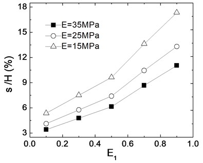
3.6. Effects of soil properties
Fig. 9. presents the relation between seismic residual deformation and extent of liquefaction when elastic modulus of backfill soil is respectively 15 MPa, 25 MPa and 35 MPa. It is shown that seismic deformations decrease with the increase of elastic modulus. When is 0.1 and elastic modulus increases from 25 MPa to 35 MPa, seismic deformations decrease 18 %, and when is 0.9 and elastic modulus increases from 25 MPa to 35 MPa, seismic deformations decrease 22 %. It indicates that when is high, the elastic modulus of soil has great effect for seismic deformation of wall.
Fig. 9Effects of elastic modulus of soil
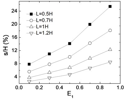
3.7. Effects of reinforcement length
Fig. 10 shows the relation between seismic residual deformation and extent of liquefaction when reinforcement length is respectively 0.5, 0.7, 1.0 and 1.2. Seismic deformations decrease with the increase of reinforcement length. When is 0.1 and reinforcement length increases from 0.7 to 1.0, seismic deformations decrease 33 %, and when is 0.9 and reinforcement length increases from 0.7 to 1.0, seismic deformations decrease 45 %. It indicates that when is high, reinforcement length has great effect for seismic deformation of wall.
Fig. 10Effects of reinforcement length
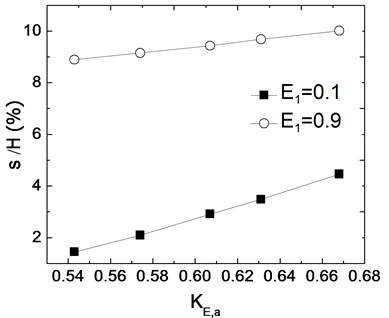
3.8. Relation between seismic deformation and dynamic earth pressure coefficient
The relation between seismic deformation and dynamic earth pressure coefficient is shown in Fig. 11. Seismic deformations increase linearly with the increase of . When is 0.1 and increases from 0.6 to 0.7, seismic deformation increases 100 %; when is 0.9 and increases from 0.6 to 0.7, seismic deformation increases 10 %.It indicates that when is high, the dynamic earth pressure coefficient has little effect for seismic deformation of wall because is a comprehensive index of inertial friction angles and wall friction angles, which have little effect for seismic deformations when is high.
Fig. 11Relations between deformations and dynamic earth pressure coefficients
4. Verification of proposed calculation method
The mesa size of a shaking table was 3.36 m×4.86 m, and the maximum gravity capacity was 25 t, and the maximum horizontal acceleration was ±1.0 g The test model was constructed in the laminar shear container, which was made of 15-layer laminated shear model boxes, and three-direction dimensions were 3.5 m×2.0 m×1.7 m (L×W×H).
In the test model, the dimensions of the rigid walls were 170 cm×70 cm×5 cm (L×W×H), the walls were made up of low intensity concrete and a grade reinforced bar. According to the similitude requirement of , the suitable elastic modulus of 1.6×10⁴ N/mm2 could be achieved, which represented the elastic modulus of 3.2×10⁴ N/mm2 in the prototype concrete. The unit weight of the concrete was about 19 kN/m3.The cohesive subsoil was placed into the bottom of the container to reduce the water penetration from the backfill sand. The backfill soil was derived from Nanjing fine sand. The unit weight of the backfill sand was 14 kN/m3 and the relative density was 55 %. The water table of the backfill sand was 5cm below the ground surface. The length of the reinforced sand was 70 cm. The dimensions of test model are shown in Fig.12. Three laser displacement meters (DH1-DH3) were installed onto one batten and fixed by one steel frame to test the lateral displacements of the walls. Five pore pressure meters were placed into the backfill sand to test excess pore water pressures (W1-1-W1-5). The acceleration recording of ground motion is shown in Fig. 13. Fig. 14 presents time histories of excess pore water pressure ratio () in different positions of the test backfill sand when the ground motion intensity is 0.3 g.
Fig. 12Shaking table test models (dimensions: cm)
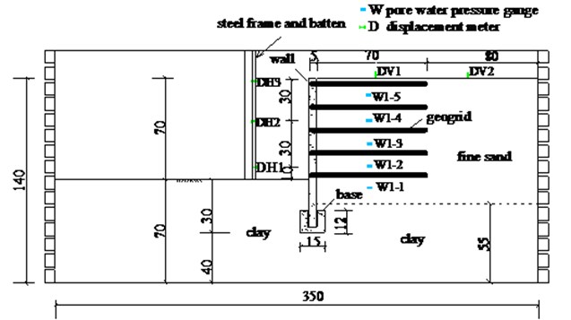
Fig. 13Acceleration recording of ground motion
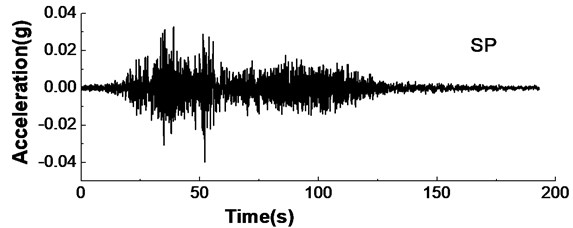
Fig. 14Time histories of excess pore water pressure
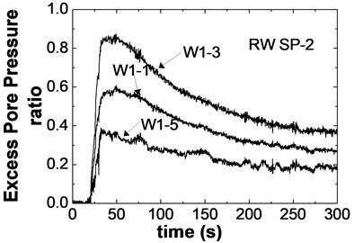
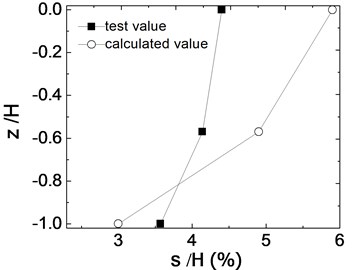
Considering the effect of extent of liquefaction for seismic deformations, average excess pore water pressure ratios are used to calculate the seismic deformation. In the positions of W1-1, W1-3 and W1-5, excess pore water pressure ratios are confirmed respectively as 0.4, 0.6 and 0.2. The calculated results of seismic deformations by the proposed pseudo-static method and test results of maximum seismic deformations are compared. The ratios of maximum seismic deformation (s) and wall height (H) are shown in Fig. 15.
Although the calculated deformation ratio of wall bottom (DH1) of 3 % is a little smaller than the test result of 3.6 %, the calculated deformation ratio of wall top (DH3) is about 5.9 % and larger than the test result of 4.4 %. Similarly, the calculated deformation ratio of wall middle (DH2) is also larger than the test result. The reason that the calculated result of wall bottom is less than test result is that the wall bottom is fixed in the proposed calculation method. However, in deformation designs, the reinforced wall top is important reference part. Therefore, according to the above comparisons, the pseudo-static calculated method is reasonable and can be applied to predict safe seismic deformations of geogrid reinforced soil retaining walls in liquefied foundations.
Fig. 15Comparisons between test results and calculated results
5. Conclusions
The pseudo-static calculation method of seismic deformations of geogrid reinforced soil retaining wall is proposed considering the effects of excess pore water pressure in the paper, and by discussing the effects of some parameters and comparison with test results, some conclusions are achieved as follows:
1) Extent of liquefaction has great effect on dynamic earth pressures and seismic deformations of the reinforced wall. With the increase of extent of liquefaction, dynamic earth pressures decrease and seismic residual deformations increase significantly.
2) Seismic deformations decrease with the increase of internal friction angles in backfill sand and friction angles of wall back, and when extent of liquefaction is high, these friction angles have little effect for seismic deformations.
3) Seismic deformations decrease with the increase of elastic modulus of backfill sand and reinforcement length of geogrid. When extent of liquefaction is high, the elastic modulus and reinforcement length have great effects for seismic deformation of reinforced walls.
4) Seismic deformations increase linearly with the increase of horizontal seismic coefficient. when extent of liquefaction is high, the dynamic earth pressure coefficient has little effect for seismic deformation of wall.
5) The comparison with test results shows the proposed pseudo-static calculated method is reasonable and can be applied to predict safe seismic deformations in the seismic design of geogrid reinforced soil retaining walls in liquefied foundations.
References
-
Yang Ming, Wu Delun, Yan Zhixin Yield acceleration of reinforced earth retaining walls in earthquake analysis. Chinese Journal of Rock Mechanics and Engineering, Vol. 21, Issue 5, 2002.
-
Yang G. Q., Zhou M. J., Zhang B. X. Study on the horizontal deformation of reinforced retaining walls of soils. Chinese Journal of Geotechnical Engineering, Vol. 24, Issue 7, 2005.
-
Li Guangxin, Chen Ping, Jie Yuxin, Wen Qingbo Stability analysis of reinforced retaining wall under excess hydrostatic pressure. China Civil Engineering Journal, Vol. 34, Issue 3, 2001, p. 103-110.
-
Al Hattamle O., Muhunthan B. Numerical procedures for deformation calculations in the reinforced soil walls. Geotextiles and Geomembranes, Vol. 24, 2008, p. 52-57.
-
Syed Mohd. Ahmad, Deepankar Choudhury Pseudo-dynamic approach of seismic design for waterfront reinforced soil-wall. Geotextiles and Geomembranes, Vol. 26, 2008, p. 291-301.
-
Deepankar Choudhury, Syed Mohd. Ahmad Pseudo-static design factors for stability of waterfront-retaining wall during earthquake. Earthquake and Tsunami, Vol. 4, Issue 4, 2010, p. 387-400.
-
Katdare Amey, Choudhury Deepankar Effect of rayleigh wave on seismic active earth pressure behind retaining wall. Disaster Advances, Vol. 5, Issue 4, 2012.
-
Syed Mohd. Ahmad, Deepankar Choudhury Seismic internal stability analysis of waterfront reinforced-soil wall using pseudo-static approach. Ocean Engineering, Vol. 52, 2012, p. 83-90.
-
El-Emam M. M., Bathurst R. J. Experimental design, instrumentation and interpretation of reinforced soil wall response using a shaking table. International Journal of Physical Modeling in Geotechnics, Vol. 4, Issue 4, 2004, p. 13-32.
-
El-Emam M. M., Bathurst R. J. Facing contribution to seismic response of reduced-scale reinforced soil walls. Geosynthetics International, Vol. 12, Issue 5, 2005, p. 215-238.
-
Ling H. I., Mohri Y., Leshchinsky D., Burke C., Matsushima K., Liu H.-B. Large-scale shaking table tests on modular-block reinforced soil retaining walls. Journal of Geotechnical and Geoenvironmental Engineering, Vol. 131, Issue 4, 2005, p. 465-476.
-
El-Emam M. M., Bathurst R. J. Influence of reinforcement parameters on the seismic response of reduced-scale reinforced soil retaining walls. Geotextiles and Geomembranes, Vol. 25, Issue 1, 2007, p. 33-49.
-
Chen H. T., Huang W. Y., Chang C. C., Chen Y. J., Lee C. J. Centrifuge modeling test of a geotextile-reinforced wall with a very wet clayey backfill. Geotextiles and Geomembranes, Vol. 25, Issue 6, 2007, p. 346-359.
-
Huang C.-C., Horng J.-C., Chueh S.-Y., Chiou J.-S., Chen C.-H. Dynamic behavior of reinforced slopes: horizontal acceleration response. Geosynthetics International, Vol. 17, Issue 4, 2010, p. 207-219.
-
Huang C.-C., Horng J.-C., Chueh S.-Y., Chiou J.-S., Chen C.-H. Dynamic behavior of reinforced slopes: horizontal displacement response. Geotextiles and Geomembranes, Vol. 29, 2011, p. 257-267.
-
Huang C. C. Vertical Acceleration response of horizontally excited reinforced walls. Geosynthetics International, Vol. 20, Issue 1, 2013, p. 1-12.
-
Wang Liyan, Liu Hanlong Discussion on assessment of earth-structure liquefaction deformation based on the concept of degree of liquefaction. Journal of Disaster Prevention and Mitigation Engineering, Vol. 27, Issue 4, 2007.
-
Mononobe N. Considerations on vertical earthquake motion and relevant vibration problems. Journal of Japan Society of Civil Engineers, Vol. 10, Issue 5, 1924, p. 1063-1094, (in Japanese).
-
Whitman R. V., Christian J. T. Seismic response of retaining structures. Proceedings of POLA Seismic Workshop on Seismic Engineering, San Francisco, Vol. 3, 1990, p. 533-540.
-
Wang Liyan, Chen Shangkun, Gao Peng Research on seismic internal forces of geogrids in reinforced soil retaining wall structures under earthquake actions. Journal of Vibroengineering, Vol. 16, Issue 4, 2014, p. 2023-2034.
About this article
The authors appreciate the support of National Natural Science Foundation of China (No. 51109099) and National Science Foundation for Post-doctoral Scientists of China (No. 2011M50906).
