Abstract
In this paper, frequencies of low order vertical modals for three-tower self-anchored suspension bridge (TSSB) are studied. The first three-tower self-anchored suspension bridge is taken as prototype in the paper. The finite element model of the bridge is established. And dynamic characteristics are analyzed. Based on Rayleigh method, frequency formulas of 1st asymmetric vertical vibration (AVV) and symmetric vertical vibration (SVV) are deduced considering contribution of towers stiffness. The accuracy of deduced formulas was validated by results of numerical analysis and modal test. Stiffness characteristic difference between TSSB and multi-tower earth-anchored suspension bridge (MESB) is researched based on frequency formulas. The significant difference is gravity stiffness component in frequency formulas. At last, influence law of tower stiffness on vertical frequencies was studied based on validated formulas. The results indicated that: 1) middle tower stiffness and side tower stiffness play important role in frequency of 1st AVV and SVV respectively. Frequencies are enlarging as tower stiffness increasing; 2) when tower stiffness is low, deduced frequency formulas are the same as formulas neglecting influence of tower stiffness in reference paper; 3) based on deduced frequency formulas, expressions of critical tower stiffness for simplified formulas are proposed.
1. Introduction
Three-tower self-anchored suspension bridge (TSSB) is one new kind of bridge, which combines the advantages of self-anchored suspension bridge and three-tower suspension bridge [1, 2]. TSSB is one of the best kinds of bridge for urban medium-span bridge, which has particular adaptability to site of W shape [3]. It has many advantages [4], such as elegant appearance, good site adaptive capacity and relative larger across ability. Louzhou Bridge is the first TSSB, which is built Fuzhou, China, in 2012 [5]. And this kind of bridge can be built more in any place in the world.
As lacking of effective constraints from cables, equivalent stiffness of middle tower in TSSB is low [6]. Therefore, the static and dynamic mechanical properties of three-tower suspension bridge are quite different from traditional double-tower suspension bridge [7]. Among them, free vibration characteristics is quite different. An experiment of scaled multi-tower suspension bridge specimen has been made to study its dynamic characteristics [8]. Jiao (2010) [9] studied dynamic characteristic of Taizhou Bridge, which is a two-span three-tower earth-anchored suspension bridge (TESB). The studied shows that frequency of 1st vertical vibration is 0.08267 Hz, whose modal shape is asymmetric vibration. Related researches show the 1st vertical vibration is usually shown as asymmetric vertical vibration as equivalent stiffness of middle tower is low [10].
Dynamic characteristics of bridge are the base for earthquake and wind resistant design [11, 12]. At present, finite element method (FEM) is widely used in accurate analyzing vibration frequencies and mode shapes. Jiao (2010) [13] established the finite element model of TSSB by ABAQUS and studied effects of elastic restraints between mid-tower and girders on dynamic property of TESB. Wang (2014) [14] developed a three-dimensional finite element model to study the free vibration characteristics of a triple-tower twin-span suspension bridge during the construction phase and right after the erection of the main cable. Wang (2010) [15] studied the dynamic characteristics of the Taizhou Yangtze River Bridge, the first triple-tower long-span suspension bridge in China based on ABAQUS. The results showed the vertical, lateral and torsional stiffness of girder have different effects on the dynamic characteristics of triple-tower suspension bridges. Furthermore, the parametric analysis on the structural flutter stability of Taizhou Yangtze River Bridge was carried out in 2014 [16].
However, there are some disadvantages of FEM, especially on preliminary design phase. For example, it is time-consuming to comparing different design proposals and difficult to reveal influence law of special parameters. In this sense, frequency estimation formulas are fit, as it can quickly provide general frequencies for estimating on preliminary design phase and validating on fine numerical modeling analysis phase [17]. In addition, we can easily get the influence rules of each structure parameter from frequency formulas [18]. Therefore, the frequency formulas are meaningful for quick calculating frequencies. And Chao (2013) [19] deduced frequency formulas of first order vertical modals for TSSB. However, both of them have not considered the effect of tower stiffness on frequencies, which is significant for three-tower suspension bridge in most cases.
In this paper, the frequency estimation formulas of vertical vibration for TSSB considering influence of tower stiffness are deduced by Rayleigh method. Based on deduced formulas, different dynamic mechanical properties between three-tower and double-tower self-anchored suspension bridge are studied based on frequency formulas. And influence law of tower stiffness on vertical frequency is discussed in detail.
2. Typical TSSB description and finite element modeling
2.1. Description of typical TSSB – Louzhou Bridge
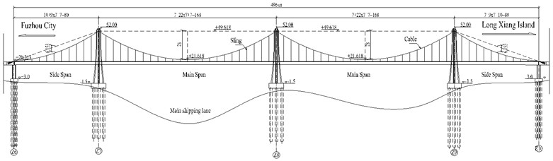
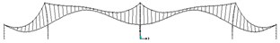
Louzhou Bridge is the first three-tower self-anchored suspension bridge in the world. It is taken as prototype structure of three-tower self-anchored suspension bridge (TSSB) in this paper shown in Fig. 1. This bridge, crossing the Ming River at Fuzhou, China, was opened to traffic in 2012.
The arrangement of the spans along the bridge is 80 m+168 m+168 m+80 m, with an overall length of 496 m. The total width of the bridge deck is 43 m. The suspension bridge system is composed of two sets of suspension cables anchored at the continuous steel deck directly without any anchorage block. Span ratio of main span is 1:6, while that of side span is 1:12.88. The space between slings is 7 m. The deck over the four spans is supported by cables and bearings. Other structural parameters are shown in Table 1.
Table 1Structural parameters of Louzhou Bridge (Unit: m, t, kN)
Parameter | Value | Parameter | Value | Parameter | Value |
6.35 | 50.85 | 1.95E+08 | |||
28.00 | * | 4.33E+04 | 2.06E+08 | ||
80.00 | * | 4.33E+04 | 3.45E+07 | ||
168.00 | 0.73 | * | 0.0474 | ||
103.42 | 33.40 | 1.50 | |||
207.71 | * | 42.10 | 1.69 | ||
Note: 1) , , stand for rise, span, equivalent cable length for side span (middle span) respectively; 2) subscript of , , indicate cable, girder and tower respectively; 3) , , , stand for tower equivalent stiffness, linear mass, elasticity modulus and area respectively; 4) superscript means the value for each one. | |||||
2.2. Finite element modeling
For purposes of this study, a complete 3D FE model was developed in SAP2000N as shown in Fig. 2. This model is used for both static and dynamic analyses. The FE model consists of 1418 nodes and 1664 elements. The bridge towers were represented by three-dimensional multilevel portal frames with the two legs fixed at the base. The soil-structure interaction was not considered in this model.
The geometric properties of three-dimensional beam elements of towers and piers were calculated from design drawings. Since cross sections of tower legs are decreasing from base to top, sectional properties of beam elements for tower were assumed to be uniform section in each 2 m element. Tower equivalent stiffness is 4.33E+04 kN/m shown in Table 1.
Fig. 1Elavation figure of Louzhou Bridge (unit: m)
The equivalent beam was connected to the suspenders through a series of horizontal rigid arm members. The bearings between the deck and the towers were represented as swing rigid links so as to allow free longitudinal motion of the deck. The lateral motion of the deck relative to the towers was restricted through horizontal rigid links.
Fig. 2Louzhou Bridge: a) panorama and b) 3D finite-element model
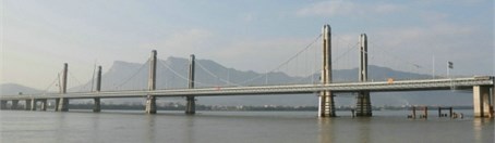
a)
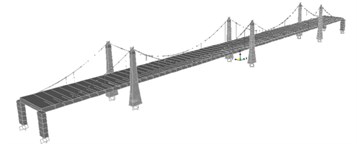
b)
2.3. Modal analysis
Modal analysis is needed to determine the natural frequencies and mode shapes of free vibration. The initial equilibrium configuration is important in suspension bridges since it is a starting position to perform the succeeding analysis [20]. Therefore, the dead load has a significant influence on the stiffness of suspension bridge. In numerical analysis, this influence can be taken into account through the static analysis under the dead load and cable tensions before dynamic analysis is carried out.
Fig. 3Mode shape of 1st AVV
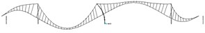
Fig. 4Mode shape of 1st SVV
In this paper, modal analysis is carried out based on static analysis under dead loading and cable pre-tensions. We can get the natural frequencies and mode shapes. In general, modal analysis of the Louzhou Bridge showed the modes were arranged in certain sequence: longitudinal mode, vertical modes, lateral modes and torsion modes. As we mainly concern about the vertical stiffness of TSSB, the first 2 vertical modes and frequencies are shown in Fig. 3 and Fig. 4. The frequencies of the 1st AVV and SVV are 0.4481 Hz and 0.6295 Hz respectively. More information of dynamic characteristics is shown in reference [21].
3. Frequency formulas for vertical vibration
3.1. Rayleigh method
Rayleigh’s method is a technique for finding natural frequencies by equating the maximum kinetic energy of a system with the maximum potential (often strain) energy. Rayleigh’s method is a widely used, classical method for the calculation of the natural vibration frequency of a structure in the low order. According to Rayleigh’s method, we can get the formula as followed:
where, stands for maximal value of gravitational potential energy; stands for maximal value of kinetic energy; is the deformation function of each component; is the quadratic differential form of .
3.2. Frequency formulas and derivation process
Some parameters are defined for simplified expression during the formulas derivation process, shown as followed.
is the length of girder in the th span; is the rise of cable in the th span; is the height of the th tower; is the geometric alignment of cable in the th span, whose expression is ; is geometric parameter of cable in the th span, whose expression is ; is the equivalent longitudinal stiffness of the th tower, whose expression is ; is the vertical deflection of girder in the th span; is the horizontal tensile force of cable in the th span; is the horizontal deflection of top node in the th tower.
As the simplest type of TSSB, the three-tower self-anchored suspension bridge (TSSB) is taken as example in this section. We can get typical model shapes for first 2 orders vertical vibration, shown in Fig. 5 and Fig. 6.
Fig. 5Mode shape of 1st asymmetric vertical vibration
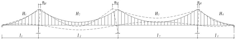
Fig. 6Mode shape of 1st symmetric vertical vibration
Some basic assumptions are adopted in this paper containing the first 6 assumptions in reference [19]. Besides, the influence of tower stiffness to vertical vibration is considered. The deformation shapes of girder and tower for each modal are assumed based on the boundary condition and mode shape. Deformation shapes of girder are same to reference [9]. Deformation shape of tower is assumed as deformation of cantilever column under uniform lateral horizontal force. That is shown as followed:
Based on basic assumptions, we can get vibration energy expressions of each components, such as cables, towers and girders. The expressions of kinetic energy and potential energy are deduced as followed:
Based on force equilibrium and deformation compatibility conditions, the relations between the variables are inferred from above deflection drawing. And expressions of kinetic energy and potential energy for each component of TSSB are obtained. By the Eqs. (1), (3a), (3b), we can deduce the frequency formulas for 1st symmetric and asymmetric vertical vibration as shown in the next section. More details can refer to reference [21] (Zhangchao, 2011).
3.2.1. Frequency formula for 1st asymmetric vertical vibration (AVV)
Frequency of 1st symmetric vertical vibration is named . For symbol , superscript a stands for asymmetric vibration; subscript v stands for vertical vibration; the overline stands for considering the influence of tower stiffness in frequency calculation. We can get formula for frequency shown as followed:
where, is a variable related to lengths of each span; is a variable related to spans, ratio, tensile stiffness of cables and bending stiffness of towers, named Tower Stiffness Influence Coefficient (TSIC) for 1st AVV. Their expressions are shown as followed:
3.2.2. Frequency formula for 1st symmetric vertical vibration (SVV)
Frequency of 1st asymmetric vertical vibration is named . For the symbol , superscript stands for asymmetric vibration; subscript stands for vertical vibration; overline stands for considering the influence of tower stiffness in frequency calculation. We can get the calculation formula for frequency as followed:
where, , are variables related to lengths of each span:
is a variable related to tensile stiffness of cables, compressive stiffness of girder and bending stiffness of towers, named Tower Stiffness Influence Coefficient (TSIC) for 1st symmetric vertical vibration. And , , are some variables related to some structural parameters. Their expressions are shown as followed:
3.3. Frequencise formulas validation
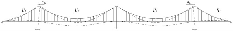
3.3.1. Example of physical scaled model of TSSB
The physical scaled model of TSSB in Reference [1] (Zhang C., et. al) is taken as example. A quite dense measurement location on the bridge deck in the vertical directions was proposed to identify acceptable mode shapes of the bridge in that paper. Stochastic Subspace Identification (SSI) method in the time-domain was implemented to identify the measured acceleration data. The identified most significant vertical frequencies of the TSSB scaled model bridge are summarized in that paper. Among that, frequencies of 1st asymmetric and symmetric vertical vibration are 8.16 Hz and 14.35 Hz respectively.
According to provided structural parameters in Reference [1] (Zhang C., et. al), we can get values of tower equivalent stiffness and equivalent cable length. They are shown as followed: 65.79 kN/m; 2.05 m, 4.15 m.
Therefore, we can calculate the frequencies of first 2 vertical modals for this physical scaled TSSB model by deduced formulas in this paper.
1) calculated by frequency formulas:
From Eq. (5), (6), we can get , ;
Then, according to Eq. (4), we can get 7.9543 Hz.
2) calculated by frequency formulas:
From Eqs. (8), (9), we can get 0.0253; 3.82;
From Eqs. (10), (11), we can get –0.945; –1.031; –4.993; 1.068;
Then, according to Eq. (7), we can get 13.9950 Hz.
The formulas computed result and measured result are shown in Table 2. From the table, we can find that frequency computed from provided formulas are in good agreement with the result in reference [1].
Table 2Frequencies comparison for two TSSB (Unit: Hz)
Modal shape | Physical scaled model of TSSB | Louzhou Bridge | ||||
Experiment measured | Formulas computed | Frequency difference | Experiment measured | Formulas computed | Frequency difference | |
1st AVV | 8.1600 | 7.9543 | –0.2057 | 0.4481 | 0.4578 | 0.0097 |
1st SVV | 14.3500 | 13.995 | –0.3550 | 0.6295 | 0.6298 | 0.0003 |
3.3.2. Example of practical bridge
Louzhou Bridge in section 2 is taken as an example in this part. Structural parameters of Louzhou Bridge are shown in Fig. 1. Based on modal analysis of FEM, natural frequencies of first 2 vertical mode shapes were calculated to be 0.4481 Hz and 0.6295 Hz, shown in Fig. 2 and Fig. 3.
For Louzhou Bridge, we can calculate frequencies of first 2 vertical modals, by deduced formulas in this paper, as followed.
1) calculated by frequency formulas:
From Eqs. (5), (6), we can get , ;
Then, according to Eq. (4), we can get 0.4578 (Hz).
2) calculated by frequency formulas:
From Eqs. (8), (9), we can get ; ;
From Eqs. (10), (11), we can get –0.47; –1.326; –191.81; ;
Then, according to Eq. (7), we can get 0.6298 (Hz).
The frequencies computed by two methods are compared in Table 2. We can come to the conclusion that the results come from deduced formulas are similar to numerical computed.
All in all, frequencies of low order vertical modal of two TSSB are calculated by deduced formulas in this paper. And the accuracy of formulas is validated by results of both experiment test data and numerical analysis result. It is a new frequency calculation method of TSSB, besides finite element method. The deduced formulas are special suitable for preliminary design stage, in which the detailed structural parameters are not sure. Through the formulas, the frequency can be estimated quickly. On the other hand, the computations of this paper can be used to test the correctness of finite element model.
4. Influence law of tower stiffness on frequencies
4.1. Influence law of tower stiffness on frequency
As we can know from above analysis, tower stiffness plays great roles in frequencies. The influence law of tower stiffness on vertical vibration will be studied in this section. Methods of formulas calculation and numerical analysis are used in this study. The structural parameters of Louzhou Bridge shown in Table 1 are taken as fundamental parameters in this section. In parameters analysis, tower stiffness is changed from 0.1 times to 1.5 times.
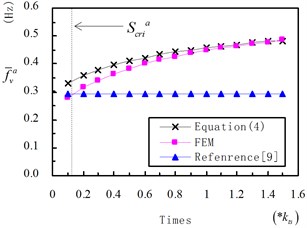
is defined as Tower Stiffness Influence Coefficient for 1stAsymmetric Vertical Vibration (AVV). We can get changing curve of on middle tower stiffness () by Eq. (6) shown in Fig. 9. We can see from Fig. 9, increases from 1.65 to 9.15, as times of is changing from 0.1 to 1.0. When is low, value of is tends to be 0. is influenced significant by stiffness of middle tower . In particular, gradient of become lower as times of enlarge. It discloses that is more sensitive to when is low.
Values of on different are shown in Fig. 10. In the figure, the first line means frequencies calculated Eq. (4) proposed in this paper. The second line means frequencies analyzed by finite element model. And the third line means frequencies calculated by Eq. in reference [9]. As we can see from the figure, frequencies calculated by Eq. (4) and “FEM”, match well in most of time, especially when the time is close to 1. increases from 0.3959 Hz to 0.4578 Hz as is changing from 2.17E+05 kN/m to 4.33E+05 kN/m. The rate of frequency increase is near 15.6 %. The natural frequency enlarges gradually with increasing . The influence law of is similar to in Fig. 9. All in all, enlarging the value of middle tower stiffness is an effective way to improve frequency of 1st AVV.
In Fig. 10, curve of “Reference” shows as a straight line with constant value of 0.2944 Hz, as influence of tower stiffness was ignored in the formula. Comparing curves of Eq. (4) with reference [9], frequency difference is small when is low, while that increases as is enlarging. The difference shows that influence of tower stiffness cannot be ignored if is large. Otherwise, the error will be significant. In other words, contribution of middle tower stiffness is more and more important as tower stiffness increasing.
Fig. 9Value of α on different ktm
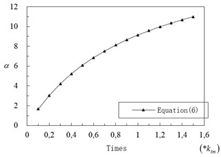
Fig. 10Value of f-va on different ktm
From Eq. (7), we know frequency of 1st SVV () is closely related to side tower stiffness (). Therefore, we study relationship between and in following section.
is defined as tower Stiffness Influence Coefficient for 1st Symmetric Vertical Vibration (SVV). Based on Eq. (10), we can get curve of on different side tower stiffness (), as shown in Fig. 11. We can see from the figure, increases as is enlarging. When is low, value of tends to be 1.
Fig. 11Value of β on different kts
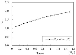
Fig. 12Value of f-vs on different kts
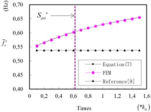
Frequencies of 1st SVV () on different are shown in Fig. 12. As we can see, value of calculated by Eq. (7) and “FEM”, match quite well. Value of increases from 0.5948 Hz to 0.6298 Hz as changing from 2.17E+05 kN/m to 4.33E+05 kN/m. The curve of in Fig. 12 is similar to in Fig. 11.
Frequencies calculated by formula of reference [9] is shown in Fig. 12. Comparing frequencies calculated by Eq. (7) with reference [9], the values are significant different when is large. However, the frequencies tends to be equal when becomes low.
Based on the above conclusion, we can guide for the dynamic design of TSSB. Take seismic performance design of TSSB as example, to avoid predominant period of foundation site and reduce the seismic response, long natural vibration period is expected. Based on the conclusion of this paper, lower longitudinal stiffness of middle tower is designed to reduce frequency of 1st Symmetric Vertical Vibration (SVV). At the same time, from the frequency formulas we can know that minishing mass of girder can prolong natural period too. By the same token, we can easily adjust natural period of TSSB in wind resistant design and vehicle-bridge resonance analysis.
4.2. Comparing to formulas ignoring influence of tower stiffness
In Reference [19], formulas to calculate vertical frequencies were deduced neglecting influence of tower stiffness on vertical vibration, shown in Eqs. (12), (13):
Comparing Eq. (4) and Eq. (7) to reference [9], existing of coefficient and is the only difference between equations. Based on Eq. (5) and Eq. (10), and are mainly related to tower stiffness. Coefficient tends to be 0 when middle tower stiffness is quite low. And coefficient tends to be 1 when side tower stiffness is quite low. Therefore, when tower stiffness is quite low, Eqs. (4) and (7) can be transformed to Eq. (12) and Eq. (13) respectively. In other words, formulas in reference [9] are special forms of deduced formulas in case of low tower stiffness. Therefore, formulas in this paper are unified with that in Reference [9]. We can come to the conclusion that influence of tower stiffness on vertical vibration can be neglect when tower stiffness is low. Eqs. (12) and (13) are suggested to calculate frequency when tower stiffness is low for simplicity.
4.3. Critical tower stiffness for simplified formulas
As shown in above equation, and stand for frequencies considering contribution of tower stiffness. While, and stand for frequencies neglecting contribution of tower stiffness.
We take formulas of and as example. Obviously, the former formulas are excelling in accuracy, while the latter are simpler for calculation. The difference between and comes from whether considering influence of tower stiffness. As the analysis of above section, when tower stiffness is low, the deference value would be limited. In this section, we aim to get a critical tower stiffness . When tower stiffness below , is approximately equal to . In this case, formulas of can be taken to calculate low order vertical frequency more efficiently.
4.3.1. Critical tower stiffness for 1st AVV
is defined as accuracy requirement. In general, is set to be 0.9 in civil engineering. If value of is greater than , can take place of in frequency evaluation. Therefore, we can get following equation:
We can assume stiffness of middle tower is equal to that of side tower . Eqs. (5) and (6) are substituted into Eq. (14). Then the equation can transfer to following form:
That is expression of critical tower stiffness for 1st AVV (). Based on equation, we can make a judgment before calculating frequency. If is below to , it means the error between and is limited. In this case, to simplify the calculation process, we can use Eq. (12) to evaluate frequency of 1st AVV for TSSB.
4.3.2. Critical tower stiffness for 1st SVV
In the same way, we can get expression of critical tower stiffness for 1st SVV (), shown in following:
where:
If is below to , it means the error between and is limited. In this case, to simplify the calculation process, we can use Eq. (13) to evaluate frequency of 1st SVV for TSSB.
We can take Louzhou Bridge in section 2 as example. Based on above Eqs. (15) and (16), we can calculate the critical tower stiffness for 1st AVV and SVV. is set to be 0.9 in calculation, we can get is 5.63×10³ kN/m. for 1st AVV. And is 2.68×10⁴ kN/m for 1st SVV. The values are shown as dotted line in Fig. (10) and Fig. (12) respectively.
5. Comparing to three-tower earth-anchored suspension bridge (TESB)
Three-tower self-anchored suspension bridge (TSSB) is a special kind of bridge, which can be seen to combination of three-tower earth-anchored suspension bridge (TESB) and self-anchored suspension bridge. Therefore, it synthesizes the characters of both. In this section, structural characters of different types of bridge will be studied based on frequency formulas.
Reference [22] has deduced frequency formulas for three-tower earth-anchored suspension bridge, shown in Eqs. (17), (18):
where, , , stand for span, equivalent cable length and rise respectively.
During the derivation of above formulas, influence of tower stiffness on frequencies was ignored. Therefore, to keep formulas comparable between different bridges, Eqs. (12), (13) are selected as contrastive equations.
Besides the same expressions, there are some additional expressions in frequency formulas for MESB. In Eqs. (14), (15), there are additional expressions of and respectively. These components mean gravity stiffness coming from dead load of cable and girder, defined as gravity stiffness component. For cable elements, stress stiffening due to great dead load of girder and cable must be considered, which is defined as effect of stress stiffening. From above formulas, we know that gravity stiffness component plays an important role in vertical stiffness of MESB. Therefore, it can significantly improve vertical frequency of MESB by increasing dead load.
However, that is different for TSSB. As cables being directly anchored to girder, girder is at compression-bending coupling state. For TSSB, effects of stress stiffening and compression-bending coupling are balanced. As a result, there is no gravity stiffness component in frequency formulas for TSSB. Therefore, increasing dead load cannot enlarge vertical stiffness of TSSB. Furthermore, it will increase seismic response of TSSB. This is one of the most significant differences between TSSB and MESB.
6. Conclusions
This paper is focus on frequency calculation method and influence law on frequency for TSSB. The following conclusions have been drawn from this study.
1. The finite model of first three-tower suspension bridge is established. The low order frequencies and modal shape are studied by finite element method.
2. Frequency formulas of 1st vertical AVV and SVV were deduced by Rayleigh method with considering the influence of tower stiffness. The validity of the deduced formulas is verified by results of both numerical analysis and modal test.
3. Stiffness characteristic difference between TSSB and MESB is studied by frequency formulas. The comparison discloses the significant difference is gravity stiffness component in frequency formulas.
4. Influence laws of tower stiffness on structural stiffness are studied by both formula method and finite element method. The research results show that middle tower stiffness and side tower stiffness play important role in frequency of 1st AVV and SVV respectively. Frequencies are enlarging as tower stiffness increasing. When tower stiffness is low, deduced frequency formulas are the same as formulas in other paper without considering influence of tower stiffness. At last, expressions of critical tower stiffness for simplified formulas are deduced based on deduced frequency formulas.
References
-
Zhang C., Fang Z. Shaking table test of multi-tower self-anchored suspension bridge. Applied Mechanics and Materials, Vol. 353-356, 2013, p. 2216-2220.
-
Gimsing N. J., Georgakis C. T. Cable supported bridges: Concept and Design. Third edition, Wiley Online Library, 1983.
-
Forsberg T. Multi-span suspension bridges. Steel Structures, Vol. 1, Issue 1, 2001, p. 63-73.
-
Nazir C. P. Multispan balanced suspension bridge. Journal of Structural Engineering, Vol. 112, Issue 11, 1986, p. 2512-2517.
-
Fang Z. Z., Zhang C. Dynamic characteristics analysis and parametric study of self-anchored suspension bridge with three towers. Journal of Earthquake Engineering and Engineering Vibration, Vol. 36, Issue 4, 2010, p. 97-102, (in Chinese).
-
Yoshida O., Okuda M., Moriya T. Structural characteristics and applicability of Four-Span suspension bridge. Journal of Bridge Engineering, Vol. 9, Issue 5, 2004, p. 454-463.
-
Deng Y. L., He X. J. Seismic vulnerability analysis of long-span multi-tower suspension bridge. International Conference on Computational and Information Science, Chengdu, 2010, p. 458-461.
-
Zhang D., Zhang Y. F. Research on dynamic characteristics model test scheme for middle pylon of multi-pylon multi-span suspension bridges. Engineering Sciences, Vol. 10, Issue 3, 2012, p. 64-71.
-
Jiao C. K., Li A. Q., Cao L. L., Wang H. Traveling wave influence analysis for triple-tower suspension bridges. China Civil Engineering Journal, Vol. 43, Issue 12, 2010, p. 100-106, (in Chinese).
-
Zhang J. W., Guo W. H., Xiang C. Q. Dynamic characteristics analysis and parametric study of a super-long-span triple-tower suspension bridge. Applied Mechanics and Materials, Vol. 256-259, 2013, p. 1627-1634.
-
Arzoumanidis S., Shama A., Ostadan F. Performance-based seismic analysis and design of suspension bridges. Earthquake Engineering and Structural Dynamics, Vol. 34, Issue 4-5, 2005, p. 349-367.
-
Au F. T. K., Cheng Y. S., Cheung Y. K. On the determination of natural frequencies and mode shapes of cable-stayed bridges. Applied Mathematical Modeling, Vol. 25, 2001, p. 1099-1115.
-
Jiao C. K., Li A. Q., Wang H. Analysis on parameters of dynamic property of triple-pylon suspension bridge. Journal of Highway and Transportation Research and Development, Vol. 27, Issue 4, 2010, p. 51-55, (in Chinese).
-
Wang L., Guo X., Noori M., Hua J. Modal analysis of cable-tower system of twin-span suspension bridge. Journal of Vibroengineering, Vol. 16, Issue 4, 2014, p. 1977-1991.
-
Wang H., Zou K., Li A., Jiao C. K. Parameter effects on the dynamic characteristics of a super-long-span triple-tower suspension bridge. Journal of Zhejiang University: Science A, Vol. 11, Issue 5, 2010, p. 305-316.
-
Wang H., Tao T., Zhou R., Hua X., Kareem A. Parameter sensitivity study on flutter stability of a long-span triple-tower suspension bridge. Journal of Wind Engineering and Industrial Aerodynamics, Vol. 128, Issue 03, 2014, p. 12-21.
-
Rossikhin Y. A., Shitikova M. V. Analysis of nonlinear free vibrations of suspension bridges. Journal of Sound and Vibration, Vol. 186, Issue 3, 1995, p. 369-393.
-
Abdel-Ghaffar A. M. Vertical vibration analysis of suspension bridges. Journal of the Structural Division, Vol. 106, Issue 10, 1980, p. 2053-2075.
-
Zhang C. Simplified calculation of primary vertical frequencies for multi-tower self-anchored suspension bridge. Journal of Wuhan University of Technology, Transportation Science and Engineering, Vol. 37, Issue 4, 2013, p. 753-757, (in Chinese).
-
Ren W. X., Peng X. L. Baseline finite element modeling of a large span cable-stayed bridge through field ambient vibration tests. Computers and Structures, Vol. 83, Issue 8, 2005, p. 536-550.
-
Zhang C. Response of self-anchored suspension bridge with three-tower. Fuzhou, Fuzhou University. Doctoral dissertation, 2011, (in Chinese).
-
Liu B. Vibration characteristics research on three-tower suspension bridge. Chengdu, Southwest Jiao Tong University, Doctoral dissertation, 2009, (in Chinese).
About this article
The study was sponsored in part by Research Fund for the Doctoral Program Project of the Ministry of Education (No. 20133514129996) and in part by National Natural Science Foundation of Fujian Province (No. 2013J05072).
