Abstract
In this paper a pre-stack reverse-time migration concept of signal processing techniques is developed and adapted to guided-wave propagation in composite structure for multi-damage imaging by experimental studies. An anisotropic laminated composite plate with a surface-mounted linear piezoelectric ceramic (PZT) disk array is studied as an example. At first, Mindlin Plate Theory is used to model Lamb waves propagating in laminates. The group velocities of flexural waves are also derived from dispersion relations and validated by experiments. Then reconstruct the response wave fields with reflected data collected by the linear PZT array. Reverse-time migration technique is then performed to back-propagate the reflected energy to the damages using a two-dimensional explicit finite difference algorithm and damages are imaged. Stacking these images together gets the final image of multiple damages. The results show that the pre-stack migration method is hopeful for damage detection in composite structures.
1. Introduction
In aerospace engineering and mechanical engineering, even in civil engineering, important structures need continuous and on-line damage detection for monitoring their health level. Structural health monitoring system (SHMS) has promising potential in enhancing the performance and safety and reducing maintenance cost [1]. Over the past thirty years, research on the migration method has attained a maturity and is indispensable as an advanced interpretation method for reflection wave field in geophysical exploration and seismic data analysis. Thus it offers a promising option to fulfill active, in-service damage detection in SHMS.
However, few researches have been done for the migration method applied in SHMS until recent time. Liu et al. [2] demonstrated that the migration method could be applied in the NDE for concrete structures with surface-breaking cracks. Lin and Yuan [3] employed the migration technique to correctly image a square-shaped damage in an aluminium plate through numerical simulation. While these studies were based on post-stack migration in which migration was performed after the stacking process, their disadvantage are obvious that post-stack migration cannot accurately image dipped damages where the surface of the damage is not parallel to the sensor array. Recently, Lin and Yuan [4] introduced a pre-stack reverse-time migration to visualize two arbitrary point damages in an aluminium plate by numerical simulation, and then they imaged an arc-shaped crack through experiments [5] using PZT as actuators and sensors alternately. Thus almost all of the previous studies were validated for isotropic materials. Wang and Yuan [6] applied the pre-stack reverse-time migration to visualize two arbitrary point damages in a composite plate and validated it by numerical simulation. However, the experimental application of migration to composite materials has not been examined at all.
The objective of this study is to image multiple damages in a composite laminate by experimental research using ultrasonic Lamb waves with pre-stack migration method that can be used in an active sensing system. This work is an extension from a previous work [6]. An anisotropic laminated composite plate with a surface-mounted linear piezoelectric ceramic (PZT) disk array is studied as an example.
2. Experimental set-up
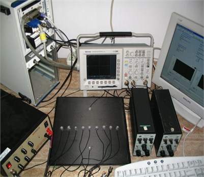
The overall test configuration in this study is shown in Fig. 1(a). The test set-up consists of a NI PXI-based data acquisition (DAQ) system incorporated with a NI PXI-8176 embedded controller, a NI PXI-5411 arbitrary function generator and NI LabVIEW software, a Krohn-Hite Model 7602 Power Amplifier, a composite plate with a surface-mounted PZT sensor network, two Brüel & Kjær Type 2635 Charge Amplifiers and a Tektronix TDS3012 Digital Oscilloscope.
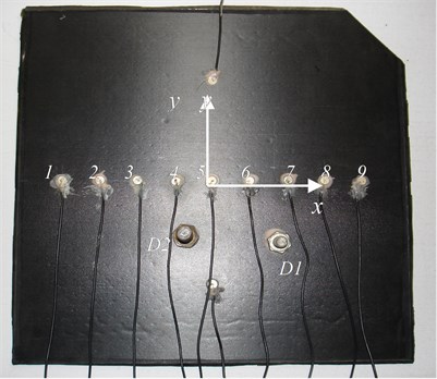
Fig. 1(b) shows the composite plate with PZT network. A [03/–45/45/03/–45/452/3]S graphite fiber & epoxy phenolic resin T300/648 symmetric laminate is selected for illustration. Fiber Volume Fraction is 65 %. The plate dimension is 300 mm×300 mm×2.1 mm and the material properties for a single lamina are listed as follows: 125.44 Gpa, 7.947 Gpa, 4.748 Gpa, 4.092 Gpa, 0.33, 1587.9 kg/m3. The subscript 1, 2, and 3 refer to principal material axes along fibre, transverse, and thickness direction respectively. The sensor network contains 11 PZT sensors (diameter: 8 mm, thickness: 1 mm), denoted by 1, 2, …, 11. The 1~9 PZT sensors are located along the -axis from [–120, 0] mm to [120, 0] mm with spacing 30 mm. Nine of the sensors also act as actuators. Each actuator gives one shot to excite the transient diagnostic wave in the composite laminate. The traces, which are collected by all of the remaining sensors, assemble the time section data record to reconstruct the response wave field. The wave field solely reflected from the damages can be obtained by subtracting the wave field without damage from that with damage. Two steel nuts, marked with D1 & D2, are used to mount on the surface of the test composite laminate by high strength glue to simulate delaminations respectively: D1’s centre is at the point [49, –52] mm, diameter is 16 mm; D2’s centre is [–24, –45] mm, diameter is 20 mm.
Fig. 1a) An experimental built-in damage detection and identification system, b) a T300/648 symmetric laminate for NDT
a)
b)
3. Wave propagating in laminate
3.1. Dispersion relationships
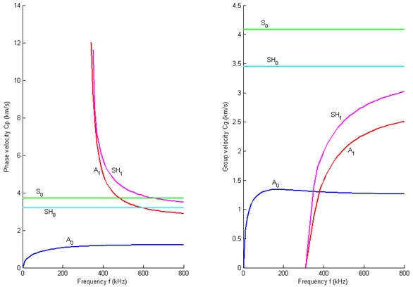
Lih and Mal [7, 8] have shown that the approximate solution from MPT gives accurate results for the lowest mode of flexural waves. In this study, Mindlin Plate Theory (MPT), which takes into account the effects of transverse shear deformation and rotary inertia, is used to model the flexural waves propagating in a thin composite plate, and the dispersion relationships shown in Fig. 2 and 3 could be calculated according to the reference [6]. Fig. 2 shows the dispersion curves of different wave modes propagating in the composite laminate along 0° direction calculated by this approximate plate theory MPT. It is noticed that the beginning portions of the S0, SH0 and A0 mode are relatively flat in the low frequency range, thus the dispersive effect in this range is insignificant. This is a desired feature for a practical SHM using lamb wave as diagnostic signals. Although the S0 mode of extensional wave is ideal for SHM since it has almost non-dispersive effect in the low frequency range, it was difficult to work with such mode in practice because this mode signal is very weak and attenuates quickly [9]. The SH0 wave is not applicable either. In addition, in the low frequency range, A1 and SH1 indicate terribly dispersive effect. Fig. 3 shows the dispersion curves of different modes in the composite laminate along 90° direction. The same phenomena of these wave modes could be observed. Thus it’s suitable to choose the A0 mode wave as the diagnostic signal. The dispersion relationships and the group velocities of A0 wave will be validated by experiments at Section 5.1.
Fig. 2Dispersion curves of the direction 00: (L) Phase velocity; (R) Group velocity
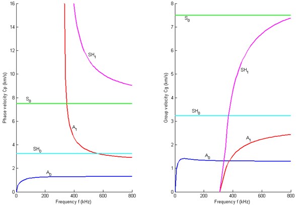
Fig. 3Dispersion curves of the direction 900: (L) Phase velocity; (R) Group velocity
3.2. Governing equations
In order to simplify the governing equation of motion for the A0 flexural waves, two new vectors and are defined. Then the governing Equation (1) can be expressed as a first-order equation in a matrix form [3]:
3.3. Finite difference algorithm
A 2-6-order finite difference algorithm (second-order accuracy in time and sixth-order accuracy in space) is employed in this study to simulate the A0 flexural waves propagating in a composite plate [6]. Consider the major portion of Equation (1):
The MacCormack splitting method can be expressed as the following compact form:
where is the output value of the time step and is for the time step. , , and are the backward-forward operators and forward-backward operators in the , directions respectively. Each operator processes the calculation by a half time step; thus a complete update of Equation (3) includes four operators in two time steps. In each sequential time step, the order of the , direction updates is reversed, so is the order of forward-backward and back-forward operators.
For the term in Equation (1), the increment of due to is calculated in advance by using and then at each time step this term is added into each grid point. This method avoids the difference computation at each time step thus speeds up the calculation.
4. Imaging damages by pre-stack migration
For a distributed linear array actuator/sensor system, each actuator excites the lowest mode of transient flexural incident waves A0 with the same waveform into the structures. All sensors collect the back-scattered waves, and sensor data are assembled through a time section.
4.1. Excitation-time imaging condition
The excitation-time imaging condition developed by Chang and McMechan [10] is employed in this study. The imaging condition is based on a concept that if both the incident wave and the reflected wave are extrapolated, the damages exist at the places where these two waves are in phase to each other. According to this condition, a grid point is imaged at its excitation-time when this point is excited at this time by the incident energy travelled from the actuator. This imaging condition is explicit, and each point in the image space has its own image time. Therefore, at each reverse time step , imaging is processed on the entire grid points and those points located on a locus are defined by:
where is the direct (physical) time arrival from the actuator to the points, is the maximum time step index, and is the time step of the finite difference algorithm.
The imaging condition locus can be determined based on ray tracing theory. When the actuator excites the incident waves, the wave energy propagates at the speed of the group velocity along a ray path. For the flexural waves in a composite plate, besides the composite material properties, the group velocity also depends on the propagation direction and the wave frequency . Therefore, for a given direct time arrival , the locus can be formed by:
where is the distance from the actuator to the locus and is the magnitude of group velocity of the flexural wave mode [6].
The imaging condition locus for each extrapolation time step can be computed prior to the reverse-time migration and is used as a reference table in the upcoming migration process.
4.2. Reverse-time extrapolation of reflected wave field and application of imaging condition
The finite difference algorithm is used for reverse-time migration. The time section is now reversed with respect to time. Reverse-time extrapolation is a boundary-value problem of the transverse deformation velocity in which the finite difference mesh is driven with the time reverse of the trace received at each sensor. At each finite difference time step, new boundary values are extracted along a constant time slice through the sensor data and inserted at the corresponding sensor locations. In practical applications, the time step for migration is equal to the sampling interval of the A/D device. As time moves backwards, the reflected energy originating from the damages will focus back to the boundary of the damages, pass through and then defocus (see reference [6] for details of this procedure).
At each extrapolation step of applying the imaging condition, the points on which the imaging condition locus crosses with the back-propagating wave front are imaged in terms of the velocity of the transverse deformation .
4.3. Stacking the images
When time back-propagates to zero, the reverse-time migration process is completed and the reflected energy may be imaged at the damage boundaries. Basically, the fidelity of the resulting image depends on the wave energy received by the sensor array. In other words, some portions of the damage cannot be imaged unless the incident wave reaches this damage site and the reflected waves are collected by the sensor array. Due to the finite area of the damage and the existence of the multiple damages, only a single reverse-time migration from one actuator is not sufficient to image all areas of the damages. Accordingly, exciting the waves from different actuators and producing the images of multiple damages is needed. Then, images from all the actuators are stacked or superimposed; in this case, the signal-to-noise ratio of final image resolution of the multiple damages can be enhanced. Since the reverse-time migration procedure is done prior to stacking images, this processing technique is called pre-stack migration.
5. Experiment
5.1. Validation of dispersion relationships
The excitation of transient waves from an actuator is a Hanning window modulated sinusoid transverse loading which driven by voltage signal governed by:
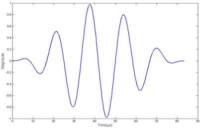
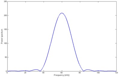
where is the Heaviside step function, is the amplitude of the excitation signal, is the number of peaks of the loading, and is the central frequency. The advantage of this loading is that it has compact support in time domain (see Fig. 4(a)) and its frequency components concentrate at in frequency domain (see Fig. 4(b)), thus the excited wave is relatively non-dispersive.
Fig. 4a) The excitation signal in time domain; b) the excitation signal in frequency domain
a)
b)
Fig. 5 shows the group velocity and phase velocity curves of A0 mode wave along 90° direction calculated by MPT compared with experimental results. Both solutions match well in the low frequency range. Therefore, wave behaviour in the portion of A0 mode, prior to the cut-off frequency, can be conveniently modelled and used for the real SHMS. Here we choose the flexural wave mode A0 as diagnostic signal for migration. In this study, 5, 40 Volts and are chosen to ensure only the lowest mode of flexural waves propagating in the composite.
Fig. 5Group velocity of A0 mode wave along the direction 90°
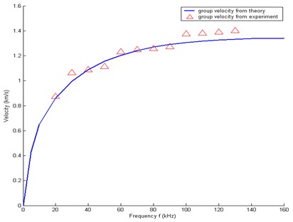
Fig. 6Group velocity of A0 mode wave at 60 kHz
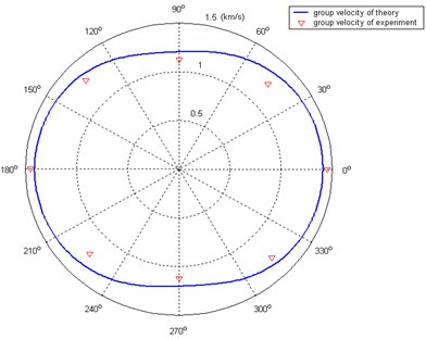
Fig. 6 illustrates the velocity distributions of A0 mode wave propagating in the test laminate. The velocities strongly depend on the direction of propagation due to the material anisotropy and layup. Experimental solution shows that it correlates well with theoretical result. Thus, it could provide the base information for constructing the excitation-time imaging condition.
5.2. Result of pre-stack migration
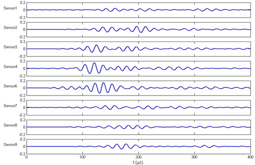
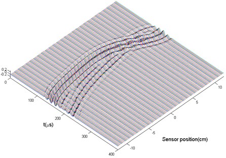
Fig. 7(a) is the experimental sensor data scattered from the two damages actuated by PZT 5 at [0, 0] mm. A corresponding reflection field could be interpolated by this time section. Because of the anisotropy of material, to accurately describe the time section by interpolation method still needs further researches. For convenience, fifth polynomial curve fitting through solving the least-squares problem was temporarily applied here for interpolation. Fig. 7(b) is the reconstructed reflection field actuated by PZT 5.
Fig. 7a) The time section actuated by PZT 5; b) the reconstructed wave field actuated by PZT 5
a)
b)
The plate is discretized by a 240×240 finite difference mesh ( 1.25 mm) when doing the migration procedure with the finite difference algorithm. The time interval is chosen as 0.04 μs.
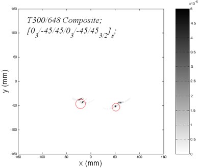
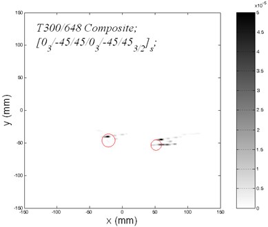
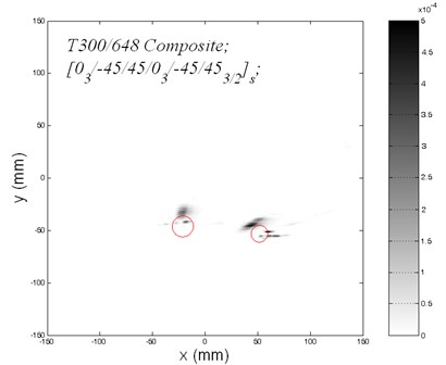
The plate is imaged by extracting the velocity of the transverse deformation at each grid point and is displayed in a plot with Gray colormap. Two images of the multiple damages generated by using reverse-time migration are shown in Fig. 8(a) and Fig. 8(b). Two circles indicate the boundaries of the target damages. Fig.8a is the image migrated from a single shot generated by PZT 4 located at origin [–30, 0] mm. Fig.8b displays the reverse-time migration image with PZT 7 located at [60, 0] mm. Both of the two image show that the reverse-time migration successfully propagates the reflected energy back to the secondary sources, and imaging areas are nearly located at the boundaries of the target damages. However, migration of the reconstructed wave field from a single actuator did not give a complete image of the multiple damages. The reason is that the incident waves from different actuators reach the different boundary portions of damages.
Figure 9 gives the final stacking image from the reverse-time migration images of nine actuators. All of the imaging areas are located mainly on the boundaries of the target damages. Thus, the pre-stack reverse-time migration method is suitable for imaging multiple damages in the composite laminate plate. However, the results have some diversity from the real targets. This might be because of errors origining from the interpolation method for reconstruction scattered wave fields. Besides, because the sensor array is placed above the damages, only the reflected energy from the upper portions of the damages can be collected and migrated to the secondary sources. Thus the lower portions of the damages cannot be imaged.
Fig. 8a) Image of two circular damages by using reverse-time migration from actuator 4; b) Image of two circular damages by using reverse-time migration from actuator 7
a)
b)
Fig. 9Stacked image of two circular damages from nine actuators
6. Conclusion
This experimental study demonstrates the ultrasonic Lamb wave-based pre-stack reverse-time migration as an advanced technique that can be used in an active SHM system. Through this experimental study, it shows that the migration can effectively interpret the sensor data recorded by a distributed linear array sensor system and make it possible to establish an active, in-service and intelligent monitoring system.
However, several limitations of the current approach should be paid attention to. First, it is valid for thin composite laminates and the frequencies being relatively low because the wave model is based on approximate plate theory. Second, due to the two-dimensional finite difference algorithm, the computational time cost is relatively very high. In addition, an advanced interpolation algorithm needs to be developed such that the sensor spacing could be much larger than the spacing of finite difference mesh, thus the time section could be constructed using a smaller number of sensors. Lastly, a linear array of actuators/sensors network distribution should be optimised to image the entire area of the target damages.
References
-
Boller C. Next generation structural health monitoring and its integration into aircraft design. International Journal of Systems Science, Vol. 31, Issue 11, 2000, p. 1333-1349.
-
Liu P. L., Tsai C. D., Wu T. T. Imaging of surface-breaking concrete cracks using transient elastic wave. NDT&E International, Vol. 29, Issue 5, 1996, p. 323-331.
-
Lin X., Yuan F. G. Damage detection of a plate using migration technique. Journal of Intelligent Material Systems and Structures, Vol. 12, Issue 7, 2001, p. 469-482.
-
Lin X., Yuan F. G. Detection of multiple damages by prestack reverse-time migration. AIAA Journal, Vol. 39, Issue 11, 2001, p. 2206-2215.
-
Lin X., Yuan F. G. Experimental Study of applying migration technique in structural health monitoring. Structural Health Monitoring: the demands and Challenges, CRC Press, 2001, p. 1311-1320.
-
Wang L., Yuan F. G. Damage identification in a composite plate using prestack reverse-time migration technique. Structural Health Monitoring, Vol. 4, Issue 3, 2005, p. 195-211.
-
Lih S. S., Mal A. K. On the accuracy of approximate plate theories for wave field calculations in composite laminates. Wave Motion, Vol. 21, Issue 1, 1995, p. 17-34.
-
Lih S. S., Mal A. K. Response of multilayered composite laminates to dynamic surface loads. Composite Part B, Vol. 27B, Issue 6, p. 633-641.
-
Sohn H., Park G., Wait J. R., Limback N. P., Farrar C. R. Wavelet-based active sensing for delamination detection in composite structures. Smart Materials and Structures, Vol. 13, Issue 1, 2004, p. 153-160.
-
Chang W. F., McMechan G. A. Reverse-time migration of offset vertical seismic profiling data using the excitation-time imaging condition. Geophysics, Vol. 51, Issue 1, 1986, p. 67-84.
About this article
This research is supported by State Key Laboratory of Mechanics and Control of Mechanical Structures (Nanjing University of Aeronautics and astronautics) (Grant No. MCMS-0513G02).
