Abstract
The main aim of the research is to determine (by experiment) the dynamic characteristics of angle comparator carriage on which optical system is attached on it and to compare the experiment with the results obtained by theoretical calculations.
1. Introduction
Remote sensing technology is recently increasingly used. Modern remote sensing technology requires the accuracy of measurement and calibration [1]. For accurate calibration of the remote sensing images the angles of optical axes should be perfectly measured [1-6]. The lot of work was done to solve the problems of precision mechatronical systems designed for angle measurement [2-11]. Interferometers [1-5] and autocollimators [6-8] were mostly used for optical measurement of small angles.
A precision angle measurement comparator is an integrated mechatronic system. Designing of such systems according to conventional methodology based on strength criteria frequently does not ensure protection against effects caused by small (in micrometers or nanometres) undesirable influence of vibrations on beam focus point. These hard-to-predict vibrations may be caused by seismic excitation of the construction, although often the reason may be functioning peculiarities and design of the machine [12-13]. For example, small vibrations can be caused by operation of motors and gears which are transmitted to construction depending on its geometrical shape and dimensions what determines its stiffness and mass distribution. Construction and stiffness of guidelines, damping in loose connections, etc. are very important. Even small temperature changes may influence on looseness of guidelines and connections or to cause thermal deformations that eventually influence on position of the point illuminated by the laser beam [14-15]. These deformations and displacements are transient doing impossible to eliminate their effect by standard means of compensation.
At designing of precision systems the underlying principles ensuring maximum stiffness of the construction are applied or at least pursued. “Open” shell structures and structural elements loaded by bending strains should be avoided. However, this is not always easy because inevitably the compromise have to be searched, balancing functionality of the machine, stiffness of structural elements and the overall stiffness, dimensions, cost, etc.
2. Measurement equipment and object of research
The research object is a precision system of angle calibration (an angle measurement comparator). This device has multiple applications: measurement of angular scales (limbs) and angular transducers. The angle measurement comparator consists of the following components:
• Precision turn system comprising a precision spindle and gear;
• Vibration-proof base;
• Reference angle system;
• Mechanical assembly ensuring functionality of the comparator;
• Calculation-control unit;
• Measurement system of positioning of limb marks.
Basic mechatronical system is used for calibration of limbs and angular transducers. The system is based on a massive plate of fine-grained granite with stably attached aerostatic spindle in a bearing ring. The spindle is rotated trough a worm-gear. The worm-gear in an axial direction is supported by aerostatic bearings while in radial direction is supported by the roll bearings. Bearings of both types are installed in subassemblies of their positioning. Radial and axial forces acting on bearings are decreased by connection the spindle and worm wheel by elastic elements. It produces the pure driving torque which from a motor to spindle is transmitted via the worm wheel and reducer. Alternatively, the spindle can be rotated manually, the reducer then is disconnected.
To avoid reverse errors and negative hysteresis influence on accuracy the limb of angle measurement system is rigidly connected to the spindle without intermediary mechanical sliding elements.
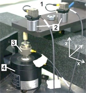
The following measurement equipment was used for modal analysis of an exploratory system (Fig. 1): 1. Triaxial accelerometer 4506; 2. Magnets of accelerometer attachment; 3. Force sensor 8201; 4. Vibrator 4811.
Fig. 1Equipment used for modal analysis
3. Modelling of mechanical system of angle comparator
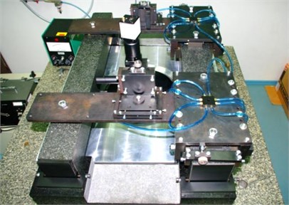
The most appropriate method to improve construction of the comparator is to change the carriage construction. Accordingly, the carriage system has been analyzed (Fig. 2). A dynamic model of the carriage has been also developed. Granite base subsystem is being dismissed. Missing connections are replaced with experimentally measured external excitations , , , , , of the base, attached at appropriate coordinates.
Generalized Lagrangian coordinates that specify position of the carriage of comparator during vibrations have been selected. Primarily, a coordinate system , , , connected to the carriage of an angle measurement comparator and moving together with this carriage during vibrations has been accepted. The system starting point was selected thus that it coincides with the stiffness centre of a carriage of an angle measurement. After that the other motionless coordinate system , , , was got matching the previous one , , , when the carriage of the angle measurement comparator is at idle state and swayed only by the weight force (systems , , , and , , , showed in Fig. 3, are in such position). Suppose that the starting point of the system , , , during vibration of the carriage of the comparator at time moment differs from the point and its position is defined by coordinates , , in the motionless coordinate system , , , . Furthermore, it is assumed that the carriage of an angle measurement comparator rotates to small angles , , around coordinate axes , , .
Fig. 2General view of carriage of angle measurement comparator
The position of the comparator carriage during vibrations would be defined by six generalized Lagrangian coordinates , , , , , .
It is a general case of a dynamic model of the comparator carriage when it can be considered as a solid body. For simplifying the model it is considered that supports of the carriage deform only in a vertical position. Then small displacements of the carriage during vibrations would be defined by three generalized coordinates , , (translational vibrations along coordinates and and torsional vibrations are ignored). Since turns and of the carriage are under assessment, their moments of inertia and around axes , as well as mixed moment of inertia to these axes must be known. It is considered that the position of the carriage mass centre of the comparator and moments of inertia during operation consist of time constant and of time-varying parts over time (mass is constant):
All these values are considered to be known (when vibrations of the carriage are analysed assessing vibrations of granite guides only then values of and would be equal 0, because coordinates of mass centre and coincide with coordinates and of coordinate system , , , ).
To facilitate the further derivation the external excitation force produced via aerostatic supports of carriages is transferred to the beginning of the coordinate system , , , . Moments of rotational force and resulting from the transfer are also added. Displacements of the carriage of angle measurement comparator under the generalized coordinates , and are ignored. The force acting in the direction of axis as well as moments of forces and remain:
where is stiffness coefficient, and are displacements from centres and to supports; , and are displacements of granite guides at points , and .
Fig. 3Dynamic model of mechanical system of carriage of angle measurement comparator
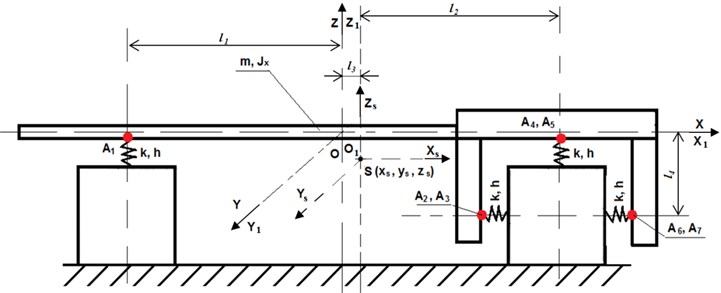
a) Front view
b) Top view
Kinetic energy is expressed as:
Potential energy can be initially expressed as:
where is constant stiffness coefficient of vertical elastic displacement of support (the same for all supports); is elastic displacement of attachment of th support to the machine location in vertical direction (1, 4, 5).
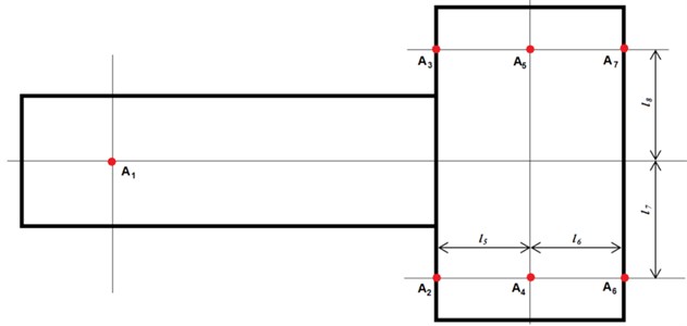
Displacements expressed by generalized coordinates , and (Fig. 4) are:
By inserting the values into Eq. (9) we will obtain the final expression of the potential energy:
Expression of dissipative function for the case of analysis would be analogous to expression of potential energy after replacement of stiffness coefficient by resistance coefficient and of coordinates , , by their derivatives , , over time :
Generalized forces would be:
The derivatives of equations are:
where:
Obviously:
because the generalized coordinates , , are not included into the kinetic energy, (but only derivatives of these coordinates), in this case:
Accordingly:
The values of derivatives and generalized forces are inserted into Lagrange equations of the second order, so such differential equations of machine vibrations are obtained:
The markings are: , , , , , . Here is a differentiation operator. After such transformation the following form of Eq. (20) is obtained:
Then:
where:
As it has been mentioned, values , , and their derivatives over time are known time functions and operator is not applied to them. It is only applied to derivatives of variables , , over time .
Inserting markings (when 3):
Now instead of Eq. (21) the following system of equations is received:
The system of equations is solved by corresponding coordinates , , :
4. Results of modelling
Table 1 shows values of parameters of the model.
Table 1Values of parameters of the model
Parameter | Mass , kg | Inertia moment , kgm2 | Inertia moment , kgm2 | Inertia moment , kgm2 | Distance , m | Distance , m | Stiffness coefficient , N/m | Damping coefficient , Ns/m |
Numerical value | 25 | 20 | 15 | 6 | 0.15 | 0.25 | 32000 | 8.0-e7 |
Table 2 shows values of parameters of jump excitation signals.
Typical amplitude-frequency and phase-frequency characteristics (Bode plots) of the system are shown in Fig. 4 where Bode plots obtained with LTI-object watcher are presented.
Table 2Parameters of jump excitation signals
Coordinate | MATLAB marker | Jump time, s | Load |
z | 0 | 1 N | |
Phix | 0,5 | 1 Nm |
Fig. 4Amplitude-frequency characteristics of the system
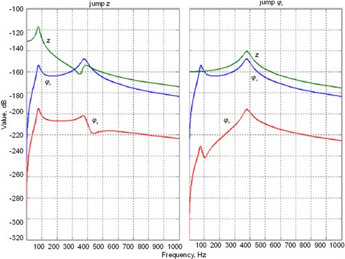
The obtained results of modelling indicate that resonance frequencies of the system are 75, 81 and 375 Hz.
Directions of seismic excitation generally matches direction and in case of symmetrical effect on all aerostatic supports and all of them being of equal stiffness it will cause vibrations of the carriage in the direction , which is less important to operation of angle measurement comparator. When excitations affecting aerostatic supports at one end of carriage of angle measurement comparator differ from excitations affecting aerostatic supports at the other end it is worse. This will result torsional vibrations around coordinate which will have components along axis. These frequencies may fall into the first resonance zone. Amplitude-frequency response to this excitation has been calculated (Fig. 4) accepted its amplitudes close to the experimentally measured amplitudes which makes the result close to the actual one.
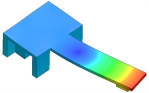
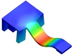
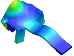
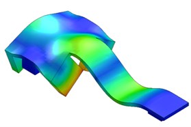
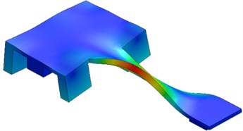
In order to simulate a more accurate response of the carriage of angle measurement comparator and determine the possible resonant frequencies a finite element method (FEM) analysis has been performed in SolidWorks software package environment. Fig. 5 shows the first five modes.
Directions of seismic excitation generally match the direction z and in the case of symmetrical action on all aerostatic supports and if all of supports are of equal stiffness, the carriage will vibrate in one direction . Its importance to operation of the comparator is smaller. If excitations at one end of aerostatic supports are different from these at the other end, the effect is worse, because it results in torsional vibrations around the coordinate . These excitation frequencies may fall into the first resonance zone.
In order to simulate the more accurate response of the carriage to excitation and determine the possible resonant frequencies the finite element method (FEM) analysis was performed in SolidWorks software package environment. Fig. 5 shows the first five modes of vibrations.
Fig. 5Results of modal analysis
a)
b)
c)
d)
e)
5. Vibrations of angle comparator carriage
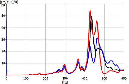
The experimental results of response of mechanical system of the comparator carriage to external excitation in vertical direction are shown in Fig. 6.
Measurement results (Fig. 6) show that the dominant frequencies are 269, 294-296, 365, 427-437 and 462 Hz. The results indicate that the major dominant amplitudes are at 294-296, 427-437 and 462 Hz.
Results of experimental measurements show that dominant amplitudes obtained above the 250 Hz.
Fig. 6Frequency spectrum of experimental modal analysis (red and blue – respectively x and y axes; black – z axis, axes are showed in Fig. 1)
The vibrations of angle comparator carriage influence accuracy of angle measurement. Because the CCD camera is attached to the angle comparator carriage, the angle measurement error is directly proportional to CCD camera vibrations.
Vibrations of the carriage in direction of axis defocus the optical detection system intended for measurement of limb dashes position. This reduces the calibration accuracy. Error depends on the parameters of the optical system and the size of vibration displacement.
Linear displacements and deformations of the carriage displace the detection system in measurement (calibration) plane with regard to limb. This has a direct influence on errors of the determined position.
Angular displacements and deformations of the carriage change the angular position of the optical system in regard to limb. This has the same influence as previously mentioned linear displacements and deformations.
The size of calibration of angular errors depends on the parameters of the optical system and previously discussed linear and angular displacements and deformations of the carriage of angle measurement comparator.
6. Conclusions
It has been determined two modes up to 100 Hz (75 and 81 Hz) in theoretical researches (when simulated as a rigid body).
Experimental modal analysis on angle comparator carriage has been performed in order to determine first five modes: 269, 294-296, 365, 427-437 and 462 Hz.
Modal analysis shows the linear and angular deformations of basic details. According to this relative displacements between the measurement system and optical detection system, which cause calibration errors, may be assessed. Modal analysis also supposes construction weaknesses and reduction of deformations, which cause calibration errors.
References
-
Ruimin Liua, Xiqing Guoa, Jin Yua, Yingying Qinab, Qiang Biana, Weiyan Lia A novel instrument for high precision angle measurement of optical axes. Optik, Vol. 124, 2013, p. 1132-1135.
-
Hussain G., IkramM. Optical measurements of angle and axis of rotation. Optics Letters, Vol. 33, 2008, p. 2419-2421.
-
Huang P. S., NiJ. Angle measurement based on the internal-reflection effect and the use of right-angle prisms. Applied Optics, Vol. 34, 1995, p. 4976-4981.
-
Zhou W., Cai L. Interferometer for small-angle measurement based on total internal reflection. Applied Optics, Vol. 37, 1998, p. 5957-5963.
-
Zhong J., Qi P., Chen C., Chen Z. High-precision small-angle measurement based on laser self-mixing interference. Frontiers in Optics, Laser Science XXVI, Optical Society of America, 2010.
-
Bournachev M. N., Filatov Yu. V., Kirianov K. E., Loukianov D. P., Mezentsev A. F., Pavlov P. A. Precision angle measurement in a diffractional spectrometer by means of a ring laser. Measurement Science and Technology, Vol. 9, 1998, p. 1067-1071.
-
Just A., Krause M., Probst R., Wittekopf R. Calibration of high-resolution electronic autocollimators against an angle comparator. Metrologia, Vol. 40, 2003, p. 288-294.
-
Brucas D., Giniotis V. Creation of a multi-reference-angle comparator. Optical Engineering, Vol. 48, 2009, p. 033602.
-
Brucas D., Giniotis V. Calibration of precision polygon/autocollimator measurement system. Journal of Physics, Conference Series, Vol. 238, 2010, p. 012014.
-
Kir’yanov V. P., Kir’yanov A. V. Analysis of modern technologies for synthesizing goniometric structures for high-accuracy angle measurements. Journal of Optical Technology, Vol. 74, 2007, p. 823-830.
-
Zhaoxin S., Xiaohui C. A technology to get coordinate-system of cube-prism in electron-theodolite surveying system. Journal of Astronautic Metrology and Measurement, Vol. 26, Issue 4, 2006, p. 73-75.
-
Kasparaitis A., Vekteris V., Kilikevičius A. Investigation of vibrations acting on mechatronical comparator. Ultrasound, Vol. 62, Issue 1, 2007, p. 38-41.
-
Kasparaitis A., Vekteris V., Kilikevičius A. Line scale comparator carriage vibrations during dynamic calibration. Journal of Vibroengineering, Vol. 10, Issue 3, 2008, p. 347-354.
-
Kilikevičius A., Vekteris V., Slivinskas K., Kasparaitis A. Investigation of dynamics of the mechatronical comparator. Ultrasound, Vol. 64, Issue 2, 2009, p. 17-23.
-
Kilikevičius A., Vekteris V., Slivinskas K., Kasparaitis A., Juraitis S. Research of the influence of vibrations to the line scale gage calibration quality. Solid State Phenomena, 2010, p. 47-55.
About this article
