Abstract
Nowadays, due to the development of information industry and technologies, the objective of cellular phone is not only to communicate, but also to give people various functions such as e-banking, web surfing and even excitement and fun. Because of increased usage of the cellular phone, the available time of the phone rechargeable battery is getting shorter. Therefore, in order to extend the serviceable time of the rechargeable battery, we propose self-generation system using a tubular type of permanent magnet linear self-generator (TPMLG) which can be embedded in cellular phone. The vibrational model is studied utilizing the mechanical resonance and the magnetic circuit such as permanent magnet, steel yoke and coil is designed to improve electricity generation. To investigate the electric characteristics of designed generation system, the transient finite element analysis using commercial software “MAXWELL” is performed.
1. Introduction
A cellular phone is most commonly used mobile device by means of information transfer among the people who are far away to keep in contact. The developments of science technology and information industry have given cellular phone many features. As cellular phone is used for various purposes such as calling, messenger, e-banking, game, web surfing, etc. the high battery capacity is required. Despite battery capacity is improved much more than a few years ago, the dramatically increased usage of the cellular phone makes the battery serviceable time shorter and shorter. Occasionally, cellular phone users may not use their phones for personal urgent calling which is the original function of cellular phone such as communication with others due to battery discharge [1].
In order to solve its inconvenience, the small and medium-sized self-generation systems for battery self-charging in emergency have been developed among academies [2, 3]. It should be noted that several new applications for power harvesting were studied and developed using a small linear electric generator at low excitation frequencies which represent the general human activities such as walking and shaking motion [4]. Also, many research about human activities for power harvesting was conducted to characterize human motion [5, 6]. Most of these generation system convert the energy from human activity to electric energy and one of them has been commercialized. However, it is larger than cellular phone and not embedded in the cellular phone [7]. Accordingly, it must be carried in the bag separately which results in considerable inconvenience. Finally, it has not been sold much.
In this research, the internal generation system for self-recharging the battery of cellular phone is introduced. That is, it is designed to be embedded in the cellular phone. It can charge the battery in both modes which are walking mode and shaking model. In waking mode when the users carry their cellular phone in pocket or bag, the mechanical energy by walking motion can be converted to electric energy which charge the battery continuously and extend the battery serviceable time. In case of emergency such as full-discharge of the battery, the shaking of cellular phone by the hand motion of user generates the electricity quickly which enables them to use urgent call.
To maximize the mechanical energy from the user’s motion, the resonance phenomena needs to be driven by matching the mechanical natural frequency of generation system and the frequency of user’s motion such as waling or shaking [8, 9]. Therefore, the vibrational modeling is constructed to investigate the vibration characteristics [10, 11]. In addition, the tubular type permanent magnet linear generator TPMLG is designed for effective electric generation [12].
The finite element analysis (FEA) using commercial software “MAXWELL” is performed to simulate the electric generation. Finally, the prototype of proposed generation system is manufactured and its experiment is performed. The results of the simulation and experiment show my generation system has enough possibility to be in practical use.
2. Geneation system
2.1. The structure and principal of the TPMLG
Fig. 1 shows the schematic diagram of TPMLG which consists of two main parts such as slider and stator. The slider includes a combination of a steel bar called pole-shoe and a permanent magnet. The permanent magnets are axially magnetized with the poles face to face and are mounted alternatively between the pole-shoes. The pole shoes are made of steel 1010 and serves as conductors of the magnetic flux. The stator consists of electromagnetic coil and coil-housing which is soft-magnetic. Also, coil winding is formed with several 2-pole 3-phase [13]. Remains of device are two springs, linear ball-bush on the ends of the slider and casing for the overall parts. Two springs enables the slider to vibrate elastically for resonance and the ball bush guides the slider in linear motion.
Fig. 1Schematic diagram of the proposed linear generator
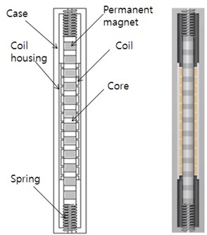
Fig. 2Diagram of the energy conversion
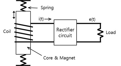
Fig. 2 shows the diagram of the energy conversion principle. The electro motive force [EMF] is generated at the stator coils terminals as the slider vibrates up and down by the heaving motion of cellular phone which is caused by the mechanical energy such as shaking motion and walking motion of users. The EMF is calculated by Faraday’s law and can be expressed by the following Eq. (1):
where is the number of turns per coil, is the flux passing in each turn in real time , is the slider speed, and is the distance along -direction. So, the electromotive force is proportional to the number of coil turns, the variation of magnetic flux which interlinks the coil winding respect to the displacement of slider, and the speed of the slider [14].
2.2. Vibration characteristic analysis of the linear electric generator
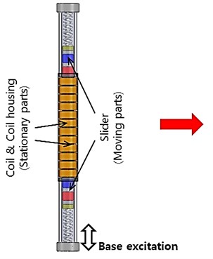
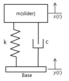
To maximize the mechanical energy from the user’s motion, the resonance phenomena needs to be driven by matching the mechanical natural frequency of generation system and the frequency of user’s motion such as waling or shaking. The vibrational model including slider, two springs and the base exciter is constructed in Fig. 3. The excitation by user’s motion is supposed by the base excitation. It can be expressed mathematically in equation (2). The displacement of the base and slider is denoted and respectively.
Fig. 3Simplified schematic diagram of the proposed linear generator
a)
b)
where is expressed as if the walking and shaking motion are supposed to be sinusoidal. So, amplitude of is calculated as below equation (3).
The frequency of walking motion is in the range of 2 Hz to 2.2 Hz [6] and the frequency of shaking motion is in the range of 3.0 Hz to 5 Hz.
where – natural frequency, – base excitation frequency.
In case of the walking motion, the displacement amplitude of base excitation is approximately less than 2 cm which does not create enough displacement of slider for electric generation. Therefore, mechanical resonance is required to extend the speed of slider. In case of shaking motion, the 5~6 cm displacement amplitude of base excitation is always enough to create the displacement of the slider for electricity generation.
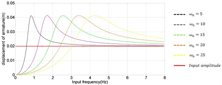
Fig. 4 shows the displacement amplitude of base excitation and slider according to the varying from equation (3). According to the Fig. 4, vibrational characteristic is modified by changes of natural frequency. In case of , we can find that displacement amplitude of slider is amplified at walking motion. Therefore, we can determine optimal natural frequency and spring stiffness for enough vertical motion.
Fig. 4Amplitude of base and slider according to the varying ωn
2.3. Design of magnetic circuit
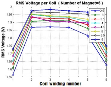
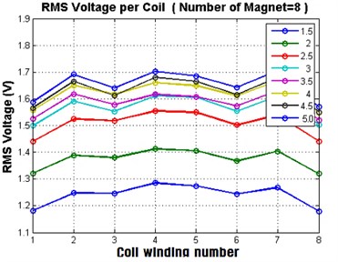
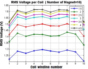
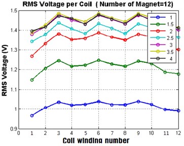
In order for the proposed device to be installed inside of cellular phone, the whole size of generation system is less than 100 mm in length and 8 mm in diameter. Accordingly, the magnetic circuit such as permanent magnet (PM), pole-shoe, and electromagnetic coil is designed to satisfy the size specification with large electricity generation. Here, the number of PM and height ratio of PM and pole-shoe need to be determined. The number of coil winding is designed as same as one of PM. Finite element analysis using commercial software “MAXWELL” is performed. Fig. 5 shows the induced RMS voltage in each coil winding at no load is calculated varying the height ratio of PM and pole-shoe. Fig. 3(a), (b), (c) and (d) shows the results in 6 PMs, 8 PMs, 10 PMs, and 12 PMs respectively. In Fig. 5, the legend represents the height of PM.
Fig. 5The induced RMS voltage in each coil winding at no load
a)
b)
c)
d)
In case of 6 PMs with 6 coil windings, the largest voltage is induced in each coil winding, but the total voltage which adds up the each winding is the largest in case 12 PMs with 12 coil windings. In Fig. 5(d), we can find that the height of PM 3.5 mm (height ratio between PM and pole-shoe is 1:0.5) can produce the largest output voltage. Therefore, the design with 12 PMs and 12 coil windings and height of PM 3.5 mm are selected for prototype.
2.4. Load-analysis
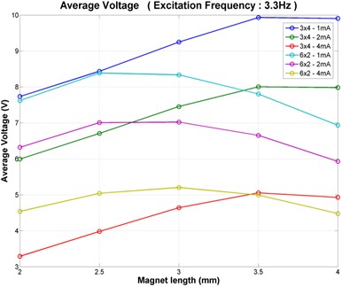
The external circuit is designed for load-analysis as shown in Fig. 6. The circuit consists of rectifier, capacitance and external load. The rectifier converts the AC signal to DC signal. In addition, a capacitor is used to store this positive charge and smooth out the lumpy signal. Table 1 shows the specification of external circuit. The quantity of capacitance is approximately 300 µF since the frequency of the wave is on the order of a few hertz. Fig. 7 shows the results of load analysis which shows the induced voltage under varying current-load (input frequency 3.3 Hz and 2.2 Hz).
Fig. 6Diagram of the external circuit
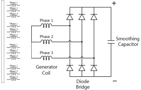
Table 1Specification of external circuit
Value | |
Capacitance | 300 µF |
Number of coil turns | 860 turns |
Coil resistance | 140 Ω |
Constant current load | 1, 2, 4 mA |
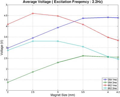
Fig. 7The results of the load analysis per current-load (a) input frequency 3.3 Hz, (b) input frequency 2.2 Hz
a)
b)
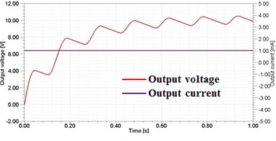
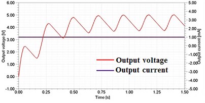
Fig. 8 shows the output voltage and current versus time at input frequency. Fig. 8(a) shows the results of output voltage in shake mode which has input frequency of 3.3 Hz whereas Fig. 8(b) shows the results of output voltage in walking mode which has input frequency of 2.2 Hz. In both modes, the output voltage is over 3.7 volts which is minimum required voltage for recharge of lithium battery used in cellular phone.
Fig. 8Output voltage and current (a) input frequency 3.3 Hz (shaking motion) (b) input frequency 2.2 Hz (walking motion)
a)
b)
3. Experiments
To confirm the simulation results, a prototype of the linear generation system was manufactured and experimental apparatus were set up. Unlike simulation model, the coil housing of the prototype is crafted out of acrylic material which is nonmagnetic material because the assembly is too difficult to be performed due to the attractive between PM and soft-magnetic coil housing.
Fig. 9 and Fig. 10 show a prototype of the linear generation system and experimental apparatus for the experiment respectively. Fig. 11 shows the experiments flow diagram. Table 2 shows the experimental condition according to the input frequency and external load.
A hydraulic actuator shakes the manufactured generator to depict smart phone user’s shaking motion and walking motion according to Table 2. As the slider of generator vibrates relatively up and down by the sinusoidal vibration signal produced by the hydraulic actuator and the electricity is generated, NI board measures the electric signal and sends the electric signal data to a laptop computer, which can visualize the signal versus time.
Fig. 9The prototypes of the linear generation system
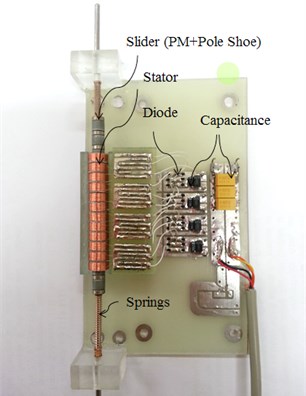
Fig. 10Experimental apparatus to verify the electric characteristics
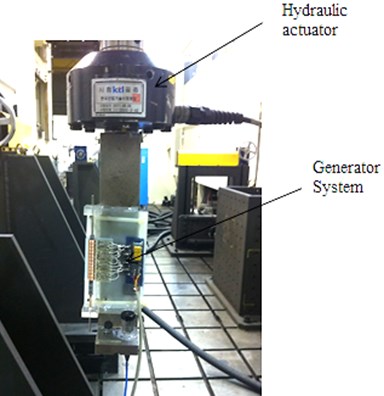
Fig. 11Experimental apparatus to verify the electric characteristics
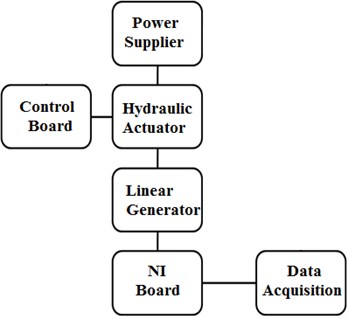
Table 2Experiment conditions according to the input frequency and external load
1st step | 2nd step | 3rd step | 4th step | 5th step | |
Frequency / Hz | 3 | 3.5 | 4 | 4.5 | 5 |
Load / Ω | 560 | 987 | 1966 | 5074 | 11490 |
Load / Ω | 560 | 987 | 1966 | 5074 | 11490 |
Load / Ω | 560 | 987 | 1966 | 5074 | 11490 |
Load / Ω | 560 | 987 | 1966 | 5074 | 11490 |
Load / Ω | 560 | 987 | 1966 | 5074 | 11490 |
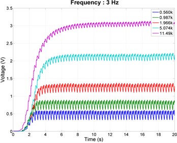
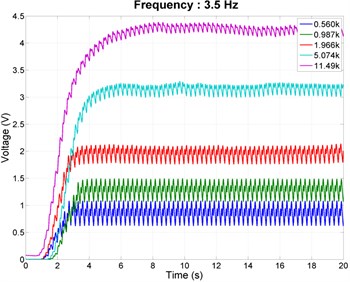
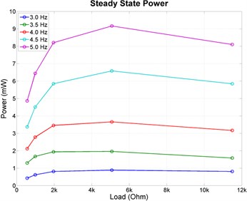
Fig. 13 shows the experimental results which represent the output DC voltage in response to the varying external load. The induced voltage at 3 Hz is not over 3.7 volts which is the minimum voltage.
According to the results, it is impossible for the proposed linear generation system to produce enough DC voltage at 3 Hz. To get stable and enough DC voltage, we can found that the input frequency and external load are more than 4 Hz and 5074 Ω, respectively. In Fig. 11(g), the maximum output DC voltage is produced at input frequency 5 Hz, and external load 11480 Ω. However, the maximum power is produced at external load 5074 Ω as 9.2 mW.
Fig. 12 shows the simulation results to confirm the experiments results. In order to confirm the experiments results, we conducted load-analysis. To match the experiments condition, we modeled the coil-housing as a non-magnetic material in the process of modeling for simulation. According to the simulation results, we can verify error about 8 %.
Fig. 12Simulation results to confirm the experiments results
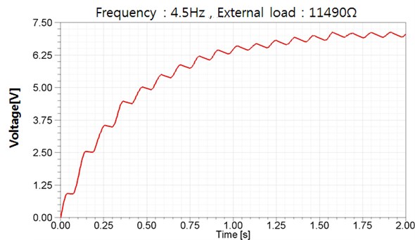
Fig. 13Experiments results: (a)~(e) output DC voltage, (f) steady state output voltage, (g) steady state power
a)
b)
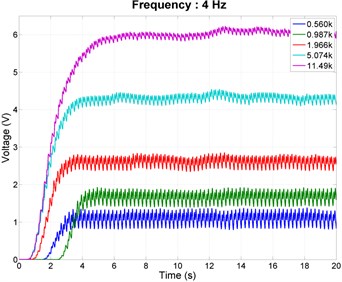
c)
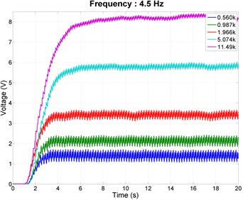
d)
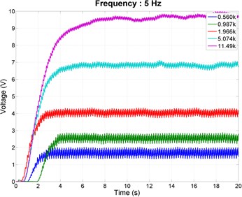
e)
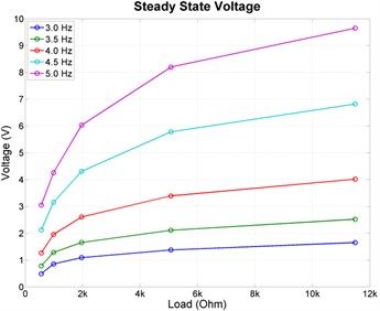
f)
g)
4. Conclusions
In this paper, we proposed internal type small linear generator. We characterized vibrational characteristics by supposing the linear generation system as the base excitation. Also we designed optimal magnetic circuit because it is important to select proper quantity and height of permanent magnet to produce sufficient EMF for recharging the battery. In order to get the optimal quantity and height of permanent magnet, FEA is applied to analyze performance of generator at no-load analysis. Through FEA, we determined the optimal quantity of permanent magnet and its height as 12 EA and 3.5 mm, respectively. Also, we verified the possibility of charging the battery by load-analysis. Lastly, the prototype is manufactured and its experimental result shows the possibility to be in practical use.
References
-
Sang-Yong Jung, Ho-Yong Choi, Hyun-Kyo Jung, Yang-Seung Choi, Kyu-Man Choi Performance evaluation of permanent magnet linear generator for charging the battery of mobile apparatus. Electric Machines and Drives Conference, IEMDC, 2001, p. 516-521.
-
L. I. Anatychuk, V. YA. Mykhailovsky, L. T. Strutynska Self-contained thermoelectric generator for cell phones. Journal of Electronic Materials, Vol. 40, Issue 5, 2011, p. 1119-1123.
-
C. R. Saha, T. O’donnell, N. Wang., P. McCloskey Electromagnetic generator for harvesting energy from human motion. Sensors and Actuators A: Physical, Vol. 147, 2008, p. 248-253.
-
R. Baghbani, M. Ashoorirad A Power generating system for mobile electronic devices using human walking motion. Computer and Electrical Engineering, ICCEE Second International Conference, IEEE Transactions, Vol. 2, 2009, p. 385-388.
-
P. Constantinou, P. H. Mellor, P. Wilcox A model of a manetically sprung vibration generator for power harvesting applications. Electric Machines & Drives Conference, IEEE International, Vol. 1, 2007, p. 725-730.
-
T. Starner, J. A. Paradiso Human generated power for mobile electronics. Low-Power Electronics, 2004, p. 1-35.
-
P. D. Mitcheson, T. C. Green, E. M. Yeatman, A. S. Holmes Architectures for vibration-driven micropower generators. Journal of Microelectromechanical Systems, Vol. 13, 2004, p. 429-440.
-
M. Ruellan, S. Turri, H. B. Ahmed, B. Multon Electromagnetic resonant generator. Industry Applications Conference, IAS, Vol. 3, 2005, p. 1540-1547.
-
M. A. Mueller, N. J. Baker, P. R. M. Brooking, J. Xiang Low speed linear electrical generators for renewable energy applications. 4th International Symposium on Linear Drives for Industry Applications, 2003, p. 29-32.
-
C. R. Saha Modelling theory and applications of the electromagnetic vibrational generator. Sustainable Energy Harvesting Technologies – Past, Present and Future, 2011.
-
W. Zhihua, W. Bowen, W. Miniwei, Z. Huijuan Model and experimental study of permanent magnet vibration-to-electrical power generator. Applied Superconductivity, IEEE Transactions, Vol. 20, Issue 3, 2010, p. 1110-1113.
-
Gwon O-Chang, Kim Ji-Hyun, Jang Ki-Bong, Kim Gyu-Tak The design of tubular type permanent magnet linear synchronous generator for wave power generation. The Korean Institute of Electrical Engineers Conference, 2009, p. 79-81.
-
T. Matsushita, M. Sanada, S. Morimoto, Y. Takeda Study of the configuration and the magnetic pole pitch of the linear generator for wave power generation. IEEJ Transactions on Electrical and Electronic Engineering, Vol. 5, Issue 69, 2005, p. 83-84.
-
T. Von Büren, G. Tröster Design and optimization of a linear vibration-driven electromagnetic micro-power generator. Sensors and Actuators A: Physical, Vol. 135, 2007, p. 765-775.
About this article
This research was supported by Basic Science Research Program through the National Research Foundation of Korea (NRF) funded by the Ministry of Education (2013R1A1A2059513).
