Abstract
To study the characteristics of the coupling vibration between the maglev vehicle and the track beam system, a new type of vibration test bench model was developed. Take the single maglev levitation frame as the study object, the structural characteristics of the maglev vehicle can be adequately considered in the research. Further more, the variable stiffness of the track beam makes the frequency conversion simulation possible. In addition, all types of real track irregularity excitations can be simulated through the test bench dynamics model. Based on the model, the influence of the track beam support stiffness, the track irregularity and the local support deficiency on the levitation control performance was determined using the dynamics simulation method, and the vibration resonance phenomenon of the vehicle/track system was reproduced by the dynamics simulation, too. The developed of the model can increase the research progress of the maglev dynamics research.
1. Introduction
Lots of coupling vibration phenomenon phenomena of between a maglev train and the track has been occurred observed among the development and research courses of the maglev train. During the research period of the Japanese HSST series low low-speed maglev train, the maglev levitation module once occur exhibited oscillation vibration phenomenon due to the low supporting stiffness of the track beam. The German TR series high-speed maglev train could perform levitation steadily on a track with a concrete holder but not on a track with a steel holder. Both the American AMT series maglev train and the Korean UTM series maglev train experienced the coupling vibration problem between the maglev train and the track, which also occurred on the maglev train of . This coupling vibration phenomenon between the vehicle and track beam is the key problem during the development and service course of the maglev train [1-6]. In the early stage, the Bernoulli-Euler tack beam model was usually adopted by the researchers; in this model, the influence of the simply supported beam, the mass ratio between maglev vehicle and track, supporting stiffness of the track beam and the levitation stiffness on the maglev vehicle system dynamics were modeled by representing the maglev vehicle as a movement force or a movement mass block. There are a few of studies on the interactions concerning the vehicle/track system, most of which mainly address the hunting stability and curve negotiation of a maglev vehicle running on the track with a rigid or flexible structure [7-10].
As is well known, the maglev train system is highly nonlinear and unstable system by nature, so all types of research studies have been performed since the maglev train was introduced to the world, including studies of the levitation control system, the design philosophy and the control parameters. The influences of track irregularity on the levitation stability of the maglev train were studied by Sinha, with the system stability of the maglev train using different control methods analyzed via the root loci method [11]. Germany and have proposed the whole control method on a high speed and a low speed maglev train system respectively, and all of the proposed control methods have been applied on the commercial line. After many years of improvement, both of the two methods can already be used in practice [12-14].
The mechanical structure and the levitation control system of the maglev train were primarily separated during above research. Generally speaking, the single electromagnet levitation system was usually taken as the object of study during the research of the levitation control system of the maglev train [15], and only considered the track beam deformation as track irregularity, which can hardly reflect the nature of the track beam. Meanwhile, because the maglev vehicle model was oversimplified, some characteristics of the maglev vehicle were ignored. In contrast, most research on the vehicle dynamics that focus on the coupling vibration of the vehicle/track beam system mainly study the mechanical aspects and lose sight of the levitation control system, and there are only a few of the special research studies that focus on the resonance vibration in the static state of the maglev vehicle. The complex vibration phenomenon cannot be properly understood without considering the levitation-frame / track-beam / levitation-control system together. As a result, the relationship among support stiffness, levitation mass and levitation stability cannot be reflected without considering the entire system [16-18].
In this paper, the mechanical structure and electrical system are combined together, resulting in the creative construction of an electromechanical coupling vibration test bench model. Considering the mechanical structure, the track beam and the levitation control system synthetically perform the electromechanical coupling vibration through the dynamics simulation method.
2. Principle of the model
In the design stage of the maglev vehicle electromechanical coupling vibration test bench model, the characteristics of the vehicle structure, track beam and levitation control system should be considered simultaneously. However, not only do comprehensively considering all these factors let the model comprehensive, but also they go against the specific study because of too many uncontrollable factors. The test bench model in this paper utilized a partial maglev vehicle model, a scale track beam model and the actual levitation control system. Because one maglev vehicle consists of 5 levitation frames and each levitation frame can reflect the characteristics of the maglev vehicle, for simplicity, a single levitation frame was used as the research object.
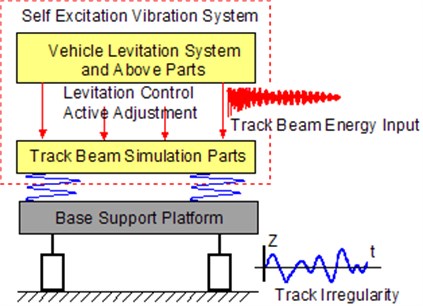
Fig. 1 shows the principle of the test bench, in which, the mass of the levitation system and the parts of the maglev vehicle above it are treated as the levitation mass (simply called the maglev vehicle levitation module), which is coupled with the track beam simulation system through the levitation control system. The track beam simulation part is set on the support platform by supporting springs, and the support platform is set on the basic foundation by four hydraulic actuators, which can produce the specific track irregularity or provide the specific stimulation under study. The maglev vehicle levitation module acts as an energy input to the track beam system, which forms a self-excitation system. Without using the track irregularity input in the track beam simulation part, the static state case of the maglev vehicle can be simulated. In addition, the vibration characteristics of track beam can be simulated by changing the supported mass and the support stiffness of the track beam.
The maglev vehicle is unlike the conventional railway vehicles, which is composed by 5 levitation frames and each levitation frame is an independent system. Therefore, the test bench model which consist one levitation frame model can reflect the actual maglev vehicle/track coupling vibration situation. The test bench model is supported by 4 actuators, which can simulate the track irregularity input by applying the different frequencies of the vibrations. For example, through input the sinusoidal wave with different frequency and phase can simulate the case of the vehicle running through the track with track irregularity. Thus, the model can simulate the actual state of levitation frame moving along the track.
Therefore, the inherent frequency of the track beam can be changed through the change of the stiffness of track beam, which is an approach similarly used to achieve the different deflections of the track beam. By using the different mass and stiffness values of the track beam, the frequency response characteristics can be acquired and research on the response under variable stiffness and variable frequency can be performed. In addition, the vibration characteristics between the track beam and the maglev control system can be simulated. The matching of the track beam and the maglev levitation system enables research on the self-excited vibration, natural frequency and characteristic frequency of the track beam.
Fig. 1Principle of the test bench model
In addition to the characteristics of the track beam, the track irregularity is another factor which needs to be considered. An actual track irregularity will lead to the random or periodic stimulation of the maglev train. In addition, track beam defects and different support positions of the track beam will also cause periodic stimulation, which can also be simulated by different frequency sinusoidal waves using the hydraulic actuator.
3. Dynamics model
The test bench model mainly consists of the basic mechanical structure, the levitation frame mechanical structure and the levitation control system. During the modeling process, the test bench is separated into the mechanical module and the levitation control system module. The test bench mechanical structure, the single levitation frame and the levitation control system are modeled separately to create three sub-models. Based on the 3 sub-models, the single levitation frame mechanical-electrical coupling test bench dynamics model was setup through the substructure method. By separating the mechanical and electric subsystem, the modeling process block diagram can be simplified but also can easily combine the levitation control model and mechanical model.
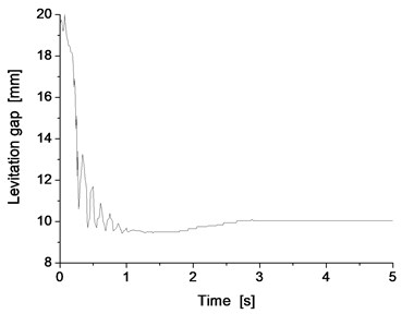
To test the accuracy of the model, a single point maglev levitation control submodel was built first, as shown in Fig. 2, which was completely established in accordance with the actual levitation control procedures, in which the relationship between the maglev levitation control system, track beam and the electromagnets are represented by two balls and the arrow line. The upward ball represents the track beam and the downward ball represents the electromagnet. The distance between two balls in the original state equals to the distance between the electromagnet and track beam when there is no levitation force. The red arrow pointing upward represents the levitation force that acts on track beam and the electromagnet. Through the appropriate choice of sensor, filter and levitation control block diagram, the levitation force can be produced with accurate levitation control. Depending on the different demands, different levitation control block frameworks can be selected. It was tested before starting the calculation, the result is shown in Fig. 3, from it can see that the system can levitation stability with the gap of 10 mm which was the design value, so the levitation control model could reflect the true idea. All the inputs of each levitation control unit are the relative air gap and the absolute vibration acceleration of electromagnet, and the output is the levitation force.
Fig. 2Model of the levitation control point
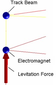
Fig. 3Levitation gap
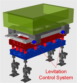
Based on the actual structure of the test bench, the support platform is installed on the basic foundation through four hydraulic actuators, which can provide track irregularity excitation. The track beam is set on the support platform using parallel steel coil springs of alterable support stiffness and mass. The supported stiffness of the springs and the number of springs can be changed during the test, to achieve different supported stiffness values of the track beam. The much more broad range of the supported stiffness values can be considered in the dynamics model than in the real test bench. The levitation control system is installed on the single levitation frame, which connects the test bench and the single levitation frame through the levitation force. There are two modules in the single levitation frame, and each module has an entire levitation electromagnet system. Each levitation electromagnet system is controlled by two levitation control systems that are installed on the two ends of the electromagnet. As a result, there are 4 control systems in each single levitation frame. The maglev vehicle simulation part is supported on the levitation frame by four air springs, and all these items comprise the whole test bench. The test bench dynamics model in SIMPACK software is schematically shown in Fig. 4.
Fig. 4Dynamics model of the test bench
4. Simulation cases
Based on the dynamics model of the test bench, a variety of simulations can be performed, including studies of the track beam characteristics, the levitation control test and so on. Here, the simulation provided analyses of the influence of the track beam support stiffness to the levitation control performance. The simulation also was used to determine the effect of the track irregularities and the track defects to the levitation performance.
4.1. Support stiffness influence
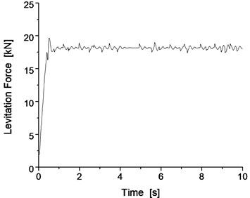
According to the test bench design project, when the stiffness of steel spring is 1 MN/m, the supported stiffness of the track beam can be set to 4, 8, 12, 16 and 20 MN/m. The levitation performances of the test bench system when the support stiffness is 4 and 20 MN/m are shown as examples; the results of the levitation gap, levitation force and vertical vibration of track beam system with different support stiffness are shown in Fig. 5 and Fig. 6.
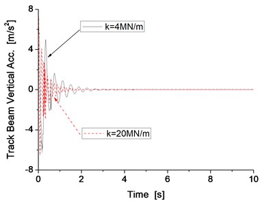
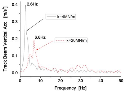
Simulation results indicate that the levitation gap can be maintained at 10 mm and the vibration of the track beam can convergence rapidly in both states when the stiffness value is either 4 MN/s or 20 MN/s. When the stiffness is 20 MN/m, the vibration amplitude is smaller and the convergence occurs more rapidly than in the results when the stiffness is 4 MN/m, which means the levitation performance is better when the support stiffness of track beam is 20 MN/m. Under different stiffness conditions, the inherent natural frequency changes, this will also affect the vibration frequency of the electromagnet. The main vibration frequency of the beam is 2.6 Hz and 6.8 Hz when the stiffness is 4 MN/m and 20 MN/m, respectively.
Fig. 5Levitation gap and levitation force
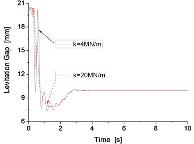
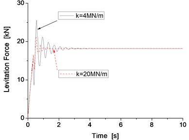
Fig. 6Vertical vibration of the track beam and its main frequency
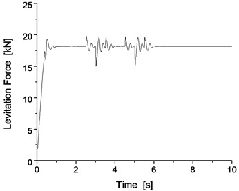
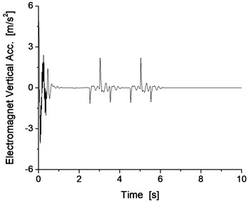
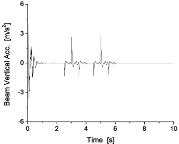
If the match of the mass of the track beam and support stiffness is not possible, the vibration resonance phenomenon of the vehicle/track will occur during the levitation of the maglev vehicle. For example, when the support stiffness of the track beam is 100 MN/m, the results with the mass of the track beam of 1000 kg exhibit oscillations of significant amplitude, as shown in Fig. 7 and Fig. 8.
Obviously, when the support stiffness of the track beam is 100 MN/m, if the mass of the track beam is light, such as 1000 kg, the vibration system of the vehicle/track system cannot converge, resulting in the occurrence of the vibration resonance phenomenon of the vehicle/track system, which also reappears as the vibration resonance phenomenon of the vehicle/track system from the results of the dynamics simulation.
Fig. 7Levitation gap and levitation force
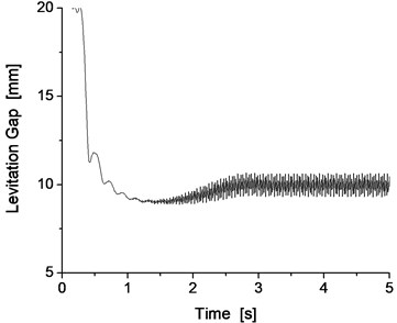
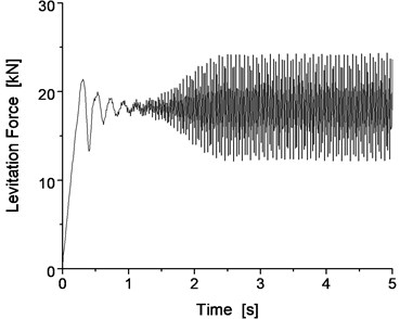
Fig. 8Vertical vibration of the electromagnet and track beam
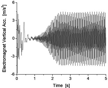
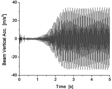
Fig. 9Levitation gap and levitation force

4.2. Effect of track irregularity
The study of the influence of track irregularity on the levitation control system was performed using dynamics simulation, considering the examples of the measured track irregularity of the maglev demonstration line. During the analysis, the track irregularity was transferred into the time domain track irregularity first, and then input into the dynamics model through the hydraulic actuators. In the model and the simulation, the mass of the track beam is 7.5 t and the track beam support stiffness is 12 MN/s. The simulation of the Shanghai track irregularity was performed first, and the results are shown in Fig. 9 and Fig. 10.
For the cases of the Shanghai measured track irregularity, the levitation gap can be changed with the change of the track irregularity and the value of 10 mm can basically be maintained to satisfy the requirement of the levitation control system. The vibration is quite small for the electromagnet and track beam system, with the change value of the vibration acceleration being small and primarily oscillates at the balance position. The results indicate that the levitation control system has good recovery characteristics with the change of the track irregularity.
Fig. 10Vertical vibration of the electromagnet and track beam
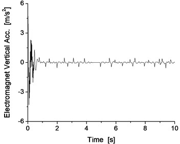
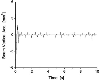
Fig. 11The levitation gap with different K1 with the Shanghai track irregularity
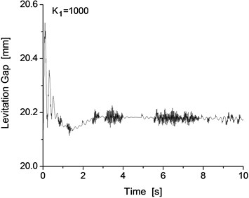
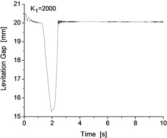
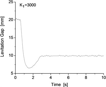

Note that the maglev vehicle cannot pass through the track with the track irregularity in a smooth and steady manner for all levitation control parameter conditions. There are 4 main control parameters , , and , and all these main parameters were used to optimize and implement the levitation system. For the dynamics model of the test bench, the initial value of the control parameters are 3500, 4000, 20 and 10. All the control parameters have a large influence on the performance of the levitation control system. The test bench and the single levitation frame system exhibit good levitation performance under the above parameters, and the levitation performance will change with the change of the levitation control parameters. Taking as an example, different values of will lead to different levitation performances of the system under the Shanghai track irregularity. The levitation gap of the system with different values is shown in Fig. 11, where the value of changes from 1000 to 4000 and the interval is 1000. From Fig. 11, we can clearly see that different values have a significant influence on the levitation gap of the system with the Shanghai track irregularity.
When the value of is 1000 or 2000, the levitation gap is approximately 20 mm, while the design value is approximately 10 mm, so it cannot satisfy the requirement of the levitation system. However, when the value of is between 3000 and 4000, the levitation gap can remain steady at 10 mm and can satisfy the requirement of the levitation system of the maglev vehicle.
4.3. Local track support defect
In addition to the general track irregularity, the track beam may exhibit some local support defect, such as at the connection point of the track. A large vertical irregularity may result from the local support defect, similar to the triangle pitch of the railway track or the irregularity at the connect point of the rail. Such irregularities can occur on the track singly or occasionally; generally speaking, periodical irregularities cannot form. The irregularity used in this section is shown in Fig. 12, and the maximum value of the local vertical defect is 15 mm. To increase the influence of the vertical defect, the case of two consecutive vertical defects was considered, and the response of the test bench system was determined.
Fig. 12Track local support defect
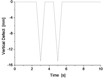
Fig. 13Levitation gap and levitation force
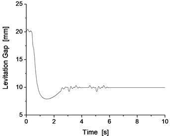
The results for two consecutive vertical defects are shown in Fig. 13 and Fig. 14, which presents the results of the levitation gap, levitation force, electromagnet vibration acceleration and track beam vibration acceleration.
From Fig. 13 and Fig. 14, for two consecutive vertical defects of 15 mm in size, the levitation gap and levitation force can change correspondingly to adapt to the urgent track irregularity. Subsequently, the levitation control system can cause the vibration of the system to quickly dampen through the adjustment of the levitation gap and levitation force. This response also proves that the test bench can perform the vertical defect concern test and that the levitation control system can satisfy the requirements of the 15 mm vertical defect. Because the levitation gap remains at 10 mm, the maglev train can pass the track connection point with a similar vertical defect without the occurrence of any vehicle track contact phenomenon.
Fig. 14Vertical vibration of the electromagnet and the track beam
5. Conclusions
A new type of test bench model was developed that can simulate the coupling vibration of the single levitation frame and the beam.
Based on the dynamics model of the test bench, the influence of the track beam support stiffness, the track irregularity and local track support defect on the levitation control performance was studied through the dynamics simulation method, which was used to simulate the vibration resonance phenomenon of the vehicle/track system. When the match of the support stiffness and the beam mass is not reasonable, the vibration system of the vehicle/track system cannot converge, resulting in the occurrence of the vibration resonance phenomenon of the vehicle/track system.
The test bench model is an innovation in the maglev area, and addresses the gaps of maglev train research. In addition, the test bench model can used to study the characteristics of the track beam to provide theoretical support for beam selection, thereby reducing engineering costs.
The test bench will contribute to maglev vehicle development and accelerate the commercial process of implementing low-speed maglev trains.
References
-
Wang H. P., Li J., Zhang K. Vibration analysis of the maglev guide way with the moving load. Journal of Sound and Vibration, Vol. 305, Issue 4-5, 2007, p. 621-640.
-
Zhao C. F., Zhai W. M. Dynamic characteristics of a single magnet system applied to a low-speed EMS maglev vehicle. Proceeding of International Symposium on Speed-up and Service Technology for Railway and Maglev System, Tokyo, Japan, Vol. 8, 2003, p. 472-477.
-
Zheng X. J., Wu J. J., Zhou Y. H. Effect of spring non-linearity on dynamic stability of a controlled maglev vehicle and guideway system. Journal Sound and Vibration, Vol. 279, 2005, p. 201-215.
-
Han H. S., Yim B. H., Lee N. J., Hui Y. C., Kim S. S. Effects of the guideway’s vibrational characteristics on the dynamics of a maglev vehicle. Vehicle System Dynamics, Vol. 47, Issue 3, 2009, p. 309-324.
-
Yau J. D. Vibration control of maglev vehicles traveling over a flexible guideway. Journal of Sound and Vibraion, Vol. 321, 2009, p. 184-200.
-
Ren Shibo, Arie Romeijn, Kees Klap Dynamic simulation of the maglev vehicle/guideway system. Journal of Bridge Engineering, Vol. 15, Issue 3, 2010, p. 269-278.
-
Yim B. H., Han H. S., Lee J. K., Kim S. S. Curving performance simulation of an EMS-type maglev vehicle. Vehicle System Dynamics, Vol. 47, Issue 10, 2009, p. 1287-1304.
-
Zhao C. F., Zhai W. M., Wang K. Y. Dynamic responses of the low speed maglev vehicle on the curved guideway. Vehicle System Dynamics, Vol. 38, Issue 3, 2002, p. 185-210.
-
Zhou D. F., Li J., Hansen Colin H. Suppression of the stationary maglev vehicle bridge coupled resonance using a tuned mass damper. Journal of Vibration and Control, Vol. 19, Issue 2, 2012, p. 191-203.
-
Hägele Nora, Dignath Florian Vertical dynamics of the maglev vehicle transrapid. Multibody System Dynamic, Vol. 21, 2009, p. 213-231.
-
Sinha P. K. Electromagnetic Suspension Dynamic and Control. Peter Peregrinus Ltd., 1987, p. 50-65.
-
Liu Y. H., Sun G. S., Wei R. The developmental status and future prospects of maglev technology. Maglev, 2006, p. 59-64.
-
Wu X. M. Construction of shanghai maglev demonstration line. Journal of Tongji University, Vol. 30, Issue 7, 2002, p. 814-818.
-
Deng Y. Q. Static levitation stability researches and simulation of maglev. Southwest Jiaotong University, Master thesis, 2005, p. 60-68.
-
Liang X., Luo S. H., Ma W. H., et al. Coupling vibration analysis of single-magnet suspension vehicle-bridge for maglev train. Journal of Traffic and Transportation Engineering, Vol. 12, Issue 2, 2012, p. 32-37.
-
Hironori Hoshino, Erimitsu Suzuki, Takenori Yonezu, Ken Watanabe Examination of vehicle motion characteristics of a maglev train set using a reduced scale model experiment apparatus. Quarterly Report of Railway Technical Research Institute, Vol. 53, Issue 1, 2012, p. 52-58.
-
Lee N. J., Han H. S., Lee J. M., Kang B. W. Maglev vehicle/guideway dynamic interaction based on vibrational experiment. Proceeding of International Conference on Electrical Machines and Systems Seoul Korea, 2007, p. 1999-2003.
-
Yau J. D. Response of a maglev vehicle moving on a series of guideways with differential settlement. Journal of Sound and Vibration, Vol. 324, Issue 3-5, 2009, p. 816-831.
About this article
We thank the New Century Excellent Talents program in University (Grant No. NCET-11-0712) for their aid and support, the China Postdoctoral Science Foundation (Grant No. 2013M540715), the “Sishi” Star program of Southwest Jiaotong University.
