Abstract
Based on the dynamic characteristics obtained with a three-dimension finite element method, a reduced mechanical model and parameters for the ship lift can be modified and obtained. Simulated analysis shows that the reduced mechanical model can adequately represent the dynamic characteristics and earthquake responses. The reduced mechanical model can be used to control the seismic whiplash effect of the top workshop of the ship lift with intelligent control methods. A modified Bingham model was proposed to simulate the machinery property of a magnetorheological smart damper. A roof intelligent isolation system was also proposed. Seismic simulation analysis of the ship lift was conducted using a fuzzy control strategy. Simulation analysis results show that the fuzzy semi-active control with a magnetorheological smart damper is beneficial in suppressing the seismic whiplash effect on the top workshop and confirm that the fuzzy semi-active control strategy is valid in this scenario.
1. Introduction
The Three Gorges Project is the largest water conservancy project in the world. The project is located in the middle reach of the Yangtze River [1]. Navigation construction consists of a double-line five-step ship lock and a vertical ship lift, which has been under construction since 2008 and will be used predominately for passenger ships [2, 3]. The ship lift will shorten the time required for ships to pass through the dam from more than 3 hours to approximately 1 hour. The reinforced concrete platform at the top of the ship lift’s tower has an enormous stiffness mutation, which will cause a strong seismic whiplash effect on the top lift workshop. Conventional seismic design methods to suppress the seismic whiplash effect on the workshop are impractical in this scenario due to the difficulty in setting a variety of support systems on the top of the ship lift frame. However, the use of intelligent control methods can inhibit the seismic whiplash effect at the top of the ship lift.
Conventional civil engineering structures are designed such that the mass and rigidity of the structure can resist uncertain dynamic loads. The need of adaptability to resist uncertain loads increased the safety levels. The strong desire for better utilization of new materials and lower costs motivated the development of new concepts for protecting structures. Alternative approaches, such as passive, semi-active and active controls, have been proposed and developed to protect structures from earthquakes and severe winds. Passive control devices, such as tuned mass dampers [4], tuned liquid dampers [5, 6] and electromagnetic friction dampers [7], do not require an external power source. Among the passive devices, base isolation systems are mostly researched and widely applied in practice. Base isolation systems are effective in reducing the inter-story displacements. However, the passive control system has limited practical application because it is not able to adapt to different structural changes or varying usage patterns and loading conditions. An active control scheme uses a power source to drive actuators that apply forces to a primary structure in a prescribed manner. These forces can be used to both add and dissipate energy in the structure. Active control strategies for structural systems have been developed as one means by which to minimize the effects of environmental dynamic loads. Active control systems require external power, routine maintenance, high-performance digital signal processors and bulky power amplifiers to drive the actuators, and they may eventually become potentially unstable [8]. Semi-active control devices have received significant attention in recent years because they are inexpensive and offer the adaptability of active control devices without requiring the associated large power sources [9, 10].
Semi-active control strategies combine active and passive control schemes and attempt to offer the advantages of both systems with better performance. Smart damping technology is a type of semi-active control that employs variable dampers, for example, variable orifice dampers, magnetorheological (MR) fluid dampers, and electrorheological (ER) fluid dampers [11, 12]. Smart damping technology assumes the positive aspects of both passive and active control devices; it can provide increased performance over passive control without the concerns of energy and stability associated with active control. MR dampers are semi-active control devices that employ MR fluids to produce controllable dampers [13]. Because MR dampers are not sensitive to contaminants, they are relatively inexpensive to manufacture. Other benefits of MR dampers include their small power requirements, reliability and stability [14]. One challenge in the application of semi-active technology is the development of nonlinear control algorithms that can be implemented on full-scale structures. Various control algorithms used in recent semi-active control studies were considered for this study, including genetic algorithms [15, 16], neural network algorithms [17] and fuzzy logic control algorithms [18].
To develop control algorithms that can fully utilize the unique features of the MR damper, models must be developed that can adequately characterize the damper’s intrinsic nonlinear behavior. A new model was proposed that effectively portrays the behavior of a typical MR damper. Comparisons between the passive-off, passive-on and fuzzy logic control algorithm results for the MR damper indicate that the fuzzy logic control algorithm is adequate for control design and analysis.
2. A simplified mechanical model of the ship lift structure
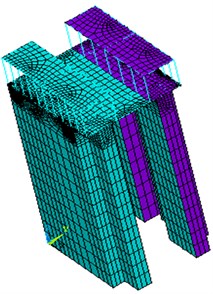
To use an intelligent control design for the top of the workshop, it is necessary to create a simplified mechanical model for calculations involving the ship lift. Because the structure is located in a central seismic gap, half of the structure is required for the calculations. A three-dimensional finite element model of the Three Gorges ship lift structure is shown in Fig. 1. The concrete bulk density is 25 kN/m3, the elastic modulus is 30 GPa, and the Poisson’s ratio is 0.167.
Fig. 1The three-dimensional finite element model of the ship lift structure
2.1. Mass matrix
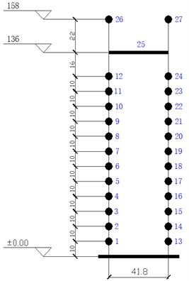
The Three Gorges ship lift was discretized into a 27 node series concentrated mass system, as shown in Fig. 2. The ship lift is 158 m high and 41.8 m wide. Structural dynamic characteristics calculated using the three-dimensional finite element model and the simplified concentrated mass model were used to adjust the structural parameters of the ship lift and to ultimately determine the parameters of the equivalent simplified structure.
Fig. 2Simplified lumped mass model of the ship lift structure
For the ship lift’s two-dimensional series multi-degree of freedom system, the mass matrix is a 27×27 diagonal matrix, where equals the diagonal of the matrix [, ,…, ]. The diagonal elements are the mass of each node layer’s structural and non-structural components. Table 1 shows the Three Gorges ship lift’s node concentrated mass.
Table 1Ship lift node concentrated mass (kt)
Node number | Mass | Node number | Mass | Node number | Mass |
1 | 5.4923 | 2 | 5.4923 | 3 | 5.4923 |
4 | 5.4923 | 5 | 5.4923 | 6 | 5.4923 |
7 | 5.4923 | 8 | 5.4923 | 9 | 5.4923 |
10 | 5.4923 | 11 | 5.4923 | 12 | 7.1400 |
13 | 5.4923 | 14 | 5.4923 | 15 | 5.4923 |
16 | 5.4923 | 17 | 5.4923 | 18 | 5.4923 |
19 | 5.4923 | 20 | 5.4923 | 21 | 5.4923 |
22 | 5.4923 | 23 | 5.4923 | 24 | 7.1400 |
25 | 3.5122 | 26 | 3.4274 | 27 | 3.4274 |
2.2. Stiffness matrix
For the Three Gorges ship lift’s multi-degree of freedom model, the stiffness matrix can be obtained through the following method:
1) The node layer (1, 2, ...) of the Three Gorges ship lift’s finite element model is applied to the unit horizontal force 1;
2) The layer’s displacement (1, 2, ...) is calculated using the finite element software, and then the node layer’s nominal displacement is calculated and the compliance coefficients (, 1, 2, ...) are obtained;
3) The flexibility coefficients (, 1, 2, ...) are integrated to obtain the compliance matrix ;
4) The inverse of the flexibility matrix is used to determine the stiffness matrix , i.e., .
2.3. Damping matrix
The material damping matrix is often assumed to be a Rayleigh-type damping. The Rayleigh damping is proportional to a combination of the mass and the stiffness matrices [19]:
where and are coefficients of mass damping and stiffness damping, respectively; and are the natural period of vibration for the first and second natural modes, respectively; and and are factors of the viscous damping for the structure, which are often assumed to be the same constant value.
2.4. Analysis of the dynamic characteristics
The finite element method was used to calculate the natural frequencies in the Three Gorges ship lift structure. A total of 8 natural frequencies are shown in Table 2: the top 5 natural frequencies along the vertical direction of the river ( direction) and the top 3 natural frequencies along the parallel direction of the river ( direction). The values calculated using the simplified model are consistent with the values calculated using the finite element model.
Table 2Comparison of the Three Gorges ship lift natural frequencies
Modal number | Finite element model (Hz) | Simplified model (Hz) | Deviation |
1 | 0.4511 ( direction) | 0.4577 | 1.5 % |
2 | 0.7728 ( direction) | 0.7824 | 1.2 % |
3 | 0.8124 ( direction) | 0.8191 | 0.8 % |
4 | 1.2299 ( direction) | 1.1993 | 2.5 % |
5 | 1.2429 ( direction) | 1.2606 | 1.4 % |
6 | 1.3189 ( direction) | 1.2757 | 3.3 % |
7 | 2.1314 ( direction) | 2.0788 | 2.5 % |
8 | 2.6024 ( direction) | 2.5714 | 1.2 % |
To further validate the simplified mechanical model of the ship lift structure, a seismic response analysis was conducted on the Three Gorges ship lift structure using the three-dimensional finite element model and the simplified mechanical model.
The differential equation for motion of a finite element system under a seismic motion of the ground in a well-known matrix form is [20]:
where , and are mass, damping and stiffness matrices, respectively; , and are vectors for the nodal accelerations, nodal velocities and nodal displacements, respectively; and are the ground vector of nodal accelerations.
The earthquake excitation is an artificial earthquake wave applied at the Three Gorges Dam, with a peak acceleration of 4.0 m/s2, as shown in Fig. 3.
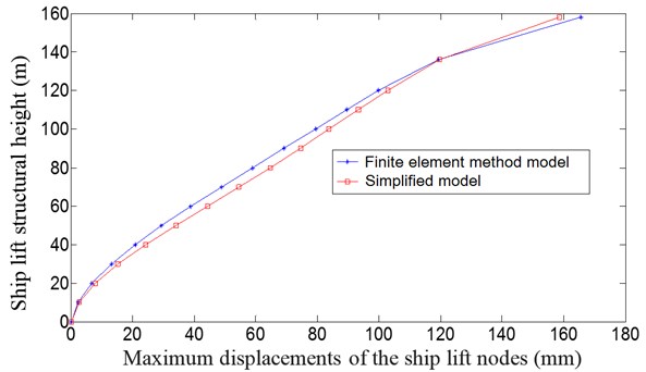
Fig. 4 is the comparison between the maximum displacements for each node layer using the three-dimensional finite element analysis method and the simplified model analysis method. The maximum displacement responses at 136 m using the finite element model and the simplified model are 119.3 mm and 119.5 mm, respectively, and at 158 m, the maximum displacement responses are 165.6 mm and 158.2 mm, respectively.
The maximum displacement responses calculated using the simplified model are similar to the results obtained using the finite element model (Fig. 4). The above analysis and calculation show that the simplified mechanical model can accurately reflect the dynamic characteristics and the seismic responses of the ship lift structure and can be used for the intelligent control design of the ship lift structure with a seismic whiplash effect.
Fig. 3The time-history curve of an artificial earthquake wave
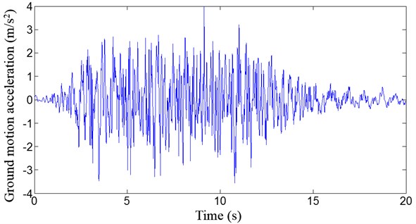
Fig. 4Comparison of the maximum displacements of each node layer
3. Modified Bingham model
MR fluids are developed by the Lord Corporation and have many positive characteristics, including high yield strength, low viscosity and stable hysteretic behavior over a broad temperature range. When a magnetic field is applied to the fluids, particle chains form and the fluid becomes a semisolid, exhibiting Bingham plastic behavior [21]. The MR smart damper device is simple, small in volume, can observe continuous change, has a rapid response speed (up to milliseconds), is durable, is able to apply a damping force and has a low energy consumption. This method of structural vibration control represents a new generation of highly efficient dampers and of semi-active control devices.
To fully utilize the unique features of the device, a model was developed to effectively reproduce the behavior of the MR damper. A modified Bingham model for the MR smart damper was developed (Fig. 5). The model consists of a Bingham unit (a Coulomb friction element in parallel with a dashpot) in series with a spring element. The spring element can be regarded as energy storage equal to the equivalent axial stiffness, and the equivalent axial stiffness of the damper can be considered as the accumulator stiffness and the shear modulus effect before the magnetorheological fluid yield.
Fig. 5A modified Bingham model for the MR damper
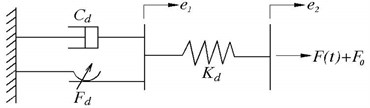
The damping force can be expressed as:
where is the plastic viscosity; is the shear rate; is the frictional force; and are the sliding displacement and the total displacement of the damper, respectively; is the accumulator stiffness; and is the output force deviation of the damper caused by the accumulator.
4. Fuzzy semi-active control design
Fuzzy control has obvious advantages over traditional proportional-integral-derivative (PID) control. Because fuzzy control is essentially a control strategy to replace the tasks performed by the operation personnel with computers, it can avoid the complications associated with a mathematical model. It is difficult to establish mathematical models for large delay, time-varying and nonlinear systems with random disturbance, making traditional PID control methods invalid.
4.1. Fuzzy control strategy
A fuzzy control system is a control system based on fuzzy logic that analyzes analog input values in terms of logical variables. For structural vibration control, a fuzzy control force is obtained by the fuzzy inference operation. The basic idea of fuzzy reasoning is based on the fuzzy control rules applied to the input variables to determine the value of the output variable. The control process is as follows: first, use a sensor measurement system to obtain the vibration response; second, the input signal controller detects the detection signal, and the controller calculates the control signal according to the fuzzy control theory; and finally, fuzzy logic is imposed on the control force to control the dynamic responses of the structure by a control device. Fuzzy control system design is based on empirical methods, and the general process follows the next three steps.
(1) Define the input and output variables and membership functions.
In the process of structural vibration control, the isolation layer velocity and interlayer acceleration are defined as the inputs, the fuzzy control force is defined as output, and the fuzzy membership function uses a triangular membership function. The membership function curves are shown in Fig. 6.
(2) The rule set.
In the fuzzy inference system, the content does not depend on the parameters of the structure itself; instead, the control standards are usually determined according to expert experience and can be adjusted based on the actual situation. The fuzzy control rules used in this paper are shown in Table 3.
(3) Fuzz input and defuzzify output.
A fuzzy set is defined for the input variables. The outputs generated using the above rules can be defuzzified using a discrete centroid computation.
Fig. 6Membership function curves
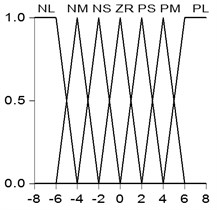
Table 3Fuzzy control rules
NL | NM | NS | ZR | PS | PM | PL | |
NL | PL | PL | PM | PM | ZR | NS | NS |
NM | PL | PL | PM | PM | ZR | NS | NM |
NS | PL | PL | PS | PS | ZR | NM | NM |
ZR | PL | PM | PS | ZR | NS | NM | NL |
PS | PM | PM | ZR | NS | NS | NL | NL |
PM | PM | PS | ZR | NM | NM | NL | NL |
PL | PS | PS | ZR | NM | NM | NL | NL |
where NL: Large negative; NM: Medium negative; NS: Small negative; ZR: Zero; PS: Small positive; PM: Medium positive; and PL: Large positive | |||||||
4.2. Semi-active control strategy
To determine the MR smart damper semi-active control effect on the fuzzy active control effect, MR smart damper parameters, were introduced. The parameters use a semi-active control strategy of “off-on” for easy implementation and for a better damping effect. The parameters are as follows:
where and are the maximum and minimum forces that the MR damper can provide, respectively; is the semi-active control force; and is the actual force of the MR damper.
5. Fuzzy semi-active control simulation analysis
A MR intelligent isolation system is set between the top of the ship lift structure column and the roof of the structure. The isolation system is composed of a MR damper and isolation cushions (Fig. 7). The total lateral stiffness of the cushions is 1/16 of the total column lateral stiffness, i.e., 1.0×10⁷ N/m.
Table 4 shows that structural control can effectively suppress the seismic whiplash effect of the structure. All control methods can reduce the storey drift and the moment response at the bottom of a column while simultaneously improving the safety performance of the structure. The control effect of the passive-off, the passive-on and the fuzzy semi-active control method is approximate each other. But the fuzzy semi-active control method achieved the best control effect. This method had almost the minimum lateral storey drift, interlayer velocity and acceleration and seismic moment reaction. The isolation cushions guarantee the safety of the ship lift structure, especially the safety of work shop. The consequent the lateral displacement of the isolation layer is large. However, the MR dampers can effectively reduce the lateral displacement of the isolation layer. The isolation system fully utilizes the advantage of the isolation cushions and the MR dampers.
Fig. 7MR intelligent isolation system
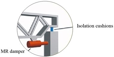
Table 4Simulation analysis results
No control | Control | ||||
Passive isolation | Passive-off | Passive-on | Fuzzy Semi-active | ||
Maximum displacement at the top of column (mm) | 119.5 | 94.2 | 94.2 | 94.5 | 94.5 |
Maximum displacement at the top of workshop (mm) | 158.2 | 107.9 | 108.0 | 109.3 | 109.3 |
Maximum displacement at the roof (mm) | – | 266.9 | 264.5 | 251.2 | 249.6 |
Maximum lateral storey drift at the top of workshop (mm) | 62.6 | 21.0 | 20.8 | 20.1 | 20.3 |
Maximum lateral displacement of the isolation layer (mm) | – | 266.9 | 264.5 | 251.2 | 250.8 |
Maximum lateral interlayer velocity at the top of workshop (m/s) | 0.491 | 0.316 | 0.314 | 0.304 | 0.307 |
Maximum lateral velocity of the isolation layer (m/s) | – | 0.869 | 0.864 | 0.828 | 0.827 |
Maximum lateral interlayer acceleration at the top of workshop (m/s2) | 5.282 | 4.520 | 4.506 | 4.391 | 4.407 |
Maximum lateral acceleration of the isolation layer (m/s2) | – | 4.776 | 4.750 | 4.622 | 4.634 |
Maximum bending moment at the bottom of column (KN·m) | 12637 | 5465 | 3478 | 3460 | 3346 |
where: Passive-off: MR dampers remain without electricity and MR control force is minimum; Passive-on: MR dampers remain energized and MR control force is maximum | |||||
Fig. 8Maximum storey drift comparison
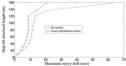
Fig. 8 shows the maximum storey drift comparison. The results of the simulation analysis revealed that the MR intelligent isolation system with a fuzzy semi-active control method reduced the storey drift by 70.1 % compared to the structure without the control. Therefore, the fuzzy semi-active control strategy is an effective structural control strategy, and the MR intelligent isolation system is a reliable and effective control system.
6. Conclusions
In this work, a MR intelligent isolation system was proposed for the Three Gorges ship lift, along with a semi-active structural vibration control strategy for the seismic protection of the ship lift structure. The proposed method is able to provide better damage reduction than traditional methods. The main conclusions that can be drawn from this investigation are as follows:
1) The equivalent reduced mechanical model can be established using the three-dimensional finite element model of the Three Gorges ship lift. The calculation results show that the reduced mechanical model can reflect the dynamic characteristics and seismic responses of the ship lift structure and can be used for intelligent control design of the seismic whiplash effect of the ship lift structure.
2) Fuzzy semi-active control achieved the best control effect. The proposed semi-active approach is a practical and effective control solution.
3) The proposed smart semi-active system has the simple structure with little power supply, and has adaptability to external loads by itself. These are important benefits of using the smart semi-active system.
References
-
Xu X. B., Tan Y., Yang G. S., et al. Three Gorges project: effects of resettlement on nutrient balance of the agroecosystems in the reservoir area. Journal of Environmental Planning and Management, Vol. 54, Issue 4, 2011, p. 517-537.
-
Niu X. Q., Tong D., Song W. B. The design of double-line five step ship-lock of Three Gorges project. Engineering Sciences, Vol. 9, Issue 3, 2011, p. 74-81.
-
Zheng S. R. Overview of three Gorges project design. Electric Power, Vol. 42, Issue 3, 2009, p. 1-5.
-
Zhang Z., Balendra T. Passive control of bilinear hysteretic structures by tuned mass damper for narrow band seismic motions. Engineering Structures, Vol. 54, 2013, p. 103-111.
-
Love J. S., Tait M. J. A preliminary design method for tuned liquid dampers conforming to space restrictions. Engineering Structures, Vol. 40, 2012, p. 187-197.
-
Chakraborty S., Debbarma R., Marano G. C. Performance of tuned liquid column dampers considering maximum liquid motion in seismic vibration control of structures. Journal of Sound and Vibration, Vol. 331, Issue 7, 2012, p. 1519-1531.
-
Dai H. Z., Liu Z. P., Wang W. Structural passive control on electromagnetic friction energy dissipation device. Thin-Walled Structures, Vol. 58, 2012, p. 1-8.
-
Aly A. M. Vibration control of buildings using magnetorheological damper: a new control algorithm. Journal of Engineering, Vol. 596078, 2013, p. 1-10.
-
Aldemir U., Yanik A., Bakioglu M. Control of structural response under earthquake excitation. Computer-Aided Civil and Infrastructure Engineering, Vol. 27, Issue 8, 2012, p. 620-638.
-
Quinonero F. P., Massegu J. R., Rossella J. M., et al. Semiactive-passive structural vibration control strategy for adjacent structures under seismic excitation. Journal of the Franklin Institute, Vol. 349, Issue 10, 2012, p. 3003-3026.
-
Weiss K. D., Carlson J. D. A growing attraction to magnetic fluids. Machine Design, Vol. 66, Issue 15, 1994, p. 61-64.
-
Halsey T. C. Electrorheological fluids. Science, Vol. 258, Issue 5083, 1992, p. 761-766.
-
Cho S. W., Jung H. J., Lee I. W. Smart passive system based on magnetorheological damper. Smart Materials and Structures, Vol. 14, Issue 4, 2005, p. 707-714.
-
Jansen L. M., Dyke S. J. Semiactive control strategies for MR dampers: comparative study. Journal of Engineering Mechanics, Vol. 126, Issue 8, 2000, p. 795-803.
-
Xue X., Zhang L., Wu X., et al. Structural semi-active control based on genetic algorithm using magnetorheological damper with time delay. Journal of Xi’an Jiaotong University, Vol. 44, Issue 9, 2010, p. 122-127.
-
Chen C. W., Chen P. C., Chiang W. L. Modified intelligent genetic algorithm-based adaptive neural network control for uncertain structural systems. Journal of Vibration and Control, Vol. 19, Issue 9, 2013, p. 1333-1347.
-
Fang M. C., Lee Z. Y. Portable dynamic positioning control system on a barge in short-crested waves using the neural network algorithm. China Ocean Engineering, Vol. 27, Issue 4, 2013, p. 469-480.
-
Ali S. F., Ramaswamy A. Optimal fuzzy logic control for MDOF structural systems using evolutionary algorithms. Engineering Applications of Artificial Intelligence, Vol. 22, Issue 3, 2009, p. 407-419.
-
Zhou H. M., Wang C. Y., Tang D. W., et al. Dynamic analysis of the lengthened shrink-fit holder and cutting tool system in high-speed milling. Machining Science and Technology, Vol. 16, Issue 2, 2012, p. 157-172.
-
Petrov A. Y., Geoffrey Chase J., Sellier M., et al. Non-identifiability of the Rayleigh damping material model in magnetic resonance elastography. Mathematical Biosciences, Vol. 246, Issue 1, 2013, p. 191-201.
-
Spencer Jr. B. F., Dyke S. J., Sain M. K., et al. Phenomenological model for magnetorheological dampers. Journal of Engineering Mechanics, Vol. 123, Issue 3, 1997, p. 230-239.
About this article
This research is financially supported by National Natural Science Foundation of China under Grant No. 51008011 and by the China Scholarship Council under Grant No. 201206025022.
