Abstract
From the sensitivity of the FBG center wavelength changing with the macro-elastic modulus and the instantaneous fracture strain wave on the surface of carbon fiber reinforced plastics (CFRP) composite, we investigate the correlation between the macro-elastic modulus (the changing rate of the FBG center wavelength during the stretching process) and the fracture status of CFRP specimen. An FBG staged monitoring method based on modulus/strain wave coupling properties designed to monitor tensile fracture state of composite has been proposed. By monitoring the change of macro-elastic modulus during the stretching process, the damage state of composite in a macro perspective is obtained; when the internal damage reaches a critical state, the fracture distribution status of CFRP specimen is captured by monitoring the strain wave response induced by stress relaxation in different locations. Simulated analysis and experimental results in this paper show that the proposed FBG staged monitoring method can achieve the identification of the damage state and the breakage position of CFRP composite effectively, with a good prospect.
1. Introduction
With the development of aviation and aerospace, carbon fiber composite material has become one of the main aeronautical materials because of its superior performance such as light weight, high strength, being designable and so on. In recent years, with the increasing demand of advanced carbon fiber composite such as carbon fiber reinforced plastics (CFRP), CFRP composite has settled some technical difficulties which can not be solved by a single material, and has been widely used in the vertical stabilizer, fuselage and wing of aircraft. However, cracks, delamination and other damages will be formed in CFRP composite during the period of the manufacture and long-term use. If they can not be detected in time, these damages will lead to rapid destruction of the structure, and cause accidents. As the major injury form of composite, the fracture damage monitoring has a positive meaning [1-5].
At present, the main non-destructive methods of monitoring the internal crack state of carbon fiber composite material structure include ray detection [6, 7], ultrasonic detection [8, 9], acoustic emission detection [10], etc. Ray detection has the advantage of intuitive image, and easy judgment of the nature and the size of the defects, but it has low sensitivity to detect tiny cracks and higher detect cost. Ultrasonic detection has a large detecting thickness, high sensitivity and low cost, but it has a certain detecting blind spot in near-field and the test pieces are susceptible to be polluted. Compared with the above detection methods, strain wave response has advantages of high sensitivity, large coverage area and high performance of detecting the specimen in operating state. Therefore, the strain wave response method is widely used in the fracture monitoring of carbon-fiber composite structure, which is the mainstream technology in the field of composite structural health monitoring at this stage.
As the advantages of light and small, corrosion resistance, good stability, absolute measurement, excellent multiplexing capability, etc., the composite structural health monitoring based on fiber-optic sensor, especially fiber Bragg grating (FBG) has become a new hot spot focused by the current domestic and international aerospace researchers [11-15]. In 1970s, C1aus has buried the fiber into CFRP materials first time, making materials with capabilities of sensing and detecting damages. Subsequently, the Grumman Corporation has monitored the damage and strain of the wing of F-18 using FBG sensors. The Martin Company has applied the fiber grating sensor network to monitor the strain and the temperature of X-33 space shuttle. At the same time, the health monitoring system based on FBG sensor network also has been applied on composite rocket motor case of DALTA II. But none of the above applications has achieved the whole process monitoring of fracture in carbon fiber composite.
Based on the changing mechanisms of macro-elastic modulus and surface strain characteristic of CFRP tensile specimen during the fracture process, we have introduced the strain-sensitive features of FBG into the CFRP fracture monitoring field. Using the high sensitivity of FBG to the macro-elastic modulus change and the tensile strain wave released during fracture, a CFRP fracture monitoring system based on FBG has been designed, which is better suited for composite fracture damage monitoring during the whole process, with a good prospect.
In the following, the working principle of the proposed FBG carbon fiber composite fracture monitoring method is first demonstrated through rigorous theoretical and emulational development. Afterward, an experimental validation of the measuring principle is described and discussed, followed by a brief conclusion.
2. Basic principle of the fracture-detection technique
2.1. Failure mechanism for CFRP material
The strength theory of composite includes macro-strength theory and micro-strength theory. Maximum stress theory, Tsai-Hill theory, Maximum strain theory, etc. belong to the macro-strength theory category mainly for failure criteria and intensity index. Mixed effect and synergistic effect of composite belong to the micro-strength theory category mainly for the research of the compounding effect of each phase of composite. Because the composite is composed of various components, a linear superposition of composite characteristics is used to represent the mechanical properties of composite, which constitutes the mixed effect of composite.
According to the balance of force on fiber segments and assumptions, the axial tensile stress of fiber segment and the shear stress of the interface are deduced by [16, 17]:
where is the effective radius of fibers, is the characteristic parameter of interfaces, is the overall strain of composite, is the elastic modulus of fiber, and .
The characteristic parameter of interfaces is expressed as:
where is the Poisson ratio of matrix and is the effective radius of matrix.
The stress concentration factor indicates the stress fluctuation degree of the neighboring non-broken fibers caused by the load released from broken fibers, and it is an important parameter to describe the stress transfer among fibers, which is defined as follows:
where is local stress on non-broken fibers, which is composed of the stress induced by initial load on non-broken fibers and the extra stress released by broken fibers.
The crack formation and propagation process on external force involves the formation of cracks, the plastic deformation of crack tips and crack propagation, which can become strong strain wave emission sources. A perceptible strain wave signal with no high amplitude is generated during the crack formation, while the strain wave emission caused by crack propagation is much stronger than the one generated by crack formation. When the cracks are growing into the critical state, the composite is coming into an unstable stage, that is, the fast break stage. At this time, strain wave emission signals are more intense, resulting in stress relaxation, such as the sound heard by ears which can be produced in fracture toughness tests, so the formation and expansion of cracks can be as strong strain wave emission sources [18-23].
2.2. FBG strain features
According to Hooke theorem, when the axial stress is imposed on FBG, the wavelength shift of FBG induced by stress is expressed as [24, 25]:
where, is the longitudinal stretching amount of optical fibers, is the change of optical fiber diameter induced by longitudinal stretching, is the period of grating, is the longitudinal length of grating, is the effective refractive index of grating, is the elastic-optic effect, is the waveguide effect, and is the longitudinal stretching strain.
Using the axial symmetry of optical fiber () and the conditions of even fiber in uniform tensile process, the longitudinal strain sensitivity of wavelength shift caused by uniform axial strain is given by:
where, is the center wavelength of FBG, is the elastic coefficient of optical fiber, is the Poisson’s ratio of optical fiber, is the effective elastic-optic constant, is the sensitivity coefficient of relative FBG wavelength shift. Based on the analysis above, the sensitivity coefficient of FBG longitudinal strain is only decided by the material itself and the effective refractive index of reverse coupled-mode. As , the relationship between wavelength shift and strain of the FBG with the center wavelength of 1531 nm is 1.194×10⁻³ nm/με.
2.3. Mechanism of the proposed fracture-detection method based on FBGs
With the continuous stretching of CFRP tensile specimen, some damages such as delamination, fracture, etc. gradually appear in fiber and matrix part of composite which has been out of the elastic stage. It makes the elastic modulus of fiber and matrix decrease, resulting in the decreasing of macro-elastic modulus of composite with the increasing of damages. When the internal damage reaches a critical state, the interfacial debonding and the sudden fiber rupture will release a lot of energy, resulting in stress relaxation. As a major strain wave emission source, the formation and the propagation of cracks are related to the plastic deformation of materials, and they are the main reason for structural failure. Therefore, the strain wave emission induced by stress relaxation is an important research object and basis of fracture mechanics and structural failure prediction.
In this paper, the FBG strain sensitivity has been applied to monitor the fracture status of CFRP composite, and an FBG staged monitoring method based on modulus/strain wave coupling properties has been proposed. The entire process of the tensile fracture monitoring is divided into two stages. In the first stage, by monitoring the change of macro-elastic modulus during the stretching, the damage state of composite in a macro perspective has been obtained, that is, with the continuous stretching of CFRP specimen, the micro-damage of composite is increasing and the local elastic modulus nearby the crack damages is decreasing; in the second stage, when the internal damage has reached a critical state, by monitoring the strain wave response in different locations of the specimen induced by stress relaxation, the fracture distribution status of CFRP tensile specimen during the tensile process is obtained. Through the above processes, a real-time online monitoring of fracture status has been achieved.
3. Finite-element analysis
3.1. Finite-element model
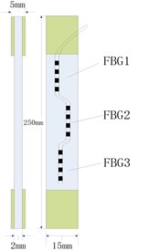
To verify the relationship between the local stiffness (elastic modulus) of CFRP composite and fracture damage status, the numerical analysis of the first stage of tensile fracture monitoring process is carried out using the finite element analysis software PATRAN/NASTRAN. The structure form of CFRP is the typical axial tensile specimen, the type of CFRP is T700/QY8911, and the stacking sequence is [45/0/–45/90/0/45/0/–45/0] S. The size of specimen is 250×15×2 mm, and the size of strengthening sheets located at both ends of specimen is 55×15×1.5 mm. The mechanical parameters of the specimens are shown in Table 1.
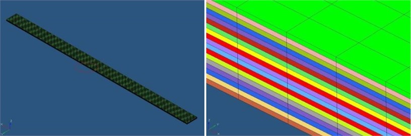
Fig. 1The finite element mesh situation of the CFRP tensile specimen: a) The overall view of finite element mesh, b) Crack processing
a)
b)
Table 1The mechanical parameters of CFRP composite tensile specimens
Tensile strength (MPa) | Tensile modulus (GPa) | Compressive strength (MPa) | Compressive modulus (GPa) | Shear strength (MPa) | Shear modulus (GPa) | Poisson ratio | Interlaminar shear strength (MPa) | |
0° | 2946 | 130 | 1380 | 130 | 156 | 6.36 | 0.289 | 122 |
90° | 70.9 | 10.4 | 245 | 10.4 |
Considering the accuracy and efficiency of simulation and other factors, hexahedral element is used in the simulation of CFRP tensile specimen and the finite elements at crack location are processed in the manner of Node Knockout. Meanwhile, considering the oneness of structure, the interlaminar crack is processed by node overlap.
After the tensile specimen model is established, mesh generation is performed. Because the region with crack is the weakest one and most prone to damage, the mesh refinement is applied in the crack region by hexahedral meshes. Fig. 1 illustrates the finite element mesh situation of the CFRP tensile specimen.
In the simulation, the load mode is stretching along the direction of the tensile specimen. One side is clamped, and the other side is stretched. 6 DOF of the fixed end is all restrained and the applied load is 3000 N.
3.2. Results
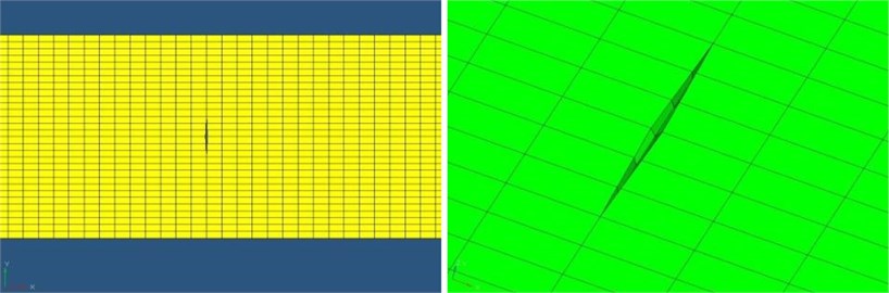
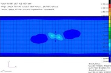
The established model was submitted to NASTRAN for calculating. Fig. 2 shows the strain contour of the crack region on the unilateral 9th laminate of CFRP tensile specimen, of which the 9th laminate is the surface layer. The depth and length of buried crack are 0.6 mm and 10 mm, respectively. Due to the impact of cracks, significant stress concentrations appeared at the crack position of each laminate when the structure was in tension.
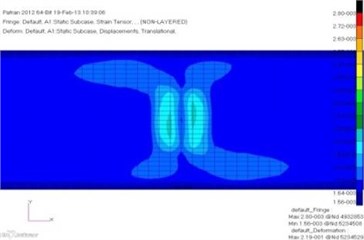
To validate the relationship between local stiffness (local elastic modulus) and crack damage status in the proposed fracture monitoring mechanism above, the strain distribution on the surface of CFRP tensile specimen with different length of crack has been analyzed. Fig. 3 illustrates the strain contour in the crack region on the surface of the specimen (9th layer) with the same depth and different length of cracks.
According to Fig. 3, the strain distribution on the surface of CFRP tensile specimen in the crack region is constantly changing with the increase of the crack length under the same load.
By extracting the strain value of the relevant location in above strain contour, the local elastic modulus value has been analysed. Based on the static analysis, the strain is proportional to the elastic modulus, that is, the equivalent elastic modulus can be obtained from the change of strain value in corresponding position. The local elastic modulus change of the crack region is shown in Fig. 4.
Fig. 2The strain contour of the crack region with 0.6 mm depth and 10 mm length of buried crack
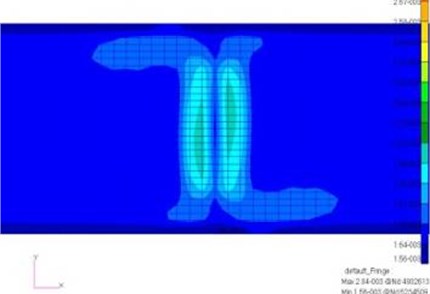
Fig. 3The strain contour in the crack region on surface (9th layer) of specimen with 0.6 mm depth of crack
a) Crack length of 1 mm
b) Crack length of 2 mm
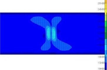
c) Crack length of 5 mm
d) Crack length of 7 mm
Fig. 4The local elastic modulus change of the crack region with different crack lengths
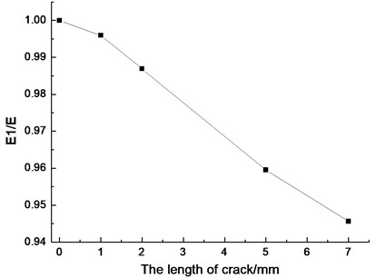
Fig. 5The crack monitoring test of CFRP: a) The form of the test piece, b) The crack monitoring site map
a)

b)
From the above analysis, we can get that the elastic modulus change of CFRP structure is associated with the damage states, that is, with the ongoing stretching, the local elastic modulus nearby the crack damages is decreasing with the increasing of the micro-damage. Thus, by monitoring the change of macro-elastic modulus during the stretching, the damage state of composite in a macro perspective has been obtained, leading to a real-time monitoring to the fracture progress.
4. Fracture-damage monitoring system for CFRP specimen
The monitoring of crack damage of typical CFRP structural components is based on the FBG strain-sensitive characteristic on the surface of composite. By measuring the center wavelength changes of FBGs caused by strain wave response of cracks, the crack status of CFRP in the stretching will be monitored.
The structure form of CFRP components and the FBG-based CFRP crack monitoring system are shown in Fig. 5, which figures that the structure form of CFRP is the typical axial tensile specimen. The type of CFRP, the stacking sequence and the size of specimen are consistent with the parameters of the Finite-element model in section 3.1. The mechanical parameters of the specimens are shown in Table 1.
During the experiment, the incident light produced by the built-in light source of the optical sensing interrogator (Si425) reflects through the FBG probe, and comes into the optical sensing interrogator used to collect the change of the center wavelength of FBG reflected light from the incident end.
5. Fracture monitoring test
5.1. Fracture monitoring test and results
According to the form of test pieces, three FBGs with the center wavelength 1531.123 nm, 1531.103 nm and 1531.085 nm are pasted respectively on the surface of the tensile specimen during the experiment, which is shown in Fig. 5(a). Three FBG probes come into three channels of the optical sensing interrogator and sensors 1, 2, 3 are arranged in the region L1, L2, L3 along the tensile direction, respectively. Using the tensile testing machine, the tensile specimen is stretching with the speed of 0.5 mm/min until the complete rupture.
Fig. 6The fractured CFRP tensile specimen
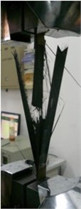
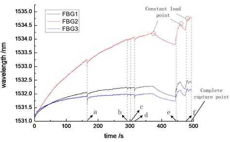
Fig. 7The fracture response curve of CFRP tensile composite specimen, (a, b, c, d, e and f are time points of strain response signal sensed by FBG)
For getting a more accurate internal injuries status, the load was respectively maintained at 373.880 s, 459.436 s and 481.392 s in the stretching process. The fractured CFRP specimen is shown in Fig. 6.
Fig. 8The response curve between load and time from the tensile testing machine
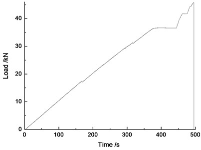
Fig. 7 illustrates the strain response curve of FBGs during the whole stretching process of CFRP composite specimen until the complete rupture. During the experiment, a large breakpoint or a crack-propagation appeared on fibers at 165.428 s, 292.364 s, 301.272 s, 314.184 s, 444.932 s and 479.332 s of the stretching process. At these moments, the strain on the surface of the entire specimen dropped suddenly, and the instantaneous wavelength variable of the sensor near the breakpoint position was slightly larger than others. As the stretch continues, the surface strain of CFRP specimen returned to its original state, that is, the center wavelength of FBG continued to increase. In order to simulate the force condition of the actual structure more accurately, the load was maintained a constant state at 373.880 s, 459.436 s and 481.392 s of the stretching process, respectively. The load-time curve of the entire process obtained by the tensile testing machine is showed in Fig. 8. As there have been severe internal damages in the CFRP composite before the load maintaining, damages such as crack growth, interface debonding, etc. in the CFRP were still ongoing during the load maintaining. When these damages occurred in non-sensor position, the strain of non-sensor position increased. Because the load and the displacement were maintained, the strain of sensor position has decreased, that is, the center wavelength of FBG sensors has reduced. When the load was imposed again with the original speed, the strain increased at a larger rate. The whole stretching process lasted for 493.196 s. Then, the specimen fractured entirely, and all of the FBGs attached on the surface damaged by energy released from fracture.
5.2. Internal damage-determining method based on modulus analysis (The first stage)
In the stretching process, with the continuous increase of the internal damages, the local stiffness (local macro-elastic modulus) of the tensile specimen decreased. Because the strain change in the middle of the tensile specimen was relatively uniform, the FBG2 pasted in the middle position was selected as the signal analysis unit. The monitoring signal before the load maintaing is shown in Fig. 9.
In the data analysis, the whole process from the beginning of the stretching to the first stress relaxation is divided into eight sections: 0-20 s, 20-40 s, 40-60 s, 60-80 s, 80-100 s, 100-120 s, 120-140 s and 140-165.428 s. Meanwhile, the time period from the first stress relaxation to the next stress relaxation is set to 9-11 sections: 174.436-292.344 s, 294.916-301.268 s and 303.808-314.176 s. The divided segments are shown in Fig. 9. The data of each segment is fitted linearly, and the slope of the fitted trend is shown in Fig. 10.
According to the stretching speed and the parameters of specimens, the specimen has already exceeded its elastic range, coming into the plastic deformation after the first 20 s of the stretching process. Fig. 10 shows the slope of the fitted trend, which figures that with the ongoing stretching, some damages such as fracture, crack propagation, etc. appeared gradually in CFRP specimen which was out of the elastic range, leading to the decrease of the macro-elastic modulus (the decrease of the slope of the fitted trend). When the composite material comes into fracture saturation status, the elastic modulus became steady gradually. This state has been lasted until a lot of energy from the fiber bundle fracture was released, that is, the first obvious stress relaxation appeared at 162.004 s. After each stress relaxation, the macro-elastic modulus of the specimen reduced significantly.
Fig. 9The diagram of the tensile fracture response curve of FBG2 and its data segments
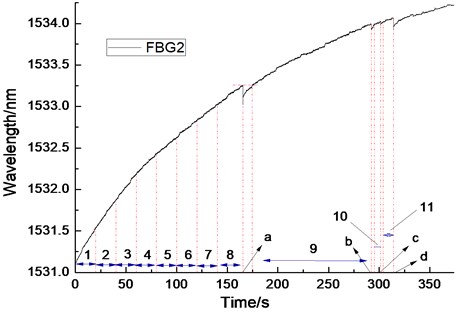
Fig. 10The fitting slope curve of the data segments
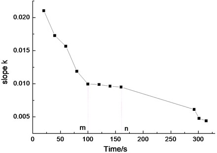
Based on the above analysis and experiments, the reducing trend of macro-elastic modulus of the specimen became steady gradually before significant stress relaxation (the fiber bundle breakage), which is shown as the m-n segment in Fig. 10. Thus, by monitoring the changes of macro-elastic modulus of the specimen, the prediction of fracture saturation status of the specimen can be achieved.
5.3. Internal fracture location-determining based on strain wave response (The second stage)
When the prediction of fracture saturation status of the specimen is realized, the fracture location of CFRP tensile specimen also should be monitored simultaneously. In the stretching process, the fibers with weaker strength fracture first. The strain waves with certain intensity are emitted by breakpoints which are considered as wave sources at the fracture moment, and the strain change near the fiber fracture site is larger than that in the other positions in the instant of fracture, which is shown in Fig. 7.
In the test, breakpoints or large fault-propagations on fibers appeared at 165.428 s, 292.364 s, 301.272 s, 314.184 s, 444.932 s and 479.332 s of the stretching process. At the moment of breakpoints appearance, the surface strain of the entire specimen dropped suddenly, and the variation of FBG wavelength near breakpoints was slightly larger than that of other FBGs. The response variations of the FBG wavelength in different fracture cases are shown in Table 2.
Table 2The response variations of the FBG wavelength in different fracture cases
Break time (s) | 165.428 | 292.364 | 301.272 | 314.184 | 444.932 | 479.332 | |
The maximum variable of FBG wavelength (pm) | FBG1 | 218 | 69 | 51 | 141 | 89 | 49 |
FBG2 | 232 | 70 | 50 | 138 | 84 | 51 | |
FBG3 | 293 | 74 | 50 | 146 | 82 | 50 | |
According to Table 2, the wavelength variation of FBG3 is greater than FBG1 and FBG2 at 165.428s of the stretching, and it is judged that the location of fracture is near FBG3 where is between FBG2 and FBG3. Similarly, the approximate locations of other breakages also can be inferred. The determining results of the fracture locations are in line with the actual break forms showed in Fig. 6.
6. Conclusion and future work
In this paper, the strain sensitivity of FBG has been applied to monitor the fracture status of CFRP composite, and an FBG staged monitoring method based on modulus/strain wave coupling properties designed to monitor tensile fracture state of CFRP has been proposed. The entire process of the tensile fracture monitoring is divided into the following two stages: 1) By monitoring the change of macro-elastic modulus during the stretching, the damage state of CFRP in a macro perspective has been obtained; 2) After the internal damage reached a critical state, by monitoring the strain wave response in different locations induced by stress relaxation, the fracture distribution status of CFRP tensile specimen during the tensile process is obtained. Through the above processes, the proposed staged monitoring method based on modulus/strain wave coupling properties which is simple, accurate and reliable has achieved the prediction of fracture saturation status and the breakage position identification.
Furthermore, we note that the calibration of FBG and the monitoring process might be improved that can make a better application for CFRP structural health monitoring field. Finally it can achieve higher accuracy and meet the requirements for different forms of CFRP structures.
References
-
Dvorak G. J. Composite materials: Inelastic behavior, damage, fatigue and fracture. International Journal of Solids and Structures, Vol. 37, Issue 1-2, 2000, p. 155-170.
-
Post N. L., Case S. W., Lesko J. J. Modeling the variable amplitude fatigue of composite materials: A review and evaluation of the state of the art for spectrum loading. International Journal of Fatigue, Vol. 30, Issue 12, 2008, p. 2064-2086.
-
Zhu S., Mizuno M., Kagawa Y., Mutoh Y. Monotonic tension, fatigue and creep behavior of SiC-fiber-reinforced SiC-matrix composites: a review. Composites Science and Technology, Vol. 59, Issue 6, 1999, p. 833-851.
-
Crouch R. D., Clay S. B., Oskay C. Experimental and computational investigation of progressive damage accumulation in CFRP composites. Composites Part B-Engineering, Vol. 48, 2013, p. 59-67.
-
Ullah H., Harland A. R., Silberschmidt V. V. Damage and fracture in carbon fabric reinforced composites under impact bending. Composite Structures, Vol. 101, 2013, p. 144-156.
-
Withers P. J., Bennett J., Hung Y.-C., Preuss M. Crack opening displacements during fatigue crack growth in Ti-SiC fiber metal matrix composites by X-ray tomography. Materials Science and Technology, Vol. 22, Issue 9, 2006, p. 1052-1058.
-
Goidescu C. Welemane H., Garnier C., Fazzini M., Brault R., Peronnet E., Mistou S. Damage investigation in CFRP composites using full-field measurement techniques: Combination of digital image stereo-correlation, infrared thermography and X-ray tomography. Composites Part B-Engineering, Vol. 48, 2013, p. 95-105.
-
Vikram K. Kinra, Atul S. Ganpatye, Konstantin Maslov Ultrasonic ply-by-ply detection of matrix cracks in laminated composites. Journal of Nondestructive Evaluation, Vol. 25, Issue 1, 2006, p. 39-51.
-
Shiino M. Y., Faria M. C. M., Botelho E. C., de Oliveira P. C. Assessment of cumulative damage by using ultrasonic c-scan on carbon fiber/epoxy composites under thermal cycling. Materials Research-Ibero-American Journal of Materials, Vol. 15, Issue 4, 2012, p. 495-499.
-
Chukwujekwu A. Okafor, Navdeep Singh, Navrag Singh Acoustic emission detection and prediction of fatigue crack propagation in composite patch repairs using neural networks. AIP Conference Proceedings, Vol. 894, 2007, p. 1532-1539.
-
Andrea Bernasconi, Michele Carboni, Lorenzo Comolli Monitoring of fatigue crack growth in composite adhesively bonded joints using fiber Bragg gratings. Procedia Engineering, Vol. 10, 2011, p. 207-212.
-
Keith A. Schweikhard, Lance W. Richards, John Theisen Flight demonstration of X-33 vehicle health management system components on the F/A-18 systems research aircraft NASA/TM-2001-209037. Dryden Flight Research Center, 2001.
-
Hunt S. R., Hebden I. G. Validation of the Eurofighter Typhoon structural health and usage monitoring system. Smart Materials and Structures, Vol. 10, Issue 3, 2001, p. 497-503.
-
Yung Bin Lin, TzuKang Lin, Chun-Chung Chen, Jen Chang Chiu, Kuo Chun Chang Online health monitoring and safety evaluation of the relocation of a research reactor using fiber Bragg grating sensors. Smart Materials and Structures, Vol. 15, Issue 5, 2006, p. 1421-1428.
-
Propst A., Peters K., Zikry M. A., Schultz S., Kunzler W., Zhu Z., Wirthlin M., Selfridge R. Assessment of damage in composite laminates through dynamic, full-spectral interrogation of fiber Bragg grating sensors. Smart Materials and Structures, Vol. 19, Issue 1, 2010, p. 015016.
-
Ettore Barbieri, Michele Meo A meshless cohesive segments method for crack initiation and propagation in composites. Applied Composite Materials, Vol. 18, Issue 1, 2011, p. 45-63.
-
Andersons J., Tarasovs S. Finite fracture mechanics analysis of crack onset at a stress concentration in a UD glass/epoxy composite in off-axis tension. Composites Science and Technology, Vol. 70, Issue 9, 2010, p. 1380-1385.
-
Supti Sadhukhan, Tapati Dutta, Sujata Tarafdar Crack formation in composites through a spring model. Physica A, Vol. 390, Issue 4, 2011, p. 731-740.
-
Myriounis D. P., Kordatos E. Z., Hasan S. T., Matikas T. E. Crack-tip stress field and fatigue crack growth monitoring using infrared lock-in thermography in A359/SiCp composites. Strain, Vol. 47, Issue 1, 2011, p. e619-e627.
-
Hu H., Lee C. H., Wu C. B., Lu W. J. Detection of matrix cracks in composite laminates by using the modal strain energy method. Mechanics of Composite Materials, Vol. 46, Issue 2, 2010, p. 117-132.
-
Maimí P., Camanho P. P., Mayugo J. A., Turon A. Matrix cracking and delamination in laminated composites. Part II: Evolution of crack density and delamination. Mechanics of Materials, Vol. 43, Issue 4, 2011, p. 194-211.
-
Jacob Aboudi, Michael Ryvkin Dynamic stresses created by the sudden appearance of a transverse crack in periodically layered composites. International Journal of Engineering Science, Vol. 49, Issue 7, 2011, p. 694-710.
-
Kumar M. S., Raghavendra K., Venkataswamy M. A., Ramachandra H. V. Fractographic analysis of tensile failures of aerospace grade composites. Materials Research-Ibero-American Journal of Materials, Vol. 15, Issue 6, 2012, p. 990-997.
-
Perez Grassi A., Muller M. S., Bernardini A., El-Khozondar H. J., Koch A. W. Method for strain tensor reconstruction with embedded fiber Bragg grating sensors. Smart Materials and Structures, Vol. 20, Issue 10, 2011, p. 105031.
-
Karalekas D., Cugnoni J., Botsis J. Monitoring of process induced strains in a single fibre composite using FBG sensor: A methodological study. Composites. Part A, Vol. 39, Issue 7, 2008, p. 1118-1127.
About this article
This work is supported by the National Natural Science Foundation of China (51308108, 51275239), the Postdoctoral Science Foundation of China (2013M540407), the General and Special Program of the Postdoctoral Science Foundation of China (2014T70457), the Postdoctoral Research Funding Scheme of Jiangsu Province (1301026B), the Natural Science Foundation of Jiangsu (BK2010397) and the Postdoctoral Research Funds of Southeast University.
