Abstract
The nanosatellites of the CubeSat standard (10×10×10 cm and with mass 1-10 kg) was designed to reduce cost and development time and to maximize science return. However, the small size of the spacecraft imposes substantial mass, volume, and power constraints. The challenge remains to be the miniaturization of the various robots for the manipulation of functional objects, such as cameras, laser sources, mirrors and other used in nanosatellites. Therefore in particular, precision positioning of the manipulated object is important task for robots used in nanosatellites as well. In this paper authors present the design of robot driven by the piezoelectric actuators. Investigations of the robot are presented and they prove ability to improve the accuracy of the movement for the robot arm using two bending bimorph type piezoelectric actuators and 3DOF rotary piezoelectric motor.
1. Introduction
As a result of budget reduction and advances in microelectronics, nanosatellites weighing 1-10 kg have been actively developed. Their mission is wide-ranging: remote sensing, communications, science, technology demonstration and military. Nanosatellites in generally are measured in dimensions of 10 cm×10 cm×10 cm. [1] Seeking to reach the aims of the missions there are used special equipment in the nanosatellites. One of such equipment is piezoelectric robotic arm that is usually responsible for manipulated objects, such as cameras, laser beams, mirrors, optical elements and other.
Piezoelectric bending actuators are widely investigated. They are used for many different applications, such as precision movement mechatronic systems, optical devices, medicine equipment, space technologies and other [2-4]. Precision positioning of the manipulated object is important task for robots used in nanosatellites. Very exhaustive review of robotic micro- and nano-manipulation can be found in [5, 6, 7, 8].
Piezoelectric effect generates small deformations of piezoelectric bimorph and that is the reason why deflection angle of actuator reaches only 0.01-0.5○ [9]. Recent advances in smart materials have enabled to produce actuators for generation high enough force and dynamic/static deflection in millimetre-scale mechanical structures [10, 11].
In this paper authors present the design of micro robotic arm using two bending bimorph type piezoelectric actuators and 3DOF rotary piezoelectric motor that enables the robot arm to rotate 360 degrees around the axis and 170 degrees around and axis. Robot consists of piezoelectric cylinder, ferromagnetic sphere, two cantilever piezoelectric bending actuators [12, 13] and manipulated objet (camera, laser source or other). This actuator that consists of two bending bimorphs improves the accuracy of the positioning angles for robotic arm. Such piezoelectric bending actuator can be characterized as low price and simple design.
2. Design of piezoelectric robot for nanosatellites
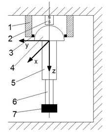
Connecting the electrodes of the piezoelectric cylinder 1 to the electrical voltage according to electrode configuration shown in Fig. 1(b), a travelling or standing waves on the contacting elements 3 is created. Because of this reason ferromagnetic sphere (rotor) 4 starts the rotational movement around axis , or (Fig. 1(a)). The sphere-shape rotor 4 of the robot arm can rotate 360 degrees around the axis and 170 degrees around and axis. For precision positioning of the manipulated object the arm of robot is fabricated of two piezoelectric cantilevers bending actuators bonded together in series and is fixed on the surface of the sphere 4. First piezoelectric cantilever bimorph 5 creates bending movement around axis and second piezoelectric bimorph 6 around axis (Fig. 1(a)).
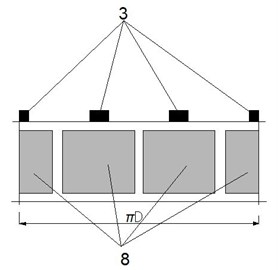
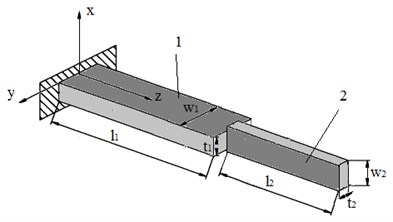
Fig. 1Piezoelectric robot: a) scheme of the robot; b) piezoelectric cylinder electrodes configuration, here: 1 – piezoelectric cylinder, 2 – permanent magnet, 3 – friction contact elements, 4 – ferromagnetic sphere-rotor, 5 – first piezoelectric bimorph, 6 – second piezoelectric bimorph, 7 – manipulated object, 8 – configuration of the piezoelectric cylinder electrodes; c) geometrical parameters of 2D actuator, here: 1 – first piezoelectric bimorph, 2 – second piezoelectric bimorph, l1 – length of first bimorph, l2 – length of second bimorph, w1 – width of first bimorph, w2 – width of second bimorph, t1 – thickness of first bimorph, t2 – thickness of second bimorph
a)
b)
c)
For the 2D bending actuator (Fig. 1(c)) two piezoelectric bimorphs were used. Dimensions of the actuators are presented in Fig. 2: – length of first bimorph (50 mm), – length of second bimorph (40 mm), – width of first bimorph (7.8 mm), – width of second bimorph (2 mm), – thickness of first bimorph (1.8 mm), – thickness of second bimorph (0.8 mm).
3. Modelling of bimorph actuators
A harmonic analysis of 2D piezoelectric actuator (Fig. 2) was made by using finite element method (FEM). FEM was used to perform numerical modelling of the actuator. It was used to carry out modal frequency and harmonic response analysis and to calculate displacements of the free tip movements of bimorph-type cantilever. Driving force of the piezoelectric actuator is obtained from piezoelectric ceramic’s plate. FE discretization of this element usually consists of a few layers of finite elements. Therefore nodes coupled with electrode layers have known potential values in advance and nodal potential of the remaining elements are calculated during the analysis. Dynamic equation of piezoelectric actuator is derived from the principle of minimum potential energy by means of variational functionals and in this case can be expressed as follows [14]:
where , , , , are matrices of mass, stiffness, electro elasticity, capacity, damping respectively; , , are vectors of nodes displacements, structural mechanical forces and charge; , are accordingly vectors of nodal electrical potentials known in advance and calculated during numerical simulation.
Natural frequencies and modal shapes of the actuator are derived from the modal solution of the piezoelectric system [14, 15]:
where is modified stiffness matrix and it depends on nodal potential values of the piezoelectric elements.
Harmonic response analysis of piezoelectric actuator is carried out applying sinusoidal varying voltage on electrodes of the piezoelectric elements. Structural mechanical loads are not used in our case, so . Equivalent mechanical forces are obtained, because of inverse piezoefect and can be calculated as follows [15]:
here , where is vector of voltage amplitudes, applied on the nodes coupled with electrodes.
Results of structural displacements of the piezoelectric actuator obtained from harmonic response analysis are used for determining the displacement of the tip movement.
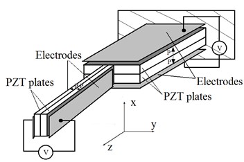
FEM software ANSYS v.13 was used to perform numerical modelling of the two bimorph actuators. The aim of the modelling was to perform modal-frequency, deformations and harmonic response analysis of the actuators. Finite element model was made of SOLID5 and SOLID45 finite elements [16, 17]. It was assumed that polarization direction of the piezoelectric ceramic is constant within the finite element pale and is organized along axis for the first bimorph and along axis for the second bimorph (Fig. 2(a)). The material properties of the finite element models are given in Table 1. One end of the bimorph actuator was clamped so all mechanical degree of freedom of corresponding nodes was set to zero. The electrodes layers on the top and bottom of the actuator were not considered in the FEM model. Electrodes were created by grouping surface nodes of the FEM model and harmonic voltage of excitation 12 V were applied.
Table 1Parameters of piezoelectric material
Material | PZT-5H | |
Piezoelectric constants, (m/V×10-12) | –265 | |
585 | ||
Coupling factor, | 0.68 | |
Density , kg/cm3 | 7550 | |
Dielectric constant | 3400 | |
Mechanical | 65 | |
Young’s modulus , GPa | 60 | |
Relative dielectric constant | 3200 | |
Fig. 2Investigated piezoelectric actuator: a) structure of 2D actuator used in FEM, b) FEM for numerical modelling
a)
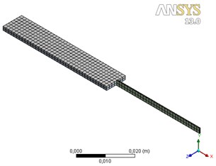
b)
Fig. 3Directional deformations of 2D actuator: a) first piezoelectric bimorph in x direction, b) second piezoelectric bimorph in y direction
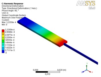
a)
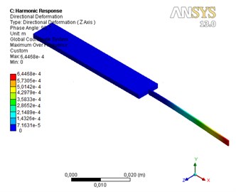
b)
The modal shapes and the resonant frequencies of the actuators were calculated and harmonic response analysis was performed. The first bending mode out of plane is the object of interest and natural frequency of this mode was found at 216 Hz for first actuator and at 234 Hz for the second actuator (Fig. 4(a)).
Peaks in the graphs (Fig. 4(a)) indicate the resonant vibrations at first bending mode. Resonance amplitudes are 334 µm and 645 µm accordingly for first and second actuator.
Fig. 4Numerical modelling: a) frequency response of piezoelectric actuators, b) amplitude of the tip deflection for actuators as a function of applied electric voltage at low frequency. Here 1 – first piezoelectric bimorph, 2 – second piezoelectric bimorph
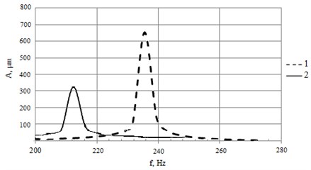
a)
b)
4. Experimental investigations
The prototype of 2D piezoelectric bending actuator (Fig. 4(b)) was made for experimental investigation of its dynamic and precision positioning characteristics. Two commercial piezoelectric bimorphs were used: 1 – of type CMBP09 (Noliac A/S, Denmark) and 2 – of type 2 (Johnson Matthey Catalysts GmbH, Germany). Experimental set up is presented in Fig. 4(a). The total response of the actuator consists of two components: a fast inertial response that influences the dynamics in the short travel and high frequency range, and a hysteretic response due to dipole domain switching in piezoelectric materials, which resembles a nonlinear relaxation process.
Therefore during experiments there were investigated two characteristics of piezoelectric actuator: frequency responses and hysteresis of displacement. Measurements were made on the tip of second piezoelectric bimorph, when voltage of 12 Vpp of harmonic signal is applied. The aim of these experiments was to investigate dynamics and precision positioning of the manipulated object. Fast response is one of characteristic features of piezoelectric actuators. A rapid drive voltage changes the results in a rapid position change. This property is especially welcome in dynamic applications of manipulator such as scanning, image stabilization, vibration cancellation systems, etc. Piezoelectric bending bimorph can reach its nominal displacement in approximately 1/3 of the period of the resonant frequency with significant overshoot [18]. If the voltage rises fast enough to excite a resonant oscillation in the piezoelectric actuator the ringing and overshoot will occur [19]. For the fastest settling, switched operation is not the best solution. If the input signal rise time is limited to a period of the resonant frequency, the overshoot can be reduced significantly. Pre-shaped input signals (optimized for minimum resonance excitation) reduce the time to reach a stable position.
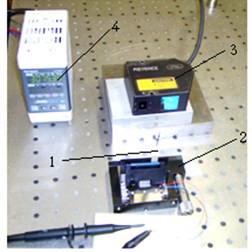
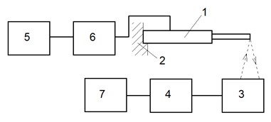
Experimental set up is shown in Fig. 5. It consists of: 1 – investigated 2D piezoelectric bending actuator, 2 – holder of piezoelectric actuator, 3 – laser displacement sensor LK-G82, 4 – laser sensor controller LK-G3001PV, 5 – signal generator Agilent 33220A, 6 – voltage amplifier EPA-104, 7 – PC with analog-digital converter.
Fig. 5Experimental investigation: a) setup and b) structural scheme of experimental setup
a)
b)
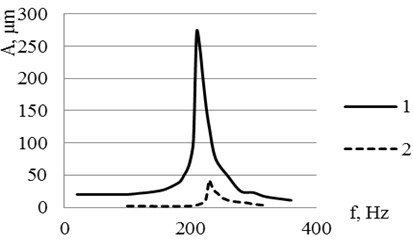
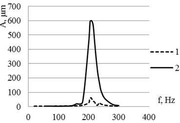
Fig. 6Frequency response for the piezoelectric 2D bending actuator used in experiments: a) frequency responses of the actuator tip when second bimorph is exited: 1 – in y direction, 2 – in x direction; b) frequency responses of the actuator tip when first bimorph is exited: 1 – in x direction, 2 – in y direction
a)
b)
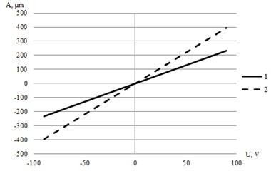
From amplitude-frequency curves it can be seen that investigated actuator reaches its resonance at frequency 210 Hz (amplitude – 275 µm), when second bimorph is exited (Fig. 6(a)). In this case movement of the tip is generated in y direction. During vibrating process of first bender, second bimorph gets movement as well. When first bender gets vibrations, the tip of second bender resonates at frequency of 230 Hz and reaches amplitudes of 600 µm in direction. For the precision positioning a piezoelectric bending bimorph can reach its nominal displacement in approximately 1/3 of the period of the resonant frequency. So operating frequency range of investigated actuator for precision positioning in y direction is 0-70 Hz, and in direction 0-80 Hz.
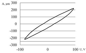
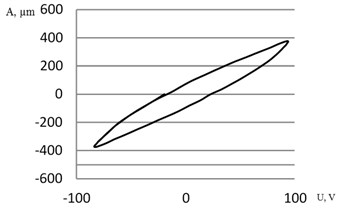
During experimental investigations of generated displacements the hysteresis of approximately 25 % for the tip of piezoelectric actuator in -plane is measured (20 Hz). Thus the control system with feedback for precision positioning of manipulated object must be applied.
Fig. 7Flexural deflection of the actuator’s tip under a sinusoidal input voltage and frequency of 20 Hz: a) hysteresis of the first bimorph; b) hysteresis of the second bimorph
a)
b)
5. Conclusions
A piezoelectric-driven 2D scanning actuator using two piezoelectric bimorph cantilevers bonded in series and placed in perpendicular direction has successfully been designed, fabricated and tested. Two bending modes of scanning operation have been investigated. By applying 12 Vpp, the tip of actuator can achieve horizontal and vertical resonant vibrational amplitudes of 275 µm and 600 µm in the bending mode. During experimental investigation there was the hysteresis of approximately 25 % for the piezoelectric actuator in -plane measured. For precision poisoning of manipulated object control system with feedback must be applied. Development and implementation of model-based manipulator control systems are currently ongoing research.
References
-
Crook M. R. NPS cubesat launcher design, process and requirements. Naval Postgraduate School.
-
Shaffer J. J., Fried D. L. Bender-bimorph scanner analysis. Applied Optics, Vol. 9, Issue 4, 1970, p. 933-937.
-
Muralt P., Pohl D. W., Denk W. Wide-range, low-operating-voltage, bimorph STM: applications as potentiometer. Journal of Research and Development, Vol. 30, Issue 5, 1986, p. 443-450.
-
Lanyi S., Ozvold M. Improved wide-range bimorph scanners. Ultramicroscopy, 1992, p. 1664-1667.
-
Fukuda T., Arai F., Dong L. Assembly of nanodevices with carbon nanotubes through nanorobotic manipulations. Proc. IEEE, Vol. 91, Issue 11, 2003, p. 1803-1818.
-
Xi N., Li W. Recent development in nanoscale manipulation and assembly. Transactions on Automation Science and Engineering, Vol. 3, Issue 3, 2006, p. 194-198.
-
Smits J. G., Choi W. The constituent equations of piezoelectric heterogeneous bimorphs. IEEE Transactions on Ultrasonics Ferroelectrics and Frequency Control, Vol. 38, Issue 3, 1991, p. 256 270.
-
Ansari M. Z., Cho C. Deflection, frequency, and stress characteristics of rectangular, triangular, and step profile microcantilevers for biosensors. Sensors, 2009, p. 6046-6057.
-
Kelly Lee J. Piezoelectric bimorph optical beam scanners: anglysis and construction. Applied Optics, Vol. 18, Issue 4, 1979, p. 454-459.
-
Ohtuka Y., Nishikawa H., Koumura T., Hattori T. 2-Dimensional optical scanner applying a torsional resonator with 2 degree of freedom. Proceedings of the IEEE Micro Electro Mechanical Systems (MEMS), Amsterdam, Netherlands, 1995, p. 306-309.
-
Ikeda M., Totani H., Akiba A., Goto H., Matsumoto M., Yada T. PZT thin film actuator driven micro optical scanning sensor by 3D integration of optical and mechanical devices. Proceedings of the IEEE Micro Electro Mechanical Systems (MEMS), Orlando, USA, 1999, p. 435-440.
-
Yorinaga M., Makino D., Kawaguchi K., Naito M. A piezoelectric fan using PZT ceramics. Japanese Journal of Applied Physics, Vol. 24, 1985, p. 203-205.
-
Yoo J. H., Hong J. I., Cao W. Piezoelectric ceramic bimorph coupled to thin film metal plate as cooling fan for electronic devices. Sensors and Actuators A, Vol. 79, 2000, p. 8-12.
-
Frangi A., Corigliano A., Binci M., Faure P. Finite element modelling of a rotating piezoelectric ultrasonic motor. Ultrasonics, Vol. 43, Issue 9, 2005, p. 747-755.
-
Sitti M., Campolo D., Yan J., Fearing R. Development of PZT and PZN-PT based unimorph actuators for micromechanical flapping mechanisms constant magnet motors. USA, 2001.
-
Frangi A., Corigliano A., Binci M., Faure P. Finite element modelling of a rotating piezoelectric ultrasonic motor. Ultrasonics, Vol. 43, Issue 9, 2005, p. 747-755.
-
Sitti M., Campolo D., Yan J., Fearing R. Development of PZT and PZN-PT Based Unimorph Actuators for Micromechanical Flapping Mechanisms Constant magnet motors. USA, 2001.
-
Uchino K. Piezoelectric Actuators and Ultrasonic Motors. Springer, 1997, p. 336.
-
Barrett R. C., Quate C. F. Optical scancorrection system applied to atomic force microscopy. Review of Scientific Instruments, Vol. 62, Issue 6, 1991, p. 1393-1399.
About this article
Postdoctoral fellowship is being funded by European Union Structural Funds project “Postdoctoral Fellowship Implementation in Lithuania” within the framework of the Measure for Enhancing Mobility of Scholars and Other Researchers and the Promotion of Student Research (VP1-3.1-ŠMM-01) of the Program of Human Resources Development Action Plan.
