Abstract
For energy-dissipation devices, identification of the physical behavior is a more difficult task than their design. This study develops an identification technique that is useful for the acquirement of the dynamic characteristics of buildings with symmetric ductile braces (SDBs) which exhibit bilinear behavior. The considered system is a linear multi-story building with SDBs regarded as a bilinear hysteretic model. The complex multi-degree-of-freedom problem was solved in the pseudo-single-degree-of-freedom domain, and the dynamic parameters of primary building as well as the SDBs are sequentially identified from top to bottom stories based on the input and output responses of floors. To simplify the nonlinear problem, a backbone curve, where the multi-values restoring force is transformed into a single-valued function, is applied to characterize the hysteretic model. A numerical study demonstrates that the proposed identification technique was able to extract the physical parameters of the primary building and the SDBs individually from the floor responses. It may be applied to the health monitoring of buildings protected by nonlinear energy-dissipation devices.
1. Introduction
Conventional buildings rely on self-ability to dissipate the vibration energy from earthquakes. In the past two decades, numerous scholars and engineers worldwide have devoted their attention to methods that help to reduce damage to structures during strong earthquakes. Specifically, a number of extant studies have focused on base-isolated systems that directly reduce base input energy; other scholars have used energy dissipation systems, which appropriately integrate energy dissipation devices with structures. Energy dissipation systems convert the inter-story displacement or relative velocity of a structure into the mechanical force that drives energy dissipation devices, thus absorbing seismic energy propagating in structures. Energy dissipation systems can be categorized into two types. The first type employs the plastic deformation of metal materials to absorb energy from hysteretic loops produced during cyclic loading. The second type of energy dissipation system utilizes the relative motion within dampers to generate resistance by driving the flows of materials that consist of fluids or quasi-solid substances or by generating a vibration-resistant force from the materials’ viscosity, such as in viscous-fluid dampers [1]. Wang and Chang Chien [2] applied the nonlinear behavior of Pre-bent strips (PBSs) under dynamic loading and proposed a buckling-structured damping device. This study of component analysis indicated that a PBS under cyclic loading displays an asymmetric mechanical behavior. Chang Chien [3] further modified the PBS into a ductile brace, and employed ductile braces with a symmetric setting to explore their vibration resistance. Compared to Buckling-restrained braces (BRBs), which do not tend to yield in response to seismic forces, this research results showed that symmetric ductile braces (SDBs) allowed buckling and deformation, which, when slightly deformed, produced yield and subsequently provided hysteretic loops. Thus, SDBs are able to dissipate seismic energy early in an earthquake. Furthermore, according to his study, SDBs comprising PBSs display a symmetric hysteretic behavior similar to bilinear hysteresis.
In this study, a pseudo-single-degree-of-freedom system identification procedure is developed to investigate the dynamic characteristics of energy-dissipated buildings equipped with symmetric ductile braces (SDBs). The primary structure is assumed to be linear on account of substantial reduction of seismic forces due to the installation of SDBs for which a bilinear hysteretic model is considered. The hysteretic model is in turn characterized by a backbone curve by which the multi-valued restoring force is transformed into a single-valued function. With the introduction of backbone curves, the system identification analysis of inelastic structures is simplified to a large extent. The proposed algorithm extracts individually the physical parameters of each primary structure and each energy-dissipation device that are considered useful information in the structural health monitoring. A numerical example is conducted to demonstrate the feasibility of using the proposed technique for physical parameter identification of partially inelastic energy-dissipated buildings.
2. Motion equation
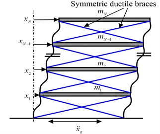
Consider a -story energy-dissipated building structure with SDBs, as shown in Fig. 1. The primary structure is assumed to be linear on account of the reduction in seismic forces due to the SDBs. Accordingly, the equations of motion of the energy-dissipated structure can be expressed as:
where is the displacement of the th floor relative to ground; is the mass of the th floor; and represent the damping coefficient and stiffness coefficient of the th primary structure, respectively; and is the coefficient of damping, and refers to the hysteretic restoring force of the th SDBs to be defined later; is the horizontal ground acceleration.
Fig. 1Energy-dissipated building
3. Pseudo-single-degree-of-freedom system
Dividing both sides of Eq. (1) by and subtracting from the quotient forms a pseudo-SDOF motion equation of the th floor as:
Similarly, (2) and (3) were rewritten as pseudo-SDOF motion equations for floors to as:
4. Bilinear hysteretic model
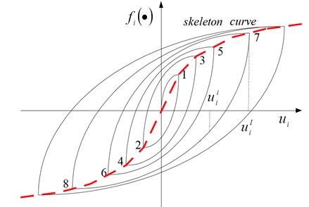
The restoring force, , is path-dependent. In general, all hysteresis loops are smooth except at the turning points. They can usually be characterized by skeleton curves (or backbone curves). Under steady-state cyclic loadings, the hysteretic behavior of these models can be properly described by Masing criterion [4], which assumes that the unloading portion of the hysteresis loop follows the same skeleton curve as the reloading but with the scale expanded by a factor of two and the origin translated to the point of force reversal [4, 5], as shown in Fig. 2. The restoring force of the th SDBs after the first unloading is discretized and expressed as:
in which is the instant of most recent loading reversal; is the th floor displacement at instant with , and is a function representing the skeleton curve which is assumed to be bilinear in this study characterized by three line segments with slopes of or as:
where denotes the yielding displacement and is the characteristic strength.
When Eq. (7) is substituted into Eq. (4), the governing equation of the th floor at instant becomes:
Fig. 2Hysteresis loops based on skeleton loading curve
At instant , the above equation reduces to:
Substituting Eq. (10) for into Eq. (9), one gets:
Defining:
in Eq. (12) and substituting it into Eq. (11), the governing equation can be rewritten as:
Substituting Eq. (8) into Eq. (13), and denoting the right-hand side of Eq. (13) as , the governing equation can be rewritten as:
Eqs. (14)-(16) are used to identify the parameters of the th floor of energy-dissipated building.
5. Physical identification
Identification of the system parameters can be conducted once the dynamic responses of the structure subjected to the input excitation are available [6]. Based on an output-error concept [7], the system parameters are obtained by minimizing the discrepancy between the recorded and predicted responses of the system. The system parameters so evaluated are considered optimal.
Using the first set of data for and Eq. (14), the partial measure-of-fit can be defined as:
The values of and are obtained by simultaneously solving:
Similarly, application of the second data set for and Eq. (15) produces another partial measure-of-fit as:
extremization of Eq. (19) with respect to the unknowns yields:
from which the values of , and are obtained. Finally, application of the third data set for and Eq. (16), the third partial measure-of-fit is defined as:
Minimization of with respect to , and respectively, i.e. solving the system equations of:
However, to ensure satisfaction of a prescribed criterion, say, the global measure-of-fit defined as:
The set of and that gives the minimum global measure-of-fit is regarded as the solution. Moreover, parameters identified from different set of data are somewhat different. In such a circumstance, the average value of all is adopted. Similarly, physical parameters of floors to could be obtained using Eqs. (5) and (6) and the aforementioned procedures.
Moreover, to assess the overall accuracy of the identification process, an error index is defined as:
where is the recorded or measured acceleration response of the th floor and the corresponding theoretical or predicted response. The latter is calculated from the identified system parameters with the recorded input excitation.
6. Numerical example
As an effort to verify the proposed methodology for system identification of buildings, a numerical example is considered using a 3-story energy-dissipated building with SDBs. The system parameters considered in this study include: (1) and for the primary structure; (2) and for the SDBs.
Dynamic responses of the energy-dissipated building under the N-S component of the 1940 El Centro earthquake are calculated using Newmark’s linear acceleration method with a time-step of 0.02 sec. The acceleration responses contaminated with an artificial white noise signal of 5 % noise-to-signal ratio are considered in the system identification analysis to simulate the measured data in a more realistic manner.
Fig. 3 presents the nonlinear restoring force of the 3rd SDBs with a yielding displacement of 0.199 cm and a ductility ratio of 2.49. The force-displacement relationship of the story shear at the 3rd primary structure is almost linear, as illustrated in Fig. 4.
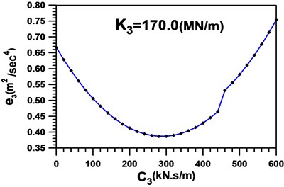
In the first cycle of the identification process, the initial value of is arbitrarily set to be zero. The global measure-of-fit with respect to is presented in Fig. 5 from which the least squares estimate of is shown to be . The minimization process is then proceeded further to find and other system parameters by keeping at this value. The optimal estimate of reads , as illustrated in Fig. 6. Meanwhile, the parameteric values of SDBs are identified as and , respectively.
Fig. 3Nonlinear restoring force of the 3rd symmetric ductile braces
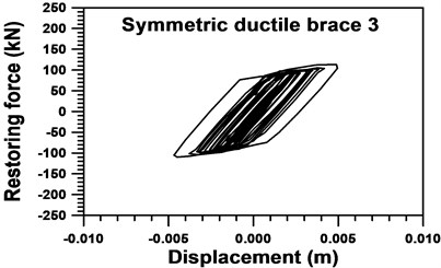
Fig. 4Restoring force and displacement of the 3rd primary structure
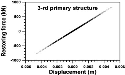
Fig. 5Global measure-of-fit in the first cycle setting C3=0 kN s/m
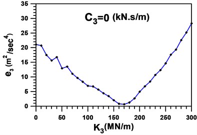
Fig. 6Global measure-of-fit in the first cycle setting K3=170 MN/m
The second iterative cycle is next proceeded by considering the initial value of as derived from the previous cycle. Minimizing the global measure-of-fit, we have , as shown in Fig. 7. Table 1 summarizes the system parameters of the 3rd SDBs and 3rd primary structure identified in three iterative cycles, while all the parameters used to describe the 1st SDBs, 2nd SDBs, and 1st and 2nd primary structures are further listed in Table 2 and Table 3, respectively.
Table 1Identified parameters of the 3rd SDBs and 3rd primary structure
Number of cycle | ||||||
1 | 198.0 | 75.274 | 5.064 | 42.170 | 280.0 | 170.00 |
2 | 194.0 | 75.274 | 8.065 | 45.170 | 284.0 | 167.00 |
3 | 194.0 | 75.274 | 7.965 | 45.070 | 284.0 | 167.10 |
True value | 156.0 | 74.556 | 6.867 | 44.145 | 321.0 | 168.06 |
E. I. | 0.3622 | |||||
Table 2Identified parameters of the 2-nd SDBs and 2-nd primary structure
Number of cycle | ||||||
1 | 227.0 | 72.141 | 15.392 | 51.613 | 290.0 | 160.00 |
2 | 228.0 | 72.141 | 8.392 | 44.613 | 289.0 | 167.00 |
3 | 228.0 | 72.141 | 8.392 | 44.613 | 289.0 | 167.00 |
True value | 156.0 | 74.556 | 6.867 | 44.145 | 321.0 | 168.06 |
E. I. | 0.3756 | |||||
Table 3Identified parameters of the 1-st SDBs and 1-st primary structure
Number of cycle | ||||||
1 | 145.0 | 75.248 | 4.940 | 43.096 | 300.0 | 170.00 |
2 | 145.0 | 75.248 | 4.940 | 43.096 | 300.0 | 170.00 |
3 | 140.0 | 75.247 | 6.040 | 44.196 | 305.0 | 168.90 |
True value | 156.0 | 74.556 | 6.867 | 44.145 | 321.0 | 168.06 |
E. I. | 0.4462 | |||||
Numerical results in this example suggest that three iterative cycles of identification are enough for sufficient accuracy. In addition, the skeleton curve estimated from the identified parameters of the 3rd SDBs using the Masing criterion is illustrated in Fig. 8. Comparisons of acceleration and displacement of the 3rd floor and the 1st floor are shown from Figs. 9-12, respectively. Satisfactory agreement between the identified and measured responses has been observed indicating adequacy of the proposed identification scheme for partially inelastic dynamic systems.
It is noted that by the proposed method, measurement of ground acceleration and full-state response data including acceleration, velocity and displacement of all degrees of freedom is required. As in most occasions, only the acceleration responses are measured. In this case, the responses of velocity and displacement need to be integrated from the acceleration records with baseline correction. This may inevitably introduce error to the physical parameters identified.
Fig. 7Global measure-of-fit in the second cycle setting C3=280 kN s/m
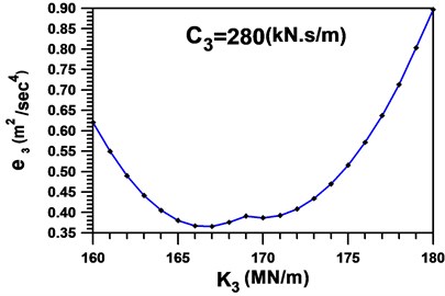
Fig. 8Identified skeleton curve of the 3rd symmetric ductile braces
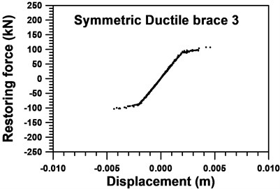
Fig. 9Comparison between identified and measured accelerations of floor 3
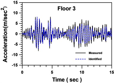
Fig. 10Comparison between identified and measured displacements of floor 3
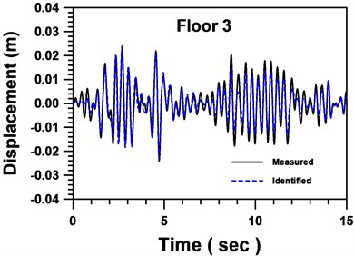
Fig. 11Comparison between identified and measured accelerations of floor 1
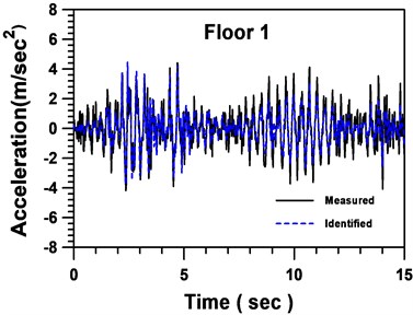
Fig. 12Comparison between identified and measured displacements of floor 1

7. Conclusions
For a structure protected by energy-dissipation devices with nonlinear behavior, it is needed to evaluate the damage of the devices after an earthquake so as to take an immediate action to repair or replace them. This study developed an identification technique for this purpose. A nonlinear system of a multi-story building with multiple SDBs was considered in this paper. A bilinear skeleton curve was used to characterize the behavior of SDBs so that the computational effort is reduced. The identification procedure is sequentially preceded from the top to the bottom stories based on the floor responses.
The proposed procedure was verified via a numerical study which a 3-story building with SDBs in each story is assumed. The stiffness and damping coefficients of the building as well as the physical parameters representing the nonlinear characteristics of the SDBs were obtained in three iterative cycles, even though a noise with 5 % noise-to-signal ratio is contained in the floor responses. The results show that this methodology could be applied to health monitoring of passively controlled systems using devices whose dynamic behavior can be represented with some form of skeleton curve. The proposed identification technique can further be extended to solve systems with high nonlinearity.
References
-
Soong T. T.,Dargush G. F. Passive energy dissipation systems in structural engineering. John Wiley and Sons Inc., New York, 1997.
-
Wang Y. P.,Chang Chien C. S. A study on using pre-bent steel strips as seismic energy-dissipative devices. Earthquake Engineering and Structural Dynamic, Vol. 38, 2009, p. 1009-1026.
-
Chang Chien C. S. An experimental study on displacement-dependent seismic dampers in buckling and friction mechanisms. Ph. D. Dissertation, National Chiao Tung University, Hsinchu, Taiwan, 2008.
-
Jenning P. C. Earthquake response of a yielding structure. Journal of Engineering Mechanics, ASCE, Vol. 91, 1965, p. 41-68.
-
Huang M. C., Wang Y. P., Chang J. R., Chen Y. H. Physical-parameter identification of base-isolated buildings using backbone curves. Journal of Structural Engineering, ASCE, Vol. 135, Issue 9, 2009, p. 1107-1114.
-
Varghese C. K., Shankar K. Identification of structural parameters using combined power flow and acceleration approach in a substructure. International Journal of Engineering and Technology Innovation, Vol. 1, 2011, p. 65-79.
-
Chaudhary M. T. A., Abe M., Fujino Y., Yoshida J. System identification of two base-isolated bridges using seismic records. Journal of Structural Engineering, ASCE, Vol. 126, Issue 10, 2000, p. 1187-1195.
About this article
This work is partially supported by the National Science Council of Republic of China under contracts NSC101-2625-M-344-001.
