Abstract
The ballast bed becomes loose in the event of earthquake, as to track lateral resistance ability, even if no visible defects are found in on-site inspections. The behavior of ballast materials subjected to earthquake vibrations is dependent on a variety of factors, including amplitude, frequency, as well as the particle properties, for example, ballast degradation. Motivation for the investigation reported here is based on lateral ballast resistance after vibration. In this research, the discrete element method (DEM) was applied to simulate the seismic characteristics of ballast bed, where the irregular ballast particle was constructed; the interlock of ballast can be well modeled. The nonlinear contact force model with Mohr-Coulomb is adopted to model the clumped particles. A full-size track on a shaking table DEM model was developed, the sleeper lateral ballast resistance force index, and slope ballast particle displacements were analyzed under different vibration accelerations, vibration duration and vibration frequencies, compared with existed same size tests. The purpose of such modeling is micro-analysis of ballasted tracks under seismic effects. DEM test results clarified that sleeper lateral resistance was governed by seismic response. The lateral ballast resistance decrease with vibration accelerations, vibration duration and vibration frequencies, agreed with the tests results.
1. Introduction
The reported experiences of past earthquakes have interpreted the deviation of track geometrical parameters from the standard position, which has disrupted the track operation [1]. For example, several railway lines were completely disrupted in the great Wenchuan earthquake with the magnitude of 8.0, which occurred in 2008. It was considered so far that lateral shift of the track was happened during earthquake due to the reduction of the lateral resistance, where the axial force of the rail was not hugely increased. The ballasted track was damaged in the earthquake, but the deformation of the ballasted bed was not obviously observed. Some researchers presented an explanation that it was caused by the decrease of the lateral resistance of the ballast, during and after the earthquake [2].
The more common problem encountered is mostly because the lateral buckling of the track after earthquake. Lateral buckling results from lateral resistance reduction. The common past method was to use FEM or FEM related method, such as FEM-BFM to evaluate the structure, for example, the FE model including the track super and substructure could be developed for seismic analysis of railway track. In the developed model, the beam elements were used to define rails and sleepers as components of track superstructures, and then a series of lumped masses with springs and dashpots were considered for modeling the ballast, sub-ballast, and subgrade as track substructure components. In order to validate the FE model, the results of seismic numerical analysis were compared with the outputs of a shaking table test [3]. The above method could not microscopically to investigate the reduction mechanism of the lateral resistance force. In this paper, the ballast discontinuous element-based method such as the discrete element method (DEM) has proved to be powerful tools to realistic model granular materials interaction with sleeper. The advantage of using DEM-based models is that assemblies of discrete ballast particles are able to capture the complicated behavior of actual materials with relatively simple assumptions and a small number of parameters at the micro-scale level [4-6]. The present work extends the use of DEM-based models to analyze vibration and propagation granular while accounting for the true nonlinear behaviors, where the irregular ballast particle was constructed, the interlock of ballast can be well modeled. The nonlinear contact force model with Mohr-Coulomb is adapted to model the clumped particles. Dynamic response of ballast-sleeper system under sinusoidal base excitation is studied, the lateral ballast resistance force is quoted as index. The results of DEM simulations were compared to those of the equivalent ballast-sleeper vibration table tests.
2. Ballasted track model
2.1. Vibration test
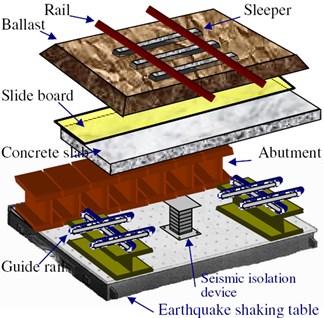
A large-scale shaking table used to reproduce the earthquakes was developed to investigate ballasted track illustrated in Fig. 1 [7]. The performance of the tester is ±60 mm variable displacement, 3G maximum acceleration and 50 Hz maximum vibration frequency. The track length of the test sample is 4.5 m. And eight sleepers set on 200 mm thick waste ballast well compacted. Then applied for a fixed time since wave combined with the maximum acceleration and frequency set in the test conditions. At that time, response acceleration and displacement of sleepers and ballast were measured. Before and after the vibration, three sleepers were measured lateral displacement by applying a horizontal load to each of those sleepers in a direction lateral to the track. The minimum applied load at which lateral displacement reached 2 mm was considered the lateral ballast resistance force.
Fig. 1Test model (after Kumakura T., 2010)
2.2. DEM model
As a method of continuum mechanics, the FEM cannot well represent the large deformation of discontinuities of granular material, which is an important factor to response seismic vibration. In recent years, the DEM (Distinct Element Method) attracts more and more attention, due to its capability in simulating large deformations like sliding and separation of discontinuities [8-9] as well as the non-linear dynamic calculation [10]. DEM is one of the most popular discrete approaches which describe material behaviors directly from particle motions and inter-particle forces transition; it becomes a powerful tool to study the behavior of granular materials by taking into account the interactions among constituents and providing deeper understanding of the granular system at microscopic level. The discrete element method can be computationally intensive, which limits either the length of a simulation or the number of particles. The dynamic behavior is represented numerically by a time stepping algorithm in which it is assumed that the velocities and accelerations are constant within each time step. The method is the same as a finite-difference algorithm. The method has been used successfully to model ballast material characteristic both for monotonic and cyclic loadings [11-12]. The DEM simulations of vibration across normally-distributed granular have been carried out by Cai [13] and Zhao [14], and those simulation results, including the reflection and transmission coefficients and the influence of particle stiffness on wave propagation, agreed well with the theoretical values proposed by Pyrak-Nolte [15] and Schoenberg [16], verifying validity and accuracy of DEM in seismic simulations. Wave propagation through an assembly of discrete bodies is, in general, dispersive [17], and the related vibration and propagation could be analyzed and investigated by DEM [18-23], so the DEM model is developed as following.
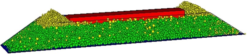
A section of sleeper-ballast track was built to conduct the lateral ballast resistance test to compare with the test on tracks, as Fig. 2 illustrated. The dimensions of the sleeper-ballast were 4500 mm long, 1000 mm wide and 300 mm deep. The walls were constructed according to the geometry of the high speed ballast bed, where shoulder ballast was included. The sleeper were made of walls, to act as the interaction with ballast, such as base wall, side walls and end wall, where the sum of the lateral direction equal to the lateral ballast resistance. The radius multiply method was used to generate the ballast-track model. Smaller clumps were generated within the model and then expanded to a final diameter according to the ballast specifications. The ballast assembly was well compacted by exerting on external forces to the sleeper surface, precisely sank to the ballast with sleeper base to the bottom wall distance was 30 cm. The ballast assembly was cycled to equilibrium using the SOLVE command, which limits the ratio of mean unbalanced force to mean contact force, or the ratio of maximum unbalanced force to maximum contact force to a default value of 0.01 [17]. The sleeper is laterally moved with constant value within quasi-static range, the lateral resistance values were recorded separately. In total, the ballast bed model set up was made up of 4 steps, randomly assembly, radius multiply, compaction and shear displacement.
Fig. 2Ballast-sleeper track DEM model
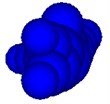
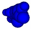
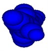
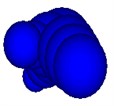
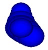
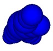
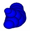
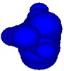
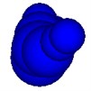
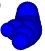
As ballast particle shape is of importance for ballast tests and DEM simulations, it is need to present a more quantitatively reliable model still remained as most of the natural shapes of ballast particles are irregular and angular. The concept of an agglomerate where spheres are bonded together to create complex shapes and simultaneously keep the contact detection and force calculation easy emerged. This paper reproduced a procedure used to model ballast particle shape using many overlapping balls of different sizes to form complex clumps resembling real ballast particles [5]. A clump in the model is made of 19.4 balls in average to simulate the interlock. The Fig. 3 presents several typical ballast particles formed by clump of balls.
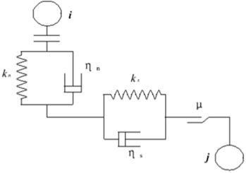
It is a fact that we use the elastic spring and plastic dumper to present the connection of basic element balls in PFC3D. The spring represents the elastic of the ball, while the dumper represents the plastic of the ball. At the same time, we apply a sliding block with friction to show the friction between balls. The mechanic relationship between balls is shown in Figure 4. We assume that there exists a spring with normal elastic coefficient and tangential elastic coefficient , a dumper with normal dump coefficient and tangential dump coefficient and a sliding block with friction coefficient .
Fig. 3Typical irregular clumps
a)
b)
c)
d)

e)
f)
g)
h)

i)
j)
k)
l)
Fig. 4Mechanic connection between balls in PFC3D
In the paper, the clump is made up of many balls. It is important to point out that the clump is regarded a rigid body, meaning that there is no force between the balls consisting of a clump. However, the connection of clumps is through balls, and the balls which are not included in the same clump exist force when they contact. The advantage of applying such kind of clump to model ballast is that clump can present the character of multi-contact between real ballasts. If we use the basic element ball in PFC3D to model ballast, it is obviously that ball has fewer contact points than clump. So it can not represent the complex connection between ballasts.
Mohr-Coulomb contact law was used in the simulations, and based on the ballast DEM simulations [4], the contact parameters are listed on Table 1. For damping, when a dynamic simulation of compact assemblies is required, the local damping coefficient should be set to a low value appropriate to energy dissipation of dynamic waves [17]. It should be noted, for the earthquake vibration response, it is a dynamic simulation, while for the later part, lateral ballast resistance, which is a slowly sleeper pull-out test belongs to equilibrium and to conduct quasi-static deformation simulations, and default value is 0.7.
Table 1DEM parameters
Ballast | Wall | |
Normal / shear stiffness | 5e8 N/m | 1e9 N/m |
5e8 N/m | 1e9 N/m | |
Particle density | 2600 kg/m3 | |
Contact friction | 0.5 | |
Damping | 0.157 / 0.7 | |
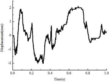
A function generator was used to deliver a sinusoidal signal of adjustable frequency and amplitude to a power amplifier, and then transmitted as the input signal to the ballast bed. Then the dynamic response of the ballast bed lateral resistance tests were carried out, resistance values contrast with sleeper displacements were recorded. A function was programmed to simulate the train cyclic loading using the following sinusoidal expression:
where is the half-amplitude, is the frequency.
After the seismic vibration, the lateral ballast resistance DEM tests were carried out. We measured lateral displacement by applying a horizontal load to each of those sleepers in a direction lateral to the track. The minimum applied load at which lateral displacement reached 2 mm was considered the lateral ballast resistance force. As discussed above, the simulations within quasi-static zone.
3. Results and discussion
In the following, a fixed sine wave combined with maximum acceleration and frequency set in test conditions were applied. The lateral ballast resistance properties in association with vibration frequency and amplitude, duration, ballast particle friction were presented. The data represented dynamic condition computation, the system is not allowed to relax to a static state. In a physical experiment, this would be leading to taking instantaneous measurements (if possible) when the particles is being vibrated rather than when the shaking device is switched off.
3.1. Earthquake effects
Fig. 5 illustrated the shape of the load- deflection curve obtained from the lateral ballast resistance tests, under seismic vibration frequency 5 Hz, 0.5 g amplitude, and duration time is 1 s, with contact friction of particles is 0.5. It can be seen from this figure that the DEM results agreed well with the experiments, and the DEM model presents the typical ballast lateral resistance characteristics. It should be noted that the DEM curve shows the fluctuate movements, indicating the ballast particle slip and slide. It clearly noted that the resistance force hugely reduced after earthquake, the former granular material well contact with sleeper bottom was altered, indicated that granular particles slip and relative displacements were observed between sleeper and ballast particles during earthquake.
Fig. 5Lateral ballast resistance (before and after earthquake)
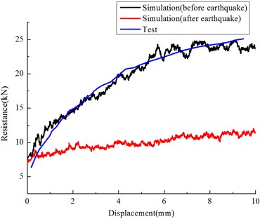
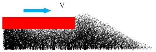
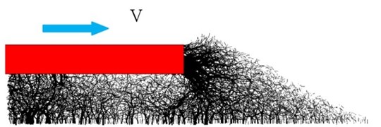
Fig. 6 illustrates the transportation of lateral seismic wave in ballast bed under earthquake. The position of ballasts changed and relocated under lateral seismic load, which results in loose contact between ballast and variation of the force chain. The contact force chain variation was illustrated by Fig. 7 and Table 2. Results show that the force chain variation was altered after earthquake, the maximum and average contact force was reduced, indicated that the well compacted ballast bed become loose. Shoulder ballast contact force chain was changed as shown by the lateral resistance tests, as shoulder ballast is vital for track stability; the force chain alteration is of importance after seismic response.
Fig. 6Transportation of lateral seismic wave in ballast bed under earthquake
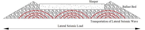
Fig. 7Contact force chain variation

a) Contact force before earthquake
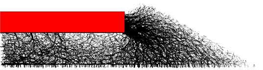
b) Lateral resistance before earthquake
c) Contact force after earthquake
d) Lateral resistance after earthquake
Table 2Contact force during sleeper displacements
Sleeper displacement (mm) | Before earthquake (N) | After earthquake (N) | ||
maximum | average | maximum | average | |
1 | 654.4 | 13.5 | 429.8 | 10.1 |
2 | 696.1 | 14.1 | 441.8 | 10.3 |
3 | 715.1 | 14.5 | 460.5 | 10.4 |
4 | 785.3 | 14.7 | 475.6 | 10.4 |
5 | 870.4 | 14.8 | 512.6 | 10.5 |
6 | 815.6 | 15.1 | 535.3 | 10.5 |
7 | 811 | 15.5 | 575.3 | 10.7 |
8 | 992.9 | 15.7 | 603.9 | 10.9 |
9 | 955 | 15.8 | 673.6 | 11.2 |
10 | 1010 | 16.1 | 785.3 | 11.4 |
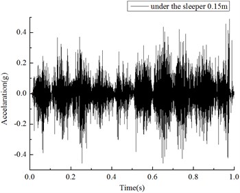
At the same time, response acceleration and displacement ballast were measured. The ballast acceleration located under sleeper middle 15 cm was illustrated in Fig. 8. Results showed that the wave shape of the response acceleration was similar to that of input acceleration.
Fig. 8Acceleration under sleeper 0.15 m (5 Hz, 0.5 g, 1 s input)
The particle displacements under the sleeper during the seismic vibration were recorded as Fig. 9(a). The two neighboring ballast particles relative displacements for -direction as Fig. 9(b). The coordinates are as following, with , , 0.1 0.24 0.34 and 0.1 0.26 0.34.
Fig. 9Particle displacements under the sleeper
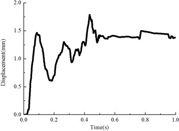
a) Particle displacement under the sleeper
b) Relative displacement of two particles
3.2. Vibration frequency
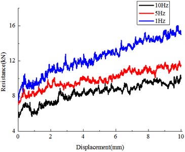
The assessment of the frequency response is a key issue of the present analytical work to establish the ballast bed seismic effects for current seismic design rules. Results presented by Fig. 10 and Table 3 indicated that the lateral resistance reduced with earthquake acceleration increase, higher frequency with the same time duration produce more ballast particles re-displacements, thus more disruption for the compacted initial ballast bed. Results signified that higher frequency results in more reduction for lateral resistance [24]. For example, after 10 Hz, 1 s earthquake duration, more than 50 % reduction of lateral resistance force was observed, the existed value is very dangerous for track stability. It should be noted that, within the low frequency zone, the vibration frequency effects become more dominant.
Table 3Variation with frequency
Frequency | Lateral resistance (kN) | Loss (compared with initial 14.584 kN) |
1 Hz | 10.803 | 25.9 % |
5 Hz | 9.075 | 37.8 % |
10 Hz | 7.066 | 51.5 % |
Fig. 10Influence of vibration frequency
3.3. Vibration acceleration
The sensitivity of vibration acceleration was studied using DEM – see Fig. 11 and Table 4. The Fig. 11 illustrated the resistance force reduced with vibration acceleration, under the condition of disturbance of dynamic force, the granular becomes loose, and the shear strength will decrease remarkably [25-27]. Compared with the amplitude of frequency, the influence of high acceleration on the dynamic shear strength is also significant. This is the results of low frequency, a little contrast for higher frequency vibration.
3.4. Vibration duration
We studied a system of particles with vibration frequency 5 Hz, and magnitude 0.5 g, and friction coefficients 0.5 while the duration time 1 s, 5 s, 10 s respectively. The results were shown in Fig. 12 and Table 5. Results indicated that the lateral resistance reduced with earthquake duration increase, more time duration with the same frequency and amplitude involved higher energy input, thus more disruption for the compacted initial ballast bed. Results signified that time duration are a dominant factor for the lateral resistance, for example, after 5 s earthquake duration, near 60 % reduction of lateral resistance force was observed, which is critical for track stability.
Fig. 11Influence of vibration amplitude
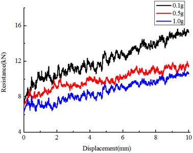
Table 4Variation with amplitude
Earthquake amplitude | Lateral resistance (kN) | Loss (compared with initial 14.584 kN) |
0.1 g | 10.118 | 30.6 % |
0.5 g | 9.075 | 37.8 % |
1.0 g | 6.790 | 53.4 % |
Fig. 12Influence of vibration duration
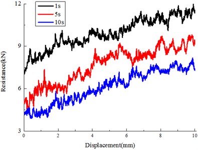
Table 5Variation with time
Duration | Lateral resistance (kN) | Loss (before earthquake 14.584 kN) |
1 s | 9.075 | 37.8 % |
5 s | 6.208 | 57.4 % |
10 s | 4.653 | 68.1 % |
3.5. Contact coefficient
The ballast particle friction is an important factor for lateral resistance of sleeper, as well as the influences the behavior of the vibration. Evidence of this was seen in the results summarized in Fig. 13 and Table 6, which depicted the variation of lateral resistance versus friction coefficient, before and after the earthquake vibration. In order to assess the situation after the system is vibrated, the friction coefficient is varied (0.4, 0.5, 0.6), for amplitudes 0.5 g and duration 1 s, and frequency 5 Hz. Results indicated that for all kinds of ballast particle surface state, after the vibration, over 30 % loss in lateral resistance. The angle of the internal friction (contact coefficient) is the angle of static internal friction when contact plane between the granular does not slip under the action of dynamic, but when the vibration is exerted on the granular assembly, the angle of internal friction will change [9], thus more particle re-displacements were observed during the vibration, hence later loss in lateral resistance. Further, for the smoother or less contact friction ballast particles, the lateral resistance reduction result in track stability problem, due to the existed value is below the safety critical standards [28-30].
Fig. 13Influence of vibration amplitude
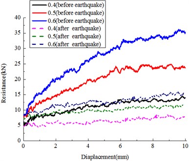
Table 6Variation with contact friction
Contact friction | Before earthquake (kN) | After earthquake (kN) | Loss |
0.4 | 9.375 | 6.286 | 32.9 % |
0.5 | 14.584 | 9.075 | 37.8 % |
0.6 | 20.122 | 11.831 | 41.2 % |
4. Conclusion
DEM has been used to examine the characteristics of railway ballast behavior under vertically vibrated beds. The investigated lateral resistance features varied with frequency, amplitude, and duration and contact friction. Vibration amplitude were found to have significant influence on the lateral resistance, in low frequency zone, lateral ballast resistance was observed to decrease with increasing frequency index, vibration duration. For the smoother or less contact friction ballast particles, the lateral resistance reduction result in track stability problem, due to the existed value is below the safety critical standards, it is necessary to conduct tests or stabilization work on ballast bed after seismic vibration before the operation of train.
In future, characterizing the dynamic behavior of ballast is one of the great challenges in the mechanics of track engineering. Methods for evaluating the mechanical properties of ballast granular have applications in track design and maintenance, with aim to consider the track properties, a coupled Discrete Element Method-Finite Element Method (DEM-FEM) code could be developed and implemented for analyzing the behavior of ballast granular layer under track, an elastic beam under deforming (quasi-static) or vibrating (train dynamic) of the track beam.
References
-
Housner G. W., Lili X. Report on the great Tangshan earthquake of 1967, Chapter 1. Railway engineering, Earthquake Engineering Research Laboratory, California Institute of Technology, Pasadena, CA, Vol. 3, 2002, p. 1-60.
-
Etsuo Sekine, Tatsuya Ishikawa Deformation characteristics of ballasted track during earthquake. RTRI Report, 2005.
-
Esmaeili Mortezam, Hamidreza Heydari Noghabi Investigating seismic behavior of ballasted railway track in earthquake excitation using finite-element model in three-dimensional space. Journal of transportation engineering, Vol. 139, Issue 7, 2013, p. 697-708.
-
Cundall P. A., Strack O. D. L. A Discrete numerical model for granular assemblies. Geotechnique, Vol. 29, Issue 1, 1979, p. 47-65.
-
Lim W. L., McDowell G. R. Discrete element modeling of railway ballast. Granular Matter, Vol. 7, Issue 1, 2005, p. 19-29.
-
Lu M., McDowell G. R. The importance of modelling ballast particle shape in the discrete element method. Granular Matter, Vol. 9, Issue 1-2, 2007, p. 69-80.
-
Kumakura T., Ishii H., Konishi T. Seismic assessment of ballasted tracks in large-scale earthquakes. JR EAST Tech. Rev. Japan, Vol. 17, 2010, p. 25-28.
-
El Shamy U., Zamani N. Discrete element method simulations of the seismic response of shallow foundations including soil-foundation-structure interaction. International Journal for Numerical and Analytical Methods in Geomechanics, Vol. 36, Issue 10, 2012, p. 1303-1329.
-
Ishikawa T., Sekine E., Ohnishi Y. Shaking table tests of coarse granular materials with discontinuous analysis. Proc. of ICADD-5, BALKEMA, p. 181-187.
-
Selig E. T. Trackgeotechnology and Substructure Management. 1994
-
Nagase K., Kondo K., Nomura T. Train damaged by the quake in Kobe EJ. The Japan Society of Mechanical Engineers, Vol. 63, Issue 6, 1997, p. 620-627.
-
Nishimura K., Terumichi Y., Morimura T. Development of vehicle dynamics simulation for safety analyses of rail vehicles on excited tracks. Journal of Computational and Nonlinear Dynamics, Vol. 48, Issue 3, 2009, p. 129-135.
-
Guoping Cai, Jinzhi Huang, Feng Sun Chao Wang Modified sliding-mode bang-bang control for seismically excited linear structures. Earthquake Engineering & Structural Dynamics, Vol. 29, Issue 11, 2000, p. 1647-1657.
-
X. Zhao, Y. Y. Lee, K. M. Liew Free vibration analysis of functionally graded plates using the element-free kp-Ritz method. Journal of Sound and Vibration, Vol. 319, Issue 3-5, 2009, p. 918-939.
-
Laura J. Pyrak-Nolte, Larry R. Myer, Neville G. W. Cook Transmission of seismic waves across single natural fractures. Journal of Geophysical Research: Solid Earth, Vol. 95, Issue B6, 1990, p. 8617-8638.
-
Michael Schoenberg Elastic wave behavior across linear slip interfaces. J. Acoust. Soc. Am., Vol. 68, No. 1516, 1980.
-
Itasca Consulting Group, Inc. PFC3D (Particle Flow Code in Three Dimensions). Version 4.00, Minneapolis.
-
Miyamoto T., Ishida H., Matsuo M. Running safety of railway vehicle as earthquake occurs. QR of RTRI, Vol. 38, Issue 3, 1997, p. 117-122.
-
Nishimura K., Terumichi Y., Morimura T., et al. Experimental study on the vehicle safety by earthquake track excitation with I/IO scale vehicle and roller rig. Journal of System Design and Dynamics, Vol. 4, Issue 1, 2010, p. 226-237.
-
Grassie S. L., Gregory R. W., Johnson K. L. The dynamic response of railway track to high frequency lateral excitation. J. Mech. Eng. Sci., Vol. 24, Issue 2, 1982, p. 91-95.
-
Kish A., Samadevam G, Wormley D. Fundamentals of Track Lateral Shift for High-Speed Rail Applications. European Rail Research Institute, 1998.
-
É. Azéma Étudenumérique des matériauxgranulaires à grains polyédriques: rhéologie quasi-statique, dynamiquevibratoire, application au procédé de bourrage du ballast. PhD thesis, Université Montpellier 2, 2007.
-
Ricci L., Nguyen V. H., Sab K., Duhamel D., Schmitt L. Dynamic behaviour of ballasted railway tracks: a discrete/continuous approach. Comput. Struct., Vol. 83, 2005, p. 2282-2292.
-
Aixiang Wu, Yezhi Sun Granular Dynamic Theory and its Applications. Metallurgical Industry Press, Beijing, 2008.
-
Zhai W. M., Wang K. Y., Lin J. H. Modelling and experiment of railway ballast vibrations. Journal of Sound and Vibration, Vol. 270, 2004, p. 673-683.
-
Hiroki Hirao, Esmaeili Morteza Vibration tests of a ballasted track model using a shaking table tester, Part 2: Ballast resistance force. Paper submitted for the 63th annual lecture meeting of the Japan Society of Civil Engineers, 2008.
-
Etsuo Sekine, Tatsuya Ishikawa Evaluating seismic resistant performance of ballasted track by cumulative damage model. RTRI Report, 2006.
-
Hiroshi Mori, Yoshimi Ogawa, Guoqiang Cao Liquefaction analysis of river dike with discrete element method. Tsuchi to Kiso, Vol. 52, Issue 11, 2004, p. 44-46.
-
N. Zamani, U. El Shamy DEM simulations of wave propagation in dry granular soils. Acta Geotechnica, Vol. 6, Issue 3, 2011, p. 167-182.
-
U. EI Shamy, N. Zamani DEM simulations of the seismic response of soil-foundation-structure systems. GeoCongress, 2012, p. 1730-1739.
About this article
Research reported in this paper was supported by Natural Science Foundation of China (51108026, U1234211), and the Beijing Natural Science Foundation (No. 8132037).
