Abstract
The aim of this paper is to describe two modifications of high resolution rotary tables with angular position control, based on the transformation of resonant oscillations of piezoelectric transducers into continuous or start-stop motion. Exact angular position of the table is achieved by application of integrated classical rotary position encoders and feedback system, related to the given position or angular velocity of the device. Dimensions and cost of the table should be dramatically reduced, thus ensuring competitiveness in modern markets.
1. Introduction
There is a great deal of researchers who are developing various piezoelectric devices, including rotary tables and motors [8]. However, only several companies managed to produce and supply such objects to the market. German company PI (Physik Instrumente GmbH & Co, Germany) developed piezotable M 660, characterized by angular resolution up to 4 µrad and maximal angular velocity, equal to 2 rev/min [9]. Technical parameters of this product are excellent, but price reaches 1000 EUR and that limits the cases of its practical use. Nanomotion Ltd (Israel) commercialised its FBR060 model, which utilises the same way of motion generation, as that of previously described device [10] and the cost is nearly the same, although the main technical features are different. Another operation principles based on transformation of non-harmonic oscillations (stick-slip effect) are embodied by companies Attocube Systems AG (Germany) and PiezoMotor AB (Sweden) in the models ANR101/NUM Closed Loop [11] and Piezo LEGS WavePlate [12]. The prices of both piezoelectric tables are even higher compared to the ones discussed before. In addition, piezomotors designed by company PCB Motor ApS (Denmark) should be mentioned. These motors are manufactured on printed boards and have no outer covers (for example, PCBM 30-H25 [13]). Nonetheless, the latter positioning stages are of different precision class.
Information provided in this article mainly deals with the development of two versions of the novel table, based on the combination of standard photoelectric rotary encoders (A36-F-4000-5V and A58-F-10240-5V), produced by Precizika Metrology (Lithuania), and plate-type piezoelectric actuators, invented in Kaunas University of Technology (Lithuania). Both modifications act as prototypes for the industrial products that would be characterized by high quality and relatively low cost.
2. Optimal topology of electrodes
When designing a plate-type piezoelectric drive used in this work, a great attention was paid to optimal topology of electrodes on piezoceramic element. This issue was taken into consideration when performing R&D project PiezoAdapt [14]. During problem formulation for multi-dimensional piezoelectric transducers in terms of optimal electrodes configuration, the following constrains are taken into account: unification of excitation voltage, generation of reversal motion and achievement of maximum efficiency. The first requirement deals with voltage of the same frequency, constant amplitude and phase, supplied by power source. The second one is met by changing only polarity of the power source, while the third one is met when the surface of piezoelement is covered by electrodes completely and all their zones are simultaneously excited using appropriate polarity voltage. This voltage, referring to the second constraint, differs just by a phase, depending on the mode of oscillations desired to be excited. After detailed research it was found that in order to obtain maximum efficiency, the functioning of piezoelectric plate should satisfy the following expression [14]:
where is effcient work; is value of vector of piezoelement’s natural form; is value of vector of equivalent mechanical force; is angle between both vectors; is constant.
For numerical determination of optimal electrodes, the topology to be applied to the electrodes of piezotransducer has to be sectionned by means of finite elements (FE) so excitation voltage’s polarity in the centre of unitary finite element is treated as optimised parameter. The sign of polarity can be found comparing directions of equivalent mechanical force vector and that of piezoelement’s natural form. Based on that, the essential criterion of the overall problem is the angle between two given vectors, which has to be minimized. The coefficient of efficiency is [14]:
After calculating for each surface element of piezotransducer, the optimal topology of electrodes is defined. Sign of cosine function means the sign of excitation voltage polarity. If cosine is positive, equivalent mechanical force acts in necessary direction, otherwise (i.e. cosine is negative) there is a need to change voltage polarity. The greater value of cosine is, the more influence corresponding finite element has on trying to induce certain mode of vibrations in piezoelectric element [14].
If optimisation calculations are associated with defined natural frequency, the value of vector of piezoelement’s natural form is constant as well. In such case efficient work only depends on the value of coefficient of efficiency, so optimal configuration of electrodes is determined by minimising described angle. Angle can be changed, if only direction of equivalent mechanical force vector is changed. Such procedure is implemented when excitation voltage polarity is modified [14].
Optimal topology of two-dimensional piezoceramic element electrodes was computed and stated as an example, according to the formulated algorithm, with finite element method and ANSYS software to be applied. Analyzed piezoplate was constrained in its central nodes, since piezoelectric drives of this type are often applied for generating rotational motion. Result of such calculation (i.e. coefficients of efficient action), attributed to the centre of each finite element mass, is given in Fig. 1(a). Bright thick line stands for separated electrode zones having the same excitation voltage with phase shifted by . Fig. 1(b) reveals topology of electrodes so as to induce longitudinal-bending mode oscillations in 2D piezoceramic element. It was created referring to personal engineering perception and intuition. Obviously, configurations are very similar in both cases [14, 15].
Fig. 1a) FEM-based optimisation of electrodes topology: cosine values (coefficients of efficiency) (×0.1) for two-dimensional piezoceramic element constrained in its central nodes, b) topology of electrodes created referring to personal engineering perception and intuition [4, 5]
![a) FEM-based optimisation of electrodes topology: cosine values (coefficients of efficiency) (×0.1) for two-dimensional piezoceramic element constrained in its central nodes, b) topology of electrodes created referring to personal engineering perception and intuition [4, 5]](https://static-01.extrica.com/articles/14790/14790-img1.jpg)
a)
![a) FEM-based optimisation of electrodes topology: cosine values (coefficients of efficiency) (×0.1) for two-dimensional piezoceramic element constrained in its central nodes, b) topology of electrodes created referring to personal engineering perception and intuition [4, 5]](https://static-01.extrica.com/articles/14790/14790-img2.jpg)
b)
3. Rotory table modifications
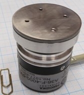
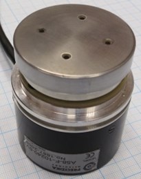
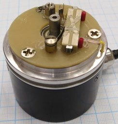
With the aim to define technical properties of potential industrial piezoelectric high resolution table, two initial relevant modifications were constructed incorporating standard photoelectric rotary encoders (A36-F-4000-5V and A58-F-10240-5V) and plate-type piezoelectric drives, as it was presented in the introduction of this text. Both table versions employ multilayer piezoceramic elements with sectioned electrodes, made by Noliac Group (Denmark), with dimensions being 20 mm×4.5 mm×2 mm (for encoder A36) and 30 mm×7.5 mm×3 mm (for encoder A58). Number of layers was 40 for both plates. Positions of the tables were registered using two and three axis readout devices CS 3000. Integration of mentioned encoders and piezodrives, which contact with internal cylindrical surface of rotating part of the table, is shown below (see Fig. 2, 3).
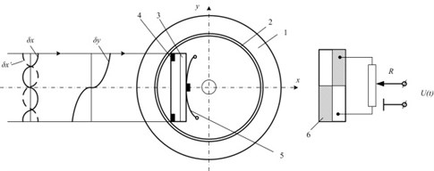
Fig. 2First modification of piezoelectric high resolution rotary table: a) photoelectric angular position encoder A36-F-4000-5V, b) rotating part, c) optimisation scheme for contact element trajectories : 1 – rotating part, 2 – precise ring, 3 – piezoelectric multilayer plate, 4 – contacting elements, 5 – spring, 6 – sectioned electrodes; resonant frequency – 75.2 kHz, harmonic excitation amplitude – 10 V
a)
b)
c)
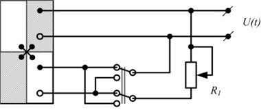
Generally dynamic characteristics of the table are significantly influenced by motion trajectories of contacting elements. Taking into account this fact, a few technical solutions were proposed (Fig. 2(c) and Fig. 4(a)-(b)) to optimise the trajectories depending on the maximal angular speed of the device. Longitudinal first mode and bending second mode (in the plane of piezoplate) vibrations are induced within piezoelectric transducer in both table modifications; that leads to elliptical trajectories (with mutual phase difference of 180°) of either contacting points. The shape of ellipse is defined by both resonant frequency difference, which is also governed by geometry of piezoelectric transducer, and operation regime, which usually attains frequency value in between resonant frequencies, attributed to each oscillation mode.
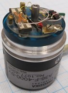
Fig. 3Second modification of piezoelectric high resolution rotary table: a) photoelectric angular position encoder A58-F-10240-5V, b) without rotating part, c) angular position registration device CS 3000; resonant frequency – 42.1 kHz, harmonic excitation amplitude – 10 V
a)
b)
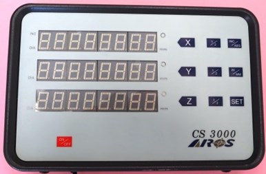
c)
The scheme provided in Fig. 2(c) enables to control motion trajectory of discussed contacting elements by means of potentiometer in the range from longitudinal vibrations of piezoplate with respect to axis (middle position of potentiometer) to elliptical ones (top or bottom position of potentiometer) in plane. Even further limits for regulation of trajectory are set, if one applies the scheme shown in Fig. 4a (i.e. from longitudinal vibrations with respect to axis to transversal oscillations with respect to axis). The same effect is obtained when using signal transformer with symmetrical output (Fig. 4b).
Fig. 4Schemes for optimisation of motion trajectory of contacting elements
a)
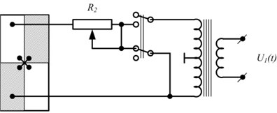
b)
4. Experimental results
The schemes revealed in Fig. 2(c) and Fig. 4(a), (b) were utilised in experiments during investigation of two versions of the novel piezoelectric rotary table. Trajectories of 2D vibrations of reference point of piezoelectric rotary table output link were formed using laboratory experimental setup. Its structural scheme is disclosed in Fig. 5, while the major results are demonstrated in Fig. 6 and 7. In order to measure reference point (AT) vibrations with respect to X and Y directions, laser vibrometer (LV) Polytec was employed, consisting of laser sensor OFV-130-3, interferometer OFV-512 and vibrometer controller OFV-5000. Oscillations of piezoelectric transducer are generated when harmonic signal is supplied from signal generator Agilent 33220A (G) via signal amplifier EPA-104 (ST). Signals obtained from laser vibrometer are passed to four-channel oscilloscope PicoScope-3424 (OSC) and processed by appropriate software. Synchronised generator signal is required, so that identical duration time signals associated with positions X and Y, would be adopted. In such case vibrometer data is stored in oscilloscope and transferred to computer when starting with the same phase of generator in both X and Y positions. For graphic representation of formed trajectory in the computer, the stored data is extracted pair-by-pair (X and Y) and plotted in XY coordinate-based graph. As a result nearly ellipse-shape figure is got.
Fig. 5Structural scheme of experimental setup for trajectories of 2D vibrations of reference point of piezoelectric rotary table output link to be measured: PZT – piezoelectric transducer, AT – reference point of piezotransducer’s output link, X and Y – measurement directions of reference point vibrations, LV – laser vibrometer, OSC – oscilloscope, PC – computer, G – signal generator, ST – signal amplifier
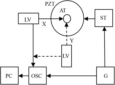
Fig. 6Dynamic properties of piezoelectric rotary table with photoelectric encoder A36: a) amplitude-frequency characteristics of transducer’s contacting point, b) motion trajectory (longitudinal vs transversal) of transducer’s contacting point when voltage (10 V) is supplied to one pair of electric contacts (vibrational frequency – 75.1 kHz)
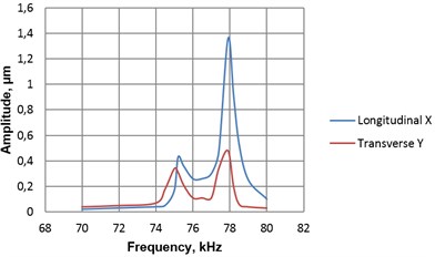
a)
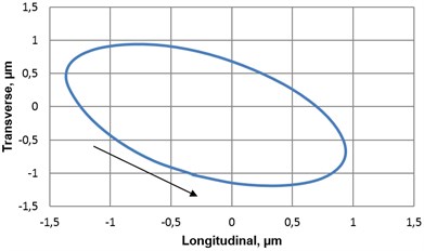
b)
Fig. 7Dynamic properties of piezoelectric rotary table with photoelectric encoder A58: a) amplitude-frequency characteristics of transducer’s contacting point, b) motion trajectory (longitudinal vs transversal) of transducer’s contacting point when voltage (14 V) is supplied to one pair of electric contacts (vibrational frequency – 42.1 kHz)
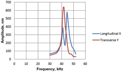
a)
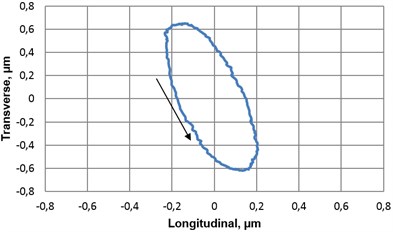
b)
Fig. 8Experimental research of angular resolution of the piezoelectric rotary table: a) minimal angular displacement (0.31’) of piezoelectric rotary table with photoelectric encoder A36 (R= 22 mm) when number of trigger cycles is equal to 50, amplitude – 10 V, b) minimal angular displacement (1.7’) of piezoelectric rotary table with photoelectric encoder A58 (R= 27 mm) when number of trigger cycles is equal to 50, amplitude – 16 V
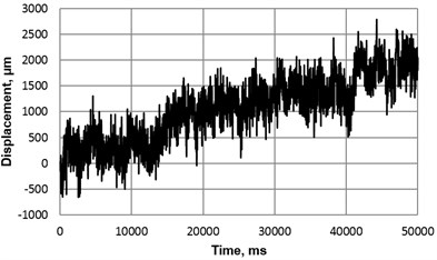
a)
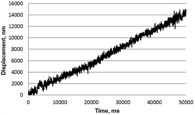
b)
5. Conclusions
Two modifications of piezoelectric high resolution rotary table, that act as prototypes for potential industry-devoted products, were designed, constructed and presented in this work. Successful integration of standard photoelectric rotary encoders (A36-F-4000-5V and A58-F-10240-5V) and plate-type piezoelectric drives result in promising applications.
Optimal topology of electrodes with respect to 2D piezocelectric element was determined by means of finite element method. Three technical solutions (on schematics level) were originally proposed to optimise motion trajectories of contacting elements, which play a crucial role between piezoplate and rotating part of table.
According to the experimental results, the table with photoelectric encoder A36 is able to generate a slightly more uniform rotational motion and achieve higher resolution (minimal displacement – 0.31’), than table with encoder A58 (minimal displacement – 1.7’). However, performance of both table versions can be treated as meeting the initial requirements.
References
-
Li J., et al. A piezoelectric-driven rotary actuator by means of inchworm motion. Sensors and Actuators A: Physical, Vol. 194, 2013, p. 269-276.
-
Buechi R., et al. Inertial drives for micro- and nano-robots: two novel mechanisms. SPIE Proceedings, Vol. 2593, 1995, p. 80-88.
-
Wang C. Y., Chang H. S. Design and performance of a piezoelectric actuated precise rotary positioner. Review of Scientific Instruments, Vol. 77, 2006, p. 1-5.
-
Shim Y. J., Gweon G. D. Piezo-driven metrological multiaxis nanopositioner. Review of Scientific Instruments, Vol. 72, Issue 11, 2001, p. 4183-4187.
-
Zhang H., et al. Impact drive rotary precision actuator with piezolectric bimorphs. Frontiers of Mechanical Engineering in China, Vol. 3, Issue 1, 2008, p. 71-75.
-
Gao W., Sato S., Arai Y. A linear-rotary stage for precision positioning. Precision Engineering, Vol. 34, 2010, p. 301-306.
-
Watson B., Friend J., Yeo L. Piezoelectric ultrasonic micro/milli-scale actuators. Sensors and Actuators A: Physical, Vol. 152, 2009, p. 219-233.
-
Uchino K. Piezoelectric ultrasonic motors: overview. Smart Materials and Structures, Vol. 7, 1998, p. 273-285.
-
Catalogue of Company PI, 2013, http://www.physikinstrumente.com
-
FBR series rotary stage. Nanomotion, http://www.nanomotion.com/index.aspx?id=2572&itemID=1573
-
Attocube – Pioneers of Precision. Product Catalog, 2012 and 2013, Miunich.
-
Piezo LEGS WavePlate. Piezomotor, http://www.piezomotor.se/products/rotary/piezo-legs-waveplate
-
Catalogue of Company PCBMotor. 2013, http://pcbmotor.com/insight/applications-and-solutions
-
Research and development of the multi-degree-of-freedom mechatronic displacement generation/measurement systems with nanometer resolution (acronym PiezoAdapt). Report for High-tech development program, 2011.
-
Cepulkauskas A., Kulvietiene R., Kulvietis G. Computer algebra for the formation structural matrices of piezoceramic finite elements. Lecture notes in computer science, Springer-Verlag, Berlin, Heidelberg, New York, Vol. 3992, 2006, p. 407-413.
About this article
This research is funded by Research Council of Lithuania (Project PiezoTable, No. MIP 094/12).
