Abstract
Lunar exploration is one of the most important projects in the world. A primary objective of the probe in lunar is to soft-land a manned spacecraft on lunar surface. The soft-landing system is the key composition of the lunar lander. In the overall design of lunar lander, the analysis of touchdown dynamics during landing stage is an important work. In this paper, firstly, based on the mechanical theory, a finite element model for the lunar lander is established. Secondly, the linear static structural analysis under particular conditions is performed to determine the nodal stress and displacement distributions and the modal analysis is conducted to obtain the frequencies and their corresponding vibration shapes. Finally, the weakness parts of the structure and the behavior of the system are obtained by analyzing the simulating results, which are beneficial to the optimizing design for the lunar Lander.
1. Introduction
Along with the developments of sciences and technologies, a lot of explorations have been taken in many countries or organizations in succession. Lunar, the natural satellite of the earth, has been a focus of the space discovery again recently because of its abundant resource and high value in use [1]. In particular, the lunar exploration project of China is underway, and a lunar lander will be developed and launched onto the lunar surface in the next step [2].
In order to conduct an effective probe, the lunar lander has to undergo the loads applied by the outer environment to prevent damages of the structure triumphantly. It is well known that structures can resonate, then small forces can result in important deformation, and possibly, damage can be induced in the structure [3-4]. As a result, linear static structural analysis and modal analysis are performed essentially to verify the structure of the lunar lander before being put into use.
Modal analysis is a primary tool that structural engineers use regularly. It has become the backbone of linear structural dynamics and related fields like aero elasticity. The use of modal analysis is expanding rapidly, with one notable example being the widespread application of the method to investigate the structural dynamics characteristics of mechanical systems [5]. The modal pairs, which consist of frequencies and their corresponding vibration mode shapes, are used to predict the dynamic behavior and identify the cause of vibration problems. The important advantage of using natural modal analysis is the tremendous insight gained into the characteristics and behavior of the system. The frequencies and vibration mode shapes of the system can be obtained by performing the modal analysis, and then the weakness part of the structure and the behavior of the system are predicted [6].
On the other hand, Finite Element modeling is a widely used technique to model the dynamic behavior of a large class of systems namely structural element of mechanical devices [7-8]. Recent work at NASA Langley Research Center has examined the development and validation of finite element modeling techniques for aircraft structures to better predict the dynamic response [9].
2. The finite element model of the lunar lander
The structure of the lunar lander used in this paper, which must satisfy the structural, mechanical, and landing-performance constraints, is designed by NUAA. As shown in Fig. 1(a). Four steel outrigger trusses provide the attachment points for the landing-gear struts. Each of the four landing-gear assemblies consists of a primary strut (with a footpad at its lower end) and two secondary struts. The primary strut consists of an inner cylinder, an outer cylinder connected through a universal joint at its upper end to the outrigger truss (Fig. 1(b)), and a crushable aluminum honeycomb cartridge that acts in compression to absorb energy. Each secondary strut consists of an inner cylinder connected through a sleeve-journal universal joint to the outer cylinder of the primary strut, an out cylinder connected through a universal joint to the bottom surface of the module, and honeycomb cartridges which absorb energy while the double-acting secondary strut is lengthening or shortening [10-11].
Fig. 1Sketches of the lunar lander with the 3-D universal joint
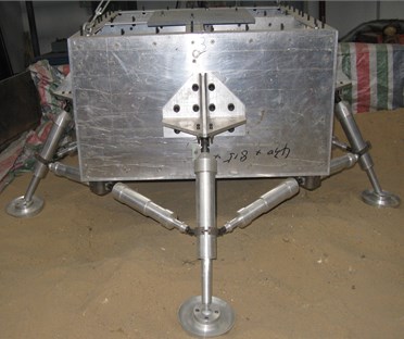
a) Configuration of the lunar lander
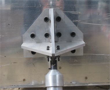
b) Configuration of the 3-D universal joint
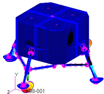
The geometrical accuracy of the CAD model and the discretization of this geometry into a finite element mesh are of paramount importance in obtaining a finite element model which is used to predict the behavior of the mechanical structure [12]. According to the lunar lander's configuration narrated above, a finite element models, including material properties and element properties, is developed in MSC.Patran (Fig. 2(a)). This finite element model consists of elements of bars, beams and shells, such as bar2, beam and quad4 [13-14]. The total number of finite element mesh is up to 93000, while the number of freedom degrees is up to 200000.
Fig. 2Sketches of the finite element model with the simplified joint
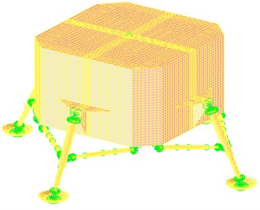
a) Sketch of the finite element model
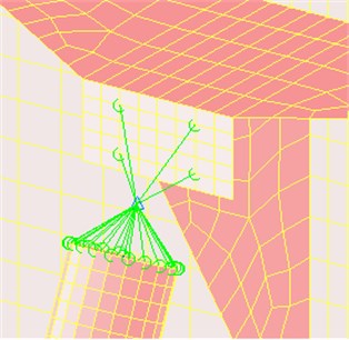
b) Sketch of the simplified joint
As illustrated in Fig. 2(b), the 3-D universal joint is simplified by establishing MPC element, 1-D Bush properties, and 0-D Mass properties [15]. In order to conduct a precise analysis, the finite element model simplified has to represent the original 3-D structure as regards its material and structural properties [16].
3. Structural analyses for lunar lander
3.1. Constraints and loads
The upper surface of the finite element model is constrained in all six degrees of the freedom. The loads corresponding to the case 4 g are applied on the bottom surfaces of the four footpads as uniform pressure accounting for the forces applied by the lunar surface. Linear static structural analysis is submitted to MSC.Nastran to study the response of the landing system in terms of deflection and stress.
3.2. Presentation of the displacement
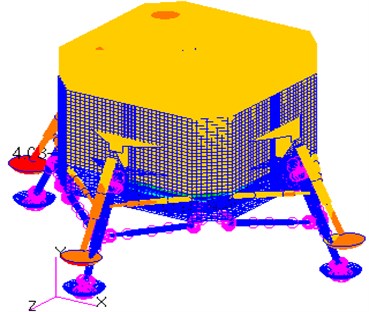
Fig. 3 shows the displacement contour of the results from the linear static structural analysis. It can be inferred from the Fig. 3 that the loads applied on the footpads bend the landing-gear assemblies from the joint point outwards. With the increase in the height, displacements appearing on the finite elements of the main struts are reduced from 0.0614 m to zero. With the increase in the distance to the center of the model, the displacements appearing on the finite elements of the secondary struts are on the increase.
Fig. 3Displacement contour
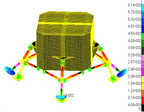
The displacements are maximum at the outermost points of the footpads, and the maximum strain is equal to 0.0614 m. The landing-gear radius () of the model is equal to 2.2 m, then the is 2.8 %, which is a smaller rate. So, the stiffness of the structure is enough. However, the displacements on the inner cylinders of the main struts reduce quickly with the increase of the height, so the inner cylinders of the main struts bend to the out side sharply. So, the inner cylinders of the main struts are the weakness parts of the structure in the term of stiffness.
3.3. Presentation of the displacement
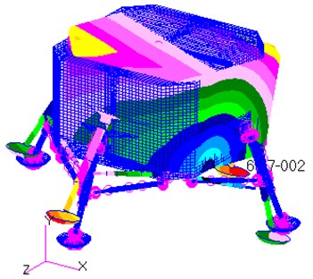
Fig. 4 displays the stress contour of the results from the linear static structural analysis. It can be inferred from the Fig. 4 that the distribution of the stress on the landing-gear struts is not uniform. Several stress-larger areas appear on the outside of the primary struts (Fig. 4(a)), what is attributed to the sharp bend of the primary struts (as the displacement contour shown in Fig. 3). At the same time, the phenomenon of stress concentration occurs on the junction between the primary struts and the secondary struts, as shown in Fig. 4(b).
It is found that the maximum stress generates inner side of the junction between the primary strut and the secondary strut. The maximum stress is equal to 210 Mpa which is less than allowed stress of material 484 Mpa. However, the junction between the primary struts and the secondary struts, and the inner cylinders of the primary struts are also dangerous parts in the term of strength under this operating condition.
Fig. 4Stress contour
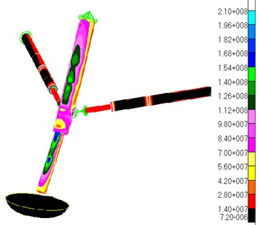
a) Looking from the outside
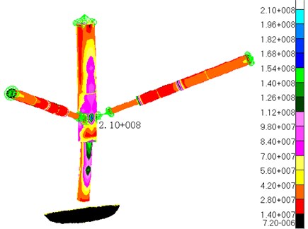
b) Looking from the inside
4. Modal analysis for lunar lander
4.1. The basic theory for the modal analyses
Multiple-degree-of-freedom systems (MDOF) are represented by the following Eq. (9):
where and are respectively mass, damping, and stiffness matrices, the dimensional vector variable indicates a position of a lumped mass on the structure, and the dimensional vector variable describes the externally applied force.
Transforming Eq. (1) to the Laplace domain (assuming zero initial conditions) yields:
With the dynamic stiffness matrix:
The transfer function matrix between displacement and force vectors, , equals the inverse of the dynamic stiffness matrix:
With the numerator polynomial matrix given by:
And the common-denominator polynomial , also known as the characteristic polynomial:
When the damping is small, the roots of the characteristic polynomial are complex conjugate pole pairs, and , , with the number of modes system. The transfer function can be rewritten in a pole-residue form:
The residue matrices , are defined by:
It can be shown that the rank of the matrix is that can be decomposed as:
with a vector representing the “modal shape” of mode . From Eq. (7), it is obvious that the full transfer function matrix is completely characterized by the modal parameters, the poles , and the mode shape vectors , .
4.2. Constraints for the modal analyses
The bottom of the rocket nozzle frame is fixed in all six degrees of freedom, while the other parts of the system are free in all six degrees of freedom. Modal analysis with the clamped boundary conditions is submitted to MSC.Nastran to extract the first six modes, and the natural frequencies and their corresponding vibration mode shapes are obtained.
4.3. Presentation of results
The pre-processing and post-processing of the finite element data are accomplished using MSC/Patran. The natural frequencies and their corresponding mode shapes are recovered, plotted, and animated in three dimensions to provide a visual understanding of the dynamic response.
Only the lower frequencies and vibration mode shapes are of interest because they adequately describe the dynamic behavior of the model [17-19]. Table 1 lists the frequencies and maximum displacements of the first six flexible modes.
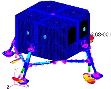
As shown in Table 1, the frequency range in the analysis is from 9 Hz to 36 Hz, while the range of their corresponding maximum displacements is from 0.07 m to 0.5 m. The corresponding vibration mode shapes for the frequencies of the lunar lander are shown in Fig. 5.
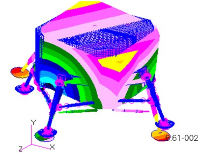
The first mode shape is the rotation of the entire model around the axis (Fig. 5(a)), while the second mode shape is the rotation of the entire model around the axis (Fig. 5(b)). As shown in the Fig. 5(c), the third mode shape is the stretching along the axis direction. It is noteworthy that the bottom of the rocket nozzle is fixed in all six degrees of freedom, so flexible deformation occurs on the bottom surface of the model.
Table 1Frequencies and maximum displacement of the first six flexible modes
Mode | Frequency (Hz) | Maximum displacement (m) |
1 | 9.145 | 0.0661 |
2 | 9.246 | 0.0657 |
3 | 13.193 | 0.0403 |
4 | 34.972 | 0.363 |
5 | 35.310 | 0.371 |
6 | 35.499 | 0.498 |
Fig. 5Sketch of the mode shapes of the first six modes
a) The 1st mode
b) The 2rd mode
c) The 3rd mode
d) The 4th mode
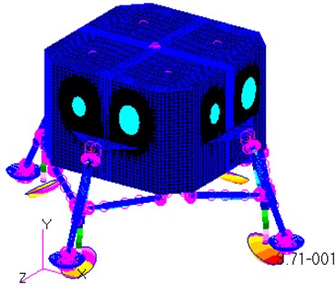
e) The 5th mode
f) The 6th mode
As shown in Fig. 5(d), the vibration shape of the 4th mode is the inward bend of two primary struts around the junction points between the primary struts and the module, while the others bend outwards. All the four primary struts bend inwards for the 5th mode, whereas all of them bend outwards for the 6th mode. To sum up, the vibration shapes for the mode 4, mode 5 and mode 6 are the bends of the primary struts around the junction points between the primary struts and the module.
As shown in Table 1, the value of each frequency is close to the contiguous one. It indicates that the lunar lander is likely to resonate, when the frequency of the external excitation is in the range from 9 Hz to 36 Hz. Then, small external exciting forces can result in important deformation, and possibly, damage can be induced in the structure of the lunar lander.
It is referred from the Fig. 5 that the maximum displacement of each mode shape is at the outside of the footpads. In particular, the maximum displacement for the 6th mode is up to 0.498 m. In other word, the primary struts of the landing-gear assemblies and the bottom surface of the module are the weakness parts of the lunar lander in the term of modal.
5. Conclusions
(1) The nodal stress and displacement distributions under the loads corresponding to 4 g are obtained by performing a linear static structural analysis in MSC.Nastran. The results indicate that the stresses are maximum at the point of junction between the primary strut and the secondary, while the displacements are maximum at the outside of the footpads. The inner cylinders of the primary struts and the junction parts between the primary struts and the secondary struts are the weakness parts of the structure in the term of stiffness because of the sharp bends.
(2) The modal analysis with the clamped boundary condition fixing the bottom of the rocket nozzle in all the six degrees of freedom is conducted to determine the first six modes. The frequencies range is 9 Hz to 36 Hz, while their corresponding maximum displacements are from 0.06 m to 0.5 m. The vibration mode shapes for the first three modes are the flexible deformation of the bottom surface of the module, whereas another one is the bends of the primary struts. So, the bottom surface and the inner cylinders of the primary struts are the weakness parts in the term of the vibration.
(3) The optimizing design for the lunar lander is need to perfect the stiffness and strength of the weakness parts.
References
-
Jinbao Chen, Hong Nie Overloading of landing based on the deformation of the lunar lander. Chinese Journal of Aeronautics, Vol. 21, Issue 1, 2008, p. 43-47.
-
Fan Shichao, Feng Yaoqi The experimental facility for lunar rover development. Spacecraft Environment Engineering, Vol. 24, Issue 2, 2007, p. 85-87.
-
Chen Jinbao, Nie Hong, Zhao Jincai Review of the development of soft landing buffer for Lunar Explorations. Journal of Astronautics, Vol. 29, Issue 3, 2008, p. 731-735, (in Chinese).
-
Jinbao Chen, Hong Nie, Wei Bo Research on touchdown performance of soft landing system with flexible body. Journal of Vibroengineering, Vol. 15, Issue 3, 2013. p. 1255-1260.
-
Mayuresh J. P. Decoupled second-order equations and modal analysis of a general neoconservative system. AIAA-2000-1654, 2000.
-
Yang Xuexia, Liu Na Modal analysis for the structure frame of three-floated gyro based on ANSYS. Modern Manufacturing Engineering, Vol. 7, 2009, p. 131-134, (in Chinese).
-
Morais P. G., Silva J. M., Carvalhal F. J. A specialized element for finite element modal updating of moveable joints. Multibody system dynamics. 5th ed., Kluwer Academic Publishers, Netherlands, 2001.
-
Caijun Xue, Xiuli Xue, Wengang Qi Research on the performance of buffer for landing gear based on the drop test. Journal of Vibroengineering, Vol. 14, Issue 2, 2012, p. 794-804.
-
Ferdinand W. G. Structural normal mode analysis of the aluminium tested cylinder. AIAA-98-1949, 1998.
-
Mayuresh J. P. Decoupled second-order equations and modal analysis of a general nonconservative system. AIAA-2000-1654, 2000.
-
Ulesse J. B. Full-scale dynamic landing-impact investigation of a prototype Lunar module landing gear. NASA TN D-5029, 1969.
-
Shuangli Long, Hong Nie, Caijun Xue, Xin Xu Aeroacoustic testing of the landing gear components. Journal of Vibroengineering, Vol. 14, Issue 1, 2012, p. 205-215.
-
William F. R. Apollo Experience Report-Lunar Module Landing Gear Subsystem. NASA TN D-6850, 1972.
-
Hocknell A., Mitchell S. R., Jones R. Hollow golf flub head modal characteristics: determination and impact applications. Experimental Mechanics, Vol. 32, Issue 2, 1998, p. 140-146.
-
MSC.NASTRAN, MSC.PATRAN documents.
-
Wang Chunjie, Guo Yong Dynamic analysis of lunar lander. Journal of Beijing University of Aeronautics and Astronautics, Vol. 35, Issue 2, 2009, p. 183-187, (in Chinese).
-
Sivaji R., Marisarla S., Narayanan V., et al. Aerodynamic and structural analysis of joined wings of hale aircraft. New developments in computational fluid dynamics, Heidelberg, Springer, Berlin, 2005, p. 152-164.
-
Ooi T. K., Gilbert J. A., Bower M. V. Modal analysis of lightweight graphite reinforced silica/polymer matrix composite plates. Experimental Mechanics, Vol. 45, Issue 3, 2005, p. 221-225.
-
Caijun Xue, Guang Zheng, Long Wei, Shuangli Long Aeroacoustic noise reduction design of a landing gear structure based on wind tunnel experiment and simulation. Journal of Vibroengineering, Vol. 14, Issue 4, 2012, p. 1591-1600.
About this article
The authors are grateful to prof. Hong Nie for discussions and Zemei Zhang for providing helps. The authors would also like to thank the anonymous reviewers for their critical and constructive review of the manuscript. This study was co-supported by the National Natural Science Foundation (No. 51105196) and National Natural Science Foundation of Jiangsu (No. BK2011733).
